Connecting Device
Chen; Ken-Ching ; et al.
U.S. patent application number 16/503595 was filed with the patent office on 2020-09-17 for connecting device. The applicant listed for this patent is KING SLIDE TECHNOLOGY CO.,LTD., KING SLIDE WORKS CO., LTD.. Invention is credited to Ken-Ching Chen, Ci-Bin Huang, Fang-Cheng Su, Yue-Hua Tang, Chun-Chiang Wang.
| Application Number | 20200291976 16/503595 |
| Document ID | / |
| Family ID | 1000005059779 |
| Filed Date | 2020-09-17 |


View All Diagrams
| United States Patent Application | 20200291976 |
| Kind Code | A1 |
| Chen; Ken-Ching ; et al. | September 17, 2020 |
CONNECTING DEVICE
Abstract
A connecting device adapted to connect a first wall and a second wall of a furniture piece is disclosed. The connecting device includes a base portion and at least one engaging arm. The base portion is connected to the first wall of the furniture piece. The at least one engaging arm is arranged at the base portion. The at least one engaging arm is resiliently movable around a hypothetical axis. The at least one engaging arm is arranged with an engaging portion. The hypothetical axis is substantially parallel to the first wall. The second wall of the furniture piece is mountable to the engaging portion along a mounting direction via a mounting portion. The mounting direction is substantially perpendicular to the hypothetical axis.
| Inventors: | Chen; Ken-Ching; (Kaohsiung City, TW) ; Su; Fang-Cheng; (Kaohsiung City, TW) ; Huang; Ci-Bin; (Kaohsiung City, TW) ; Tang; Yue-Hua; (Kaohsiung City, TW) ; Wang; Chun-Chiang; (Kaohsiung City, TW) | ||||||||||
| Applicant: |
|
||||||||||
|---|---|---|---|---|---|---|---|---|---|---|---|
| Family ID: | 1000005059779 | ||||||||||
| Appl. No.: | 16/503595 | ||||||||||
| Filed: | July 4, 2019 |
| Current U.S. Class: | 1/1 |
| Current CPC Class: | F16B 12/26 20130101; A47B 2088/902 20170101; A47B 88/941 20170101 |
| International Class: | F16B 12/26 20060101 F16B012/26; A47B 88/90 20060101 A47B088/90 |
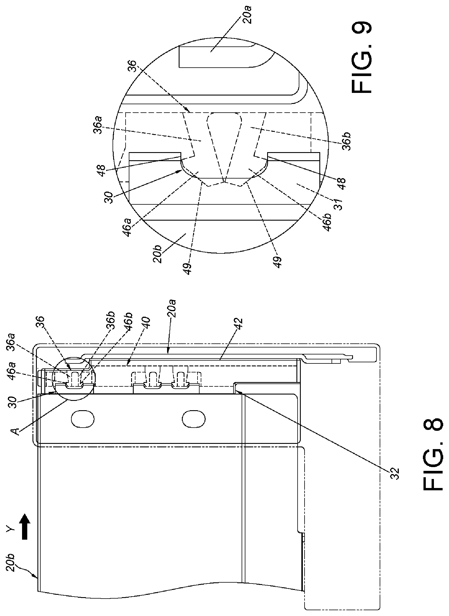
Foreign Application Data
| Date | Code | Application Number |
|---|---|---|
| Mar 15, 2019 | TW | 108109209 |
Claims
1-10. (canceled)
11. A connecting device connected to a first wall of a furniture piece and selectively mounting a second wall or a third wall to the first wall of the furniture piece, the first wall being longitudinally arranged, the connecting device comprising: a base portion connected to the first wall of the furniture piece, the base portion comprising a surface and a space adjacent to the surface, the space being concaved from the surface; at least one engaging arm arranged inside the space of the base portion, the at least one engaging arm being substantially transversely arranged with respect to the first wall, the at least one engaging arm being arranged with an engaging portion, and the at least one engaging arm not exceeding the surface; and an auxiliary portion with at least one fastening feature unmovable relative to the base portion, the auxiliary portion being substantially perpendicularly connected to the base portion, the auxiliary portion exceeding the surface of the base portion by a predetermined distance; wherein a mounting portion of the second wall of the furniture piece is detachably mounted to the engaging portion when the second wall is connected to the first wall with the connecting device; wherein the third wall is capable of connecting to the first wall through the connecting device when the second wall is not connected to the connecting device, when the third wall is connected to the first wall with the connecting device, an end of the third wall of the furniture piece abuts against the surface of the base potion without interference with the engaging portion of the at least one engaging arm, leading the at least one fastening feature of the auxiliary portion to correspond to at least one corresponding fastening feature of the third wall, such that a fastening member is fastened to the at least one corresponding fastening feature of the third wall via the at least one fastening feature of the auxiliary portion.
12. The connecting device of claim 11, wherein at least one portion of the connecting device is made of a plastic material.
13. The connecting device of claim 11, wherein the base portion is fixed to the first wall of the furniture piece via at least one connecting feature.
14. The connecting device of claim 11, wherein the first wall of the furniture piece comprises a first portion and a second portion opposite to the first portion, and the base portion is connected and adjacent to the second portion.
15. The connecting device of claim 11, further comprising a guiding portion, the guiding portion being a curved surface or an inclined surface, wherein when the second wall of the furniture piece has a mounting error with respect to the first wall of the furniture piece, the second wall of the furniture piece is guided and corrected by the guiding portion, so as to facilitate the mounting portion to be mounted to the engaging portion.
16. The connecting device of claim 11, wherein the mounting portion is arranged and adjacent to an end portion of the second wall.
17. The connecting device of claim 16, wherein the mounting portion is a hole, when the mounting portion is mounted to the engaging portion, the engaging portion passes through the hole and is engaged at a mounting end of the hole.
18. The connecting device of claim 11, wherein the surface is substantially a plane.
19. (canceled)
20. The connecting device of claim 11, wherein the mounting portion protrudes from the end portion of the second wall, and an accommodating space is formed between the mounting portion and the end portion of the second wall to accommodate the engaging portion.
21. The connecting device of claim 11, wherein a continuously wall surrounds the space, a height of the continuously wall is constant, the at least one engaging arm arranged inside the space is connected to a bottom of the space, a length of the at least one engaging arm does not exceed the height of the continuously wall, such that the at least one engaging arm does not exceed the surface.
Description
BACKGROUND OF THE INVENTION
1. Field of the Invention
[0001] The present invention relates to a connecting device, and more particularly, to a connecting device which connects two walls of a furniture piece.
2. Description of the Prior Art
[0002] As shown in the US patent with U.S. Pat. No. 8,998,356 B2, a fastening device for connecting two wall parts of a furniture piece is disclosed, and more particularly, the fastening device is for connecting a rear wall to a side wall of a drawer. In the aforesaid US patent, a wall part of the fastening device has at least one locking projection which is resiliently movable about a virtual spring axis, and the locking projection can be locked, preferably detachably locked, into a locking receiver fastened to or formed on the other wall part. The virtual spring axis of the locking projection is provided transversely, preferably substantially perpendicularly, relative to a wall of the wall part. The locking receiver is formed on the other wall part as an opening. A virtual normal of the opening is substantially parallel to the virtual spring axis of the resilient locking projection.
[0003] However, with different market demands, how to develop related products to provide more choices in the market has become an issue that cannot be ignored. Furthermore, the fastening device of the aforesaid US patent is configured to barely protrude from a plane (shown in FIG. 3a of the US patent with U.S. Pat. No. 8,998,356 B2), a corresponding wall is arranged with a combining element which is bent correspondingly to be connected to the fastening device. It is apparently that the arrangement is unfavorably for installing a solid wall (such as a wood wall), and extra accessories are required for the installation.
SUMMARY OF THE INVENTION
[0004] According to one aspect of the present invention, a connecting device adapted to connect a first wall and a second wall of a furniture piece is disclosed. The connecting device includes a base portion and at least one engaging arm. The base portion is connected to the first wall of the furniture piece. The at least one engaging arm is arranged at the base portion. The at least one engaging arm is resiliently movable around a hypothetical axis. The at least one engaging arm is arranged with an engaging portion. The hypothetical axis is substantially parallel to the first wall. The second wall of the furniture piece is mountable to the engaging portion along a mounting direction via a mounting portion. The mounting direction is substantially perpendicular to the hypothetical axis.
[0005] Preferably, at least one portion of the connecting device is made of a plastic material.
[0006] Preferably, the first wall of the furniture piece includes a first portion and a second portion opposite to the first portion, and the base portion is connected and adjacent to the second portion.
[0007] Preferably, the mounting portion is arranged and adjacent to an end portion of the second wall.
[0008] Preferably, the mounting portion is detachably mounted to the engaging portion.
[0009] Preferably, the base portion includes a surface and a space adjacent to the surface, the at least one engaging arm is arranged inside the space, and a length of the at least one engaging arm does not exceed the surface.
[0010] Preferably, the mounting portion protrudes from the end portion of the second wall, and an accommodating space is formed between the mounting portion and the end portion of the second wall to accommodate the engaging portion.
[0011] Preferably, the surface is substantially a plane.
[0012] Preferably, the connecting device further includes an auxiliary portion substantially perpendicularly connected to the base portion, wherein the auxiliary portion includes at least one fastening feature provided to be inserted by a fastening member.
[0013] Preferably, the connecting device further includes a guiding portion being a curved surface or an inclined surface, wherein when the second wall of the furniture piece has a mounting error with respect to the first wall of the furniture piece, the second wall of the furniture piece is guided and corrected by the guiding portion to facilitate the mounting portion to be mounted to the engaging portion.
[0014] According to another aspect of the present invention, a connecting device adapted to a first wall of a furniture piece is disclosed. The first wall is longitudinally arranged. The connecting device includes a base portion, at least one engaging arm and an auxiliary portion. The base portion is connected to the first wall of the furniture piece. The base portion includes a surface and a space adjacent to the surface. The at least one engaging arm is arranged inside the space of the base portion. The at least one engaging arm is substantially transversely arranged with respect to the first wall. The at least one engaging arm is arranged with an engaging portion. The auxiliary portion is substantially perpendicularly connected to the base portion, and the auxiliary portion exceeds the surface of the base portion by a predetermined distance. A second wall of the furniture piece is detachably mounted to the engaging portion via a mounting portion. The auxiliary portion includes at least one fastening feature. When the mounting portion of the second wall of the furniture piece is detached from the engaging portion, an end of another second wall of the furniture piece is capable of abutting against the surface of the base potion. The least one fastening feature is provided to be inserted by a fastening member, such that the another second wall of the furniture piece is fixed to the auxiliary portion.
[0015] Preferably, the mounting portion is a hole. When the mounting portion is mounted to the engaging portion, the engaging portion passes through the hole and is engaged at a mounting end of the hole.
[0016] Preferably, the at least one engaging arm does not exceed the surface of the base portion.
[0017] These and other objectives of the present invention will no doubt become obvious to those of ordinary skill in the art after reading the following detailed description of the preferred embodiment that is illustrated in the various figures and drawings.
BRIEF DESCRIPTION OF THE DRAWINGS
[0018] FIG. 1 is a three-dimensional diagram showing a furniture piece being mounted to a cabinet via a slide rail assembly according to an embodiment of the present invention.
[0019] FIG. 2 is a three-dimensional diagram showing a slide rail of the slide rail assembly capable of carrying the furniture piece according to the embodiment of the present invention.
[0020] FIG. 3 is an exploded diagram showing a connecting device connecting a first wall to a second wall of the furniture piece mounted on the slide rail assembly according to the embodiment of the present invention.
[0021] FIG. 4 is a diagram showing the connecting device connecting to the first wall of the furniture piece mounted on the slide rail assembly according to the embodiment of the present invention.
[0022] FIG. 5 is a diagram showing the second wall of the furniture piece mounting to the first wall of the furniture piece along a direction according to the embodiment of the present invention.
[0023] FIG. 6 is a diagram showing the second wall of the furniture piece continued to be moved toward the first wall of the furniture piece along the direction according to the embodiment of the present invention.
[0024] FIG. 7 is an enlarged view of a portion A of FIG. 6.
[0025] FIG. 8 is a diagram showing the second wall of the furniture piece further moved toward the first wall of the furniture piece along the direction according to the embodiment of the present invention.
[0026] FIG. 9 is an enlarged view of a portion A of FIG. 8.
[0027] FIG. 10 is a diagram showing the second wall of the furniture piece being connected to the first wall via the connecting device according to the embodiment of the present invention.
[0028] FIG. 11 is an enlarged view of a portion A of FIG. 10.
[0029] FIG. 12 is a diagram showing a mounting error between the first wall and the second wall of the furniture piece according to the embodiment of the present invention.
[0030] FIG. 13 is an enlarged view of a portion A of FIG. 12.
[0031] FIG. 14 is a diagram showing the mounting error between the first wall and the second wall of the furniture piece capable of being guided and corrected by a guiding portion of the connecting device according to the embodiment of the present invention.
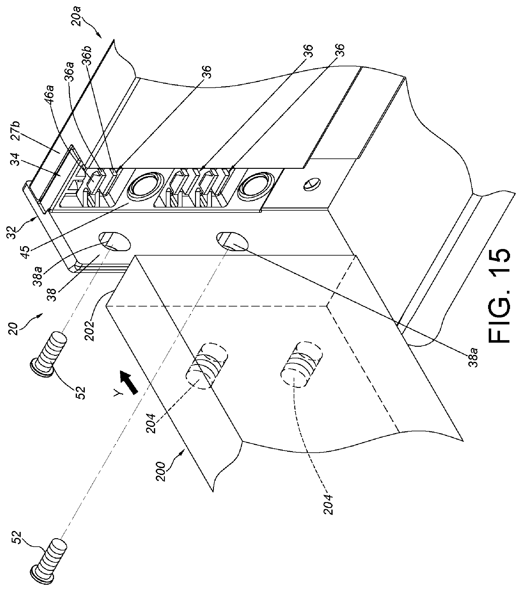
[0032] FIG. 15 is a diagram showing another second wall of the furniture piece capable of being mounted to the first wall via the connecting device according to another embodiment of the present invention.
[0033] FIG. 16 is a diagram showing the another second wall of the furniture piece which has been mounted to the first wall at a view angle according to the another embodiment of the present invention.
[0034] FIG. 17 is a diagram showing the another second wall of the furniture piece which has been mounted to the first wall at another view angle according to the another embodiment of the present invention.
DETAILED DESCRIPTION
[0035] In the following detailed description of the embodiments, the phrase "substantially perpendicular" or "substantially perpendicularly" refers that a member/feature is configured to be perpendicular relative to the other member/feature. However, due to manufacturing tolerance or other factors, the member/feature is not perfectly perpendicular relative to the other member/feature. For example, an included angle between the member/feature and the other member/feature ranging from 85 degrees to 95 degrees and an included angle between the member/feature and the other member/feature ranging from 88 degrees to 92 degrees are within the scope of the present invention. The phrase "substantially parallel" refers that a member/feature is configured to be parallel relative to the other member/feature. However, due to manufacturing tolerance or other factors, the member/feature is not perfectly parallel relative to the other member/feature. For example, an included angle between the member/feature and the other member/feature less than 5 degrees and an included angle between the member/feature and the other member/feature less than 2 degrees are within the scope of the present invention. The phrase "substantially a plane" refers that a member/feature is configured to be a plane. However, due to manufacturing tolerance or other factors, the member/feature is not a perfect plane. The meaning of the phrase "substantially transversely" is similar to that of the phrase "substantially perpendicularly", and thus does not repeated herein.
[0036] As shown in FIG. 1, a furniture piece 20 can be mounted to a cabinet 23 via a pair of slide rail assemblies 22. For example, the furniture piece 20 can be a drawer, but the present invention is not limited thereto.
[0037] As shown in FIG. 2, each of the slide rail assemblies 22 includes a fixed rail 24 and a movable rail 26 longitudinally movable relative to the fixed rail 24. The furniture piece 20 includes a plurality of walls, such as a first wall 20a and a second wall 20b. The first wall 20a is carried by the movable rail 26, such that the furniture piece 20 can be moved along the movable rail 26 relative to the fixed rail 24 via the first wall 20a. In the embodiment, the first wall 20a is a side wall and is longitudinally arranged, the second wall 20b is a rear wall and is transversely arranged with respect to the first wall 20a, but the present invention is not limited thereto. The first wall 20a of the furniture piece 20 includes a first portion 27a and a second portion 27b opposite to the first portion 27a. The first portion 27a is a front portion, and the second portion 27b is a rear portion. Furthermore, the second wall 20b has two end portions opposite to each other. The phrase "longitudinally movable"/"longitudinally arranged" refers a member/feature is movable/arranged along a length direction of the fixed rail 24.
[0038] As shown in FIG. 3, the second wall 20b is arranged with at least one mounting portion 30. Preferably, the at least one mounting portion 30 is arranged and adjacent to the end portion 28 of the second wall 20b. Preferably, the at least one mounting portion 30 protrudes from the end portion 28 of the second wall 20b. For example, the at least one mounting portion 30 is a protruding structure with curved contour. An accommodating space 31 is formed between an inner side of the protruding structure and the end portion 28 of the second wall 20b. At least one hole or slot communicating with the accommodating space 31 is formed at a middle portion of the protruding structure. The least one hole or slot has a width W. In the embodiment, a plurality of holes communicating with the accommodating space 31 are formed at the middle portion of the protruding structure, which is only for exemplary and the present invention is not limited thereto.
[0039] Furthermore, the present invention provides a connecting device 32 adapted to connect the first wall 20a and the second wall 20b of the furniture piece 20. Preferably, at least one portion of the connecting device 32 is made of a plastic material. In the embodiment, the connecting device 32 is made of a plastic material, but the present invention is not limited thereto.
[0040] As shown in FIG. 3 and FIG. 4, the connecting device 32 includes a base portion 34 and at least one engaging arm 36. Preferably, the connecting device 32 further includes an auxiliary portion 38.
[0041] The base portion 34 is connected to the first wall 20a of the furniture piece 20. Preferably, the base portion 34 is connected and adjacent to the second portion 27b of the first wall 20a of the furniture piece 20. Specifically, the base portion 34 includes at least one connecting feature. In the embodiment, a first side (such as a rear side) of the base portion 34 is connected to (fixedly connected to or detachably connected to) the second portion 27b of the first wall 20a of the furniture piece 20. For example, in the embodiment, the base portion 34 is connected to a plate 42 (shown in FIG. 3) via at least one fixing member 41 (such as screw or rivet), such that the plate 42 is attached to the first side of the base portion 34. The plate 42 includes at least one connecting feature, such as a first connecting feature 40a and a second connecting feature 40b, to be fixed to at least one corresponding feature of the first wall 20a of the furniture piece 20, such as a first corresponding feature 44a and a second corresponding feature 44a (shown in FIG. 3), via engaging, inserting or fastening. In other embodiment, the base portion 34 can be fixed to the first wall 20a of the furniture piece 20 via at least one screw or rivet. Therefore, the connection between the base portion 34 and the first wall 20a of the furniture piece 20 is not limited. Furthermore, the connecting features 40a, 40b and the corresponding feature 44a, 44b can be cooperated convex structures and concave structures, or cooperated convex structures and hole structures, and the present invention is not limited thereto. Furthermore, the number and the position of the connecting feature and the corresponding feature are only exemplary, and the present invention is not limited thereto.
[0042] The at least one engaging arm 36 is arranged at the base portion 34, and the at least one engaging arm 36 is substantially transversely arranged with respect to the first wall 20a. In the embodiment, the at least one engaging arm 36 is arranged at a second side (such as a front side) opposite to the first side of the base portion 34, which is only exemplary. The at least one engaging arm 36 is resiliently movable around a hypothetical axis X. The hypothetical axis X is substantially parallel to the first wall 20a which is longitudinally arranged.
[0043] Preferably, the at least one engaging arm 36 can be three pairs of engaging arms, which is only exemplary and the number of the engaging arm 36 is not limited thereto. Each pair of the engaging arms 36 includes a first engaging arm 36a and a second engaging arm 36b. The structures of the first engaging arm 36a and the second engaging arm 36b are substantially identical. The first engaging arm 36a and the second engaging arm 36b are separated from each other by a distance G. The distance G is less than the width W. Furthermore, each of the first engaging arm 36a and the second engaging arm 36b is arranged with an engaging portion. For example, the first engaging arm 36a is arranged with a first engaging portion 46a, and the second engaging arm 36b is arranged with a second engaging portion 46b. Preferably, the structures of the first engaging portion 46a and the second engaging portion 46b are configured to be symmetrical. Each of the first engaging portion 46a and the second engaging portion 46b includes a guiding segment 49. The guiding segment 49 can be arranged as an inclined surface or a curved surface. Furthermore, the first engaging portion 46a can be a hook facing upwardly, and the second engaging portion 46b can be a hook facing downwardly (shown in FIG. 5). However, the directions of the first engaging portion 46a and the second engaging portion 46b are not limited thereto.
[0044] Preferably, the base portion 34 includes a surface 45 and a space 47 adjacent to the surface 45. The surface 45 is substantially a plane. The space 47 is formed at the base 34, and an opening of the space 47 is located at the surface 45. The at least one engaging arm 36 is arranged inside the space 47, and a length of the at least one engaging arm 36 does not exceed the surface 45. Furthermore, the auxiliary portion 38 is substantially perpendicularly connected to the base portion 34, and the auxiliary portion 38 exceeds the surface 45 of the base portion 34 by a predetermined distance. The auxiliary portion 38 includes at least one fastening feature 38a to be inserted by a fastening member.
[0045] As shown in FIG. 5, the second wall 20b of the furniture piece 20 is mountable to the at least one engaging arm 36 along a mounting direction Y via the at least one mounting portion 30. The mounting direction Y is substantially perpendicular to the hypothetical axis X, and the mounting direction Y is substantially parallel to the at least one engaging arm 36 which is transversely arranged.
[0046] As shown in FIG. 6 and FIG. 7, when the second wall 20b of the furniture piece 20 is moved along the mounting direction Y to a predetermined distance and is close to the first wall 20a, the mounting end 48 of the at least one mounting portion 30 contacts the guiding segments 49 of the first engaging portion 46a and the second engaging portion 46b of the at least one engaging arm 36, wherein a distance between the two mounting ends 48 defines the width W.
[0047] As shown in FIG. 8 and FIG. 9, when the second wall 20b of the furniture piece 20 is continued to be moved along the mounting direction Y, the mounting end 48 of the at least one mounting portion 30 pushes against the guiding segments 49 of the first engaging portion 46a and the second engaging portion 46b of the at least one engaging arm 36 to drive the first engaging arm 36a and the second engaging arm 36b to move resiliently around the hypothetical axis X, such that the first engaging arm 36a and the second engaging arm 36b are approached toward each other. Meanwhile, the first engaging arm 36a and the second engaging arm 36b are in a state of accumulating a resilient force, and the end portions of the first engaging arm 36a and the second engaging arm 36b move slightly into the accommodating space 31.
[0048] As shown in FIG. 10 and FIG. 11, when the second wall 20b of the furniture piece 20 is further moved along the mounting direction Y, the mounting end 48 of the at least one mounting portion 30 further passes the first engaging portion 46a and the second engaging portion 46b of the at least one the engaging arm 36, such that the first engaging portion 46a and the second engaging portion 46b of the at least one engaging arm 36 are accommodated in the accommodating space 31. Once the mounting end 48 of the at least one mounting portion 30 passes the first engaging portion 46a and the second engaging portion 46b, the first engaging arm 36a and the second engaging arm 36b release the resilient force, such that the first engaging arm 36a and the second engaging arm 36b return to the state that the first engaging arm 36a and the second engaging arm 36b are spaced by the distance G. As such, the first engaging portion 46a and the second engaging portion 46b engage with the mounting end 48 of the at least one mounting portion 30 and abut against a wall surface of the mounting end 48 of the at least one mounting portion 30. Therefore, the second wall 20b can be fixedly connected to the first wall 20a via the connecting device 32 in a tool-free manner.
[0049] Moreover, the at least one mounting portion 30 of the connecting device 32 can be detachably disengaged from the first engaging portion 46a and the second engaging portion 46b. For example, when a user applies a force to deform the first engaging arm 36a and the second engaging arm 36b (as the state shown in FIG. 9), the first engaging portion 46a and the second engaging portion 46b are no longer engaged with the mounting end 48 of the at least one mounting portion 30, such that the second wall 20b can be detached from the first wall 20a along a detaching direction opposite to the mounting direction Y.
[0050] As shown in FIG. 12 and FIG. 13, the connecting device 32 can further include a guiding portion 50, and the guiding portion 50 can be a curved surface or an inclined surface. When the second wall 20b of the furniture piece 20 has a mounting error B with respect to the first wall 20a, the second wall 20b of the furniture piece 20 can be guided and corrected by the guiding portion 50 (as shown in FIG. 14), which can facilitate the at least one mounting portion 30 to be mounted to the engaging portion (such as the first engaging portion 46a and the second engaging portion 46b) of the engaging arm 36 (as shown in FIG. 11).
[0051] For example, during the second wall 20b of the furniture piece 20 being moved toward the first wall 20a along the mounting direction Y, if the second wall 20b of the furniture piece 20 has the mounting error B with respect to the first wall 20a (as shown in FIG. 12), with the mounting end 48 of the mounting portion 30 contacting the guiding portion 50 (as shown in FIG. 13), the second wall 20b of the furniture piece 20 can be guided and corrected (as shown in FIG. 14). As such, the mounting end 48 of the at least one mounting portion 30 can be successfully engaged to the first engaging portion 46a and the second engaging portion 46b (as shown in FIG. 11).
[0052] As shown in FIG. 15, FIG. 16 and FIG. 17, when the second wall 20b of the furniture piece 20 is detached from the first engaging portion 46a and the second engaging portion 46b via the mounting portion 30, another type of plate (such as a wood plate or other solid plate) can be used to replace the second wall 20b. For example, an end 202 of the another second wall 200 used in the furniture piece 20 is capable of abutting against the surface 45 of the base potion 34 of the connecting device 32, at least one fastening feature 38a is provided to be inserted by the at least one fastening member 52 and the fastening member 52 is fastened to at least one corresponding fastening feature 204 of the another second wall 200, such that the another second wall 200 is fixed to the auxiliary portion 38, and the another second wall 200 can be connected to the first wall 20a thereby.
[0053] Therefore, the connecting device 32 is capable of connecting two types of second walls (for example, the aforesaid second wall 20b and the another second wall 200) with different structures to the first wall 20a without using other accessories, which can satisfy different market demands.
[0054] To sum up, the connecting device 32 according to the embodiment of the present invention includes features as follows.
[0055] First, the second wall 20b of the furniture piece 20 can be connected to the first wall 20a in a tool-free manner, which facilitates and eases the assembling and detachment.
[0056] Second, the at least one engaging arm 36 is substantially transversely arranged with respect to the first wall 20a which is longitudinally arranged, and the mounting direction Y of the second wall 20b is substantially parallel to the engaging arm 36 which is substantially transversely arranged. As such, it facilitates a user to connect the second wall 20b to the first wall 20a.
[0057] Third, the connecting device 32 is capable of connecting two types of second walls (20b and 200, shown in FIG. 3 and FIG. 0.15) with different structures to the first wall 20a without using other accessories, which can satisfy different market demands.
[0058] Those skilled in the art will readily observe that numerous modifications and alterations of the device and method may be made while retaining the teachings of the invention. Accordingly, the above disclosure should be construed as limited only by the metes and bounds of the appended claims.
* * * * *
D00000
D00001
D00002
D00003
D00004
D00005
D00006
D00007
D00008
D00009
D00010
D00011
D00012

XML
uspto.report is an independent third-party trademark research tool that is not affiliated, endorsed, or sponsored by the United States Patent and Trademark Office (USPTO) or any other governmental organization. The information provided by uspto.report is based on publicly available data at the time of writing and is intended for informational purposes only.
While we strive to provide accurate and up-to-date information, we do not guarantee the accuracy, completeness, reliability, or suitability of the information displayed on this site. The use of this site is at your own risk. Any reliance you place on such information is therefore strictly at your own risk.
All official trademark data, including owner information, should be verified by visiting the official USPTO website at www.uspto.gov. This site is not intended to replace professional legal advice and should not be used as a substitute for consulting with a legal professional who is knowledgeable about trademark law.