Centrifugal Pump
HONDA; Yoshihiko ; et al.
U.S. patent application number 16/814041 was filed with the patent office on 2020-09-17 for centrifugal pump. This patent application is currently assigned to AISAN KOGYO KABUSHIKI KAISHA. The applicant listed for this patent is AISAN KOGYO KABUSHIKI KAISHA. Invention is credited to Yoshihiko HONDA, Naoki SHIRAI, Hironori SUZUKI.
| Application Number | 20200291956 16/814041 |
| Document ID | / |
| Family ID | 1000004702963 |
| Filed Date | 2020-09-17 |


| United States Patent Application | 20200291956 |
| Kind Code | A1 |
| HONDA; Yoshihiko ; et al. | September 17, 2020 |
Centrifugal Pump
Abstract
A centrifugal pump includes an impeller and a housing defining a pump chamber that houses the impeller therein. The housing includes an inlet passage in fluid communication with the pump chamber and an outside of the housing. The inlet passage includes a connection passage part having a cylindrical shape extending from the pump chamber and a main passage part having a cylindrical shape connected to the connection passage part, so as to form a bent shape. A central axis of the main passage part is parallel to a reference plane that includes a central axis of the connection passage part. A flow direction of a fluid parallel the central axis of the main passage part is partly the same as the rotational direction of the impeller in a plan view along an axis of the impeller.
| Inventors: | HONDA; Yoshihiko; (Obu-shi, JP) ; SUZUKI; Hironori; (Obu-shi, JP) ; SHIRAI; Naoki; (Toyohashi-shi, JP) | ||||||||||
| Applicant: |
|
||||||||||
|---|---|---|---|---|---|---|---|---|---|---|---|
| Assignee: | AISAN KOGYO KABUSHIKI
KAISHA Obu-shi JP |
||||||||||
| Family ID: | 1000004702963 | ||||||||||
| Appl. No.: | 16/814041 | ||||||||||
| Filed: | March 10, 2020 |
| Current U.S. Class: | 1/1 |
| Current CPC Class: | F04D 29/42 20130101; F04D 17/10 20130101 |
| International Class: | F04D 29/42 20060101 F04D029/42; F04D 17/10 20060101 F04D017/10 |
Foreign Application Data
| Date | Code | Application Number |
|---|---|---|
| Mar 12, 2019 | JP | 2019-044517 |
Claims
1. A centrifugal pump, comprising: an impeller configured to rotate about a rotational axis in a rotational direction; and a housing defining a pump chamber within which the impeller is disposed, wherein the housing includes an inlet passage and an outlet passage, wherein each of the inlet passage and the outlet passage is in fluid communication with the pump chamber and an outside of the housing, wherein: the pump chamber has an inflow part at an upstream end thereof, the inflow part of the pump chamber has an inflow end at an upstream end thereof and has a hollow tapered shape with a width that continuously decreases moving toward the inflow end, the inlet passage includes a connection passage part having a cylindrical shape coupled to the inflow end of the inflow part and a main passage part having a cylindrical shape connected to the connection passage part so as to form a bent shape, and a central axis of the main passage part is oriented parallel to a reference plane that includes a central axis of the connection passage part such that a flow direction of a fluid along the central axis of the main passage part is partly the same as the rotational direction of the impeller in a plan view along the rotational axis of the impeller.
2. The centrifugal pump of claim 1, wherein: the housing includes a first pipe part defining the main passage part therein and a second pipe part defining the connection passage part therein, the first pipe part and the second pipe part are coupled to each other to form a first connection part therebetween, and a corner is formed at a part of the first connection part closer to the reference plane in the plan view.
3. The centrifugal pump of claim 1, wherein a part of the main passage part is in direct fluid communication with the inflow part.
4. The centrifugal pump of claim 1, wherein: the outlet passage has a cylindrical shape extending in a tangential direction from the pump chamber such that a flow direction of the fluid along a central axis of the outlet passage is substantially the same as the rotational direction of the impeller at a second connection part between the outlet passage and the pump chamber in the plan view, and the central axis of the outlet passage is oriented parallel to the central axis of the main passage part in the plan view.
5. A centrifugal pump, comprising: an impeller configured to be rotated about a rotational axis in a rotational direction; and a housing defining a pump chamber housing the impeller therein, wherein the housing includes an inlet passage and an outlet passage, wherein each of the inlet passage and the outlet passage is in fluid communication with the pump chamber and an outside of the housing, wherein: the pump chamber has an inflow part at an upstream end thereof, the inflow part has an inflow end at an upstream end thereof and has a hollow tapered shape with a width that continuously decreases moving toward the inflow end, the inlet passage includes a connection passage part having a cylindrical shape coupled to the inflow end of the inflow part and a main passage part having a cylindrical shape connected to the connection passage part so as to form a bent shape, a central axis of the main passage part is oriented parallel to a reference plane that includes a central axis of the connection passage part, the housing include a first pipe part defining the main passage part therein such that the first pipe part includes a front wall and a rear wall disposed rearward of the front wall relative to the rotational direction in a plan view along the rotational axis of the impeller, and a first distance between the reference plane and the front wall is greater than a second distance between the reference plane and the rear wall in the plan view.
6. The centrifugal pump of claim 5, wherein: the housing includes a second pipe part defining the connection passage part therein, the first pipe part and the second pipe part are coupled to each other to form a first connection part therebetween, and a corner is formed at a part of the first connection part closer to the reference plane in the plan view.
7. The centrifugal pump of claim 5, wherein a part of the main passage part is in direct fluid communication with the inflow part.
8. The centrifugal pump of claim 5, wherein: the outlet passage has a cylindrical shape extending in a tangential direction from the pump chamber, such that a flow direction of a fluid along a central axis of the outlet passage is substantially the same as the rotational direction of the impeller at a second connection part between the outlet passage and the pump chamber in the plan view, and the central axis of the outlet passage is oriented parallel to the central axis of the main passage part in the plan view.
Description
CROSS-REFERENCE TO RELATED APPLICATIONS
[0001] This application claims priority to Japanese patent application serial number 2019-044517, filed Mar. 12, 2019, which is hereby incorporated herein by reference in its entirety for all purposes.
STATEMENT REGARDING FEDERALLY SPONSORED RESEARCH OR DEVELOPMENT
[0002] Not applicable.
BACKGROUND
[0003] This disclosure relates generally to centrifugal pumps.
[0004] One type of centrifugal pump includes an impeller rotated by a motor and a housing defining a pump chamber therein. The impeller is housed in the pump chamber and includes a main plate having a substantially circular shape and a plurality of blades on the main plate. The housing has an inlet port and an outlet port that each provide fluid communication between the inside and the outside of the pump chamber. The inlet port extends upward from the pump chamber and is coaxially aligned with the impeller.
[0005] Japanese Laid-Open Patent Publication No. 2015-190321 discloses another type of centrifugal pump in which the inlet port of the housing is bent in an L-shape. In particular, an inlet passage within the inlet port is divided into a connection passage part and a main passage part. The connection passage part extends upward from the pump chamber. The main passage part is connected to an upstream end of the connection passage part at a right angle.
BRIEF SUMMARY
[0006] In one aspect of this disclosure, a centrifugal pump includes an impeller configured to be rotated about an axis of rotation in a rotational direction and a housing defining a pump chamber that houses the impeller therein. The housing includes an inlet passage and an outlet passage, each of which provides fluid communication between the pump chamber and the outside of the housing. The pump chamber has an inflow part at an upstream end thereof. The inflow part has an inflow end at an upstream end thereof and may have a hollow tapered shape with a width that continuously decreasing toward the inflow end. The inlet passage includes a connection passage part that may have a cylindrical shape coupled to the inflow end of the inflow part and a main passage part that may have a cylindrical shape connected to the connection passage part, so as to form a bent shape. A central axis of the main passage part is oriented parallel to a reference plane that includes a central axis of the connection passage part. The main passage part is configured such that a flow direction of a fluid parallel to the central axis of the main passage part is the same as at least one part of the rotational direction of the impeller in a plan view along the axis of rotation of the impeller.
[0007] In accordance with this aspect, the main passage part is configured such that a flow direction of fluid along the central axis of the main passage part is same as the rotational direction of the impeller in at least one place. Thus, when fluid flowing linearly in the main passage part enters the connection passage part, the fluid rotates in a same direction as the rotational direction of the impeller while flowing through the connection passage part. Accordingly, the fluid can smoothly flow from the connection passage part into the inflow part of the pump chamber. Accordingly, non-uniform distribution of the fluid on the impeller can be reduced, thereby improving the performance of the centrifugal pump.
BRIEF DESCRIPTION OF THE DRAWINGS
[0008] For a detailed description of the preferred embodiments of the present teaching, reference will now be made to the accompanying drawings.
[0009] FIG. 1 is a partial cross-sectional plan view of a first embodiment of a centrifugal pump.
[0010] FIG. 2 is a cross-sectional view of the centrifugal pump of FIG. 1, taken along section II-II of FIG. 1.
[0011] FIG. 3 is a cross-sectional view of the centrifugal pump of FIG. 1, taken along section III-III of FIG. 1.
[0012] FIG. 4 is a cross-sectional view of a second embodiment of a centrifugal pump.
[0013] FIG. 5 is a cross-sectional view of a third embodiment of a centrifugal pump.
[0014] FIG. 6 is a cross-sectional view of a fourth embodiment of a centrifugal pump.
[0015] FIG. 7 is a partial cross-sectional plan view of a fifth embodiment of a centrifugal pump.
DETAILED DESCRIPTION
[0016] The following discussion is directed to various exemplary embodiments. However, one skilled in the art will understand that the examples disclosed herein have broad application, and that the discussion of any embodiment is meant only to be exemplary of that embodiment, and not intended to suggest that the scope of the disclosure, including the claims, is limited to that embodiment.
[0017] As previously described, Japanese Laid-Open Patent Publication No. 2015-190321 discloses a centrifugal pump in which the main passage part of the inlet is connected to the upstream end of the connection passage part of the inlet at a right angle. Consequently, a central axis of the main passage part is oriented perpendicular to a central axis of the connection passage part. Thus, fluid flowing through the main passage part tends to flow into the far side of the connection passage part. As a result, the volume of flow of the fluid proximal the far side of the connection passage part is typically greater than the volume of flow of the fluid proximal the near side of the connection passage part. This causes the fluid to enter the pump chamber in an imbalanced manner, such that the fluid is not dispersed uniformly over the impeller. Such lack of uniformity in the fluid distribution decreases the performance of the centrifugal pump. Therefore, there has been a need for an improved centrifugal pump.
[0018] A first embodiment will be described with reference to FIGS. 1 to 3. The first embodiment of a centrifugal pump 10 is a purge pump mounted on a vehicle, such as an automobile. The purge pump is configured to compensate for a shortage of purge gas flowing from a canister to an air intake passage of an internal combustion engine. In each drawing, directions of the centrifugal pump 10 are illustrated for convenience of explanation, however, these directions do not limit a mounting direction of the centrifugal pump 10 on the vehicle.
[0019] As shown in FIG. 2, the centrifugal pump 10 includes a housing 11 having a substantially hollow cylindrical shape. The housing 11 may be made from a resin material, a metal material, or other suitable material. The centrifugal pump 10 also includes a pump section 12 at an upper portion of the housing 11 and a motor section 14 positioned below the pump section 12. The motor section 14 has a brushless motor and includes a rotational shaft 15 extending in the vertical direction. The motor section 14 may also be referred to herein as "motor."
[0020] The housing 11 defines a pump chamber 17 in an upper portion thereof. The pump chamber 17 has a hollow short cylindrical shape and is coaxially aligned with the rotational shaft 15 of the motor section 14. The housing 11 is divided into an upper housing member 11a and a lower housing member 11b coupled to the upper housing member 11a. The pump chamber 17 is defined by the upper housing member 11a and the lower housing member 11b. The rotational shaft 15 of the motor section 14 penetrates the lower housing member 11b so as to protrude into the pump chamber 17.
[0021] The pump chamber 17 has an inflow part 18 positioned at a center of an upper portion of the pump chamber 17 and a volute part 19 disposed at an outer circumferential part of the pump chamber 17. The inflow part 18 has an inflow end 18a at an upper end thereof, such that fluid flows into the inflow part 18 via the inflow end 18a. The inflow part 18 has a tapered shape with a width that gradually decreases in cross-sectional area moving toward the inflow end 18a, i.e. toward the upstream side.
[0022] The upper housing member 11a includes an inlet port 22 at an upper portion thereof. The inlet port 22 is a tubular defining an inlet passage 23 therein, such that the pump chamber 17 is in fluid communication with the outside of the housing 11 via the inlet passage 23. Details of the inlet passage 23 will be described hereinbelow.
[0023] As shown in FIG. 1, the housing 11 includes an outlet port 27 having a hollow cylindrical shape extending leftward from a front portion of the housing 11. In a plan view of the centrifugal pump 10, the outlet port 27 extends tangentially from an outer circumference of the housing 11, i.e. leftward. The outlet port 27 defines an outlet passage 28 therein, such that the volute part 19 of the pump chamber 17 is in a fluid communication with the outside of the housing 11 via the outlet passage 28.
[0024] As shown in FIG. 2, an impeller 30 is rotatably housed in the pump chamber 17. The impeller 30 includes a main plate 32 and a plurality of blades 34 extending from the main plate 32. The main plate 32 has a substantially circular plate shape in a plan view. In addition, the main plate 32 has a convex part 32a having a truncated conical shape at a central portion of an upper surface thereof. The convex part 32a is coaxially positioned along the main plate 32. The convex part 32a has a shaft hole 33 at a central portion thereof. Shaft hole 33 is coaxially aligned with main plate 32 and rotational shaft 15. The blades 34 protrude upward from the upper surface of the main plate 32 and extend in a substantially radial direction along the upper surface of the main plate 32. Each of the blades 34 has an elongated rectangular shape extending in the radial direction of the impeller 30. A radially inner end of each blade 34 is positioned in a lower portion of the inflow part 18 of the pump chamber 17. The impeller 30 may be made from a resin material, metal material, or other suitable material.
[0025] The rotational shaft 15 of the motor section 14 is inserted into the shaft hole 33 of the impeller 30 and fixably secured thereto. Thus, when the motor section 14 is running, the impeller 30 rotates with the rotational shaft 15. As shown in FIG. 1, in the plan view of the centrifugal pump 10, the impeller 30 rotates about its central axis in a rotational direction R in a clockwise direction.
[0026] When the motor section 14 is driven using electricity supplied from an external power source, the impeller 30 is rotated together with the rotational shaft 15, so that fluid, i.e. purge gas in this embodiment, is suctioned into the pump chamber 17 via the inlet passage 23. The purge gas is pressurized and then discharged into the outflow passage 28 via rotation of the impeller 30. The purge gas may be pumped by the centrifugal pump 10 in this manner.
[0027] As shown in FIG. 2, the inlet passage 23 is divided into a main passage part 24 and a connection passage part 25, each of which has a cylindrical cross-sectional shape. The connection passage part 25 extends upward from the inflow end 18a of the inflow part 18. The main passage part 24 is connected to the connection passage part 25, so as to extend radially outward from the connection passage part 25 and form a bent shape therewith. More specifically, in this embodiment, the main passage part 24 is connected to the connection passage part 25 to form substantially a right angle along one plane, for instance a plane including the left-right and front-rear directions with the main passage part 24 extending rightward. The connection passage part 25 has the same inner diameter as the inflow end 18a. The inner diameter of the main passage part 24 is equal to or greater than the inner diameter of the connection passage part 25. For example, the inner diameter of the main passage part 24 may be about one and a half times greater than the inner diameter of the connection passage part 25.
[0028] FIG. 1 illustrates a reference plane 25s containing a central axis 25c of the connection passage part 25 and extending radially in the right-left direction, and oriented parallel to a central axis 24c of the main passage part 24. In the plan view of the centrifugal pump 10 of FIG. 1, the central axis 24c of the main passage part 24 is positioned in front of (and oriented parallel to) the reference plane 25s. That is, the central axis 24c of the main passage part 24 deviates forward from the reference plane 25s by an offset distance L such that a flow direction F parallel to the central axis 24c is substantially the same as the rotational direction R of the impeller 30 in at least one place in the plan view of the centrifugal pump 10. The central axis 25c of the connection passage part 25 is coaxially aligned with the rotational axis of the impeller 30.
[0029] In the plane view of the centrifugal pump 10, the main passage part 24 is directly connected to the connection passage part 25, on one side of the connection part closer to the reference plane 25s (the rear side in FIG. 1), such that an inner surface 24a of the main passage part 24 and an inner surface 25a of the connection passage part 25 form a sharp corner 26 having a convex shape. The inlet port 22 includes an inclined surface 29, connecting the main passage part 24 to the connection passage part 25, on the other side farther from the reference plane 25s (the front side in FIG. 1), such that the inner surface 24a is gently continued to the inner surface 25a via the inclined surface 29.
[0030] As shown in FIG. 2, the inflow end 18a of the pump chamber 17 is positioned proximal the midpoint between the central axis 24c and a bottom surface 24b of the main passage part 24 in the vertical direction. Due to this arrangement, a part of the main passage part 24 is in direct fluid communication with the inflow part 18. More specifically, a lower end part of the main passage part 24 is in direct fluid communication with the upper end of the inflow part 18.
[0031] As shown in FIG. 1, the outlet port 27 has a hollow cylindrical cross-sectional shape defining the outlet passage 28 therein. The outlet passage 28 extends in a tangential direction from the pump chamber 17, such that a flow direction in the outlet passage 28 is substantially the same as the rotational direction R at a connection portion between the outlet passage 28 and the pump chamber 17. The inlet port 22 extends rightward, and the outlet port 27 extends leftward. So, the central axis 24c of the main passage part 24 is oriented parallel to a central axis 28c of the outlet passage 28. In this embodiment, the plan view of the centrifugal pump 10 corresponds to a view along an axial direction of the pump chamber 17. The term "parallel" may include "substantially parallel."
[0032] In accordance with the first embodiment, the central axis 24c of the main passage part 24 is not included in the reference plane 25s, the plane which includes the central axis 25c of the connection passage part 25, such that the flow direction F along the central axis 24c is substantially the same as the rotational direction R of the impeller 30 in at least one place, in the plan view of the centrifugal pump 10. Thus, when the fluid flowing in the main passage part 24 enters the connection passage part 25, the fluid rotates in a same direction S as the rotational direction R of the impeller 30 while flowing through the connection passage part 25. That is, while the fluid flows through the connection part 25, it has a rotational flow component. As a result, flow of the fluid can smoothly transition from the connection passage part 25 into the inflow part 18 of the pump chamber 17. Accordingly, non-uniform distribution of the fluid on the impeller 30 can be reduced, thereby improving the performance of the centrifugal pump 10.
[0033] As previously described, the main passage part 24 and the connection passage part 25 intersect at the sharp corner 26 on the one side closer to the reference plane 25s. The sharp corner 26 facilitates generation of the rotational flow in the connection passage part 25, thereby improving the performance of the centrifugal pump 10, in comparison with a case where the main passage part 24 gently transitions to the connection passage part 25, without the sharp corner 26.
[0034] A part of the main passage part 24 is in direct fluid communication with the inflow part 18. Thus, a part of the fluid flowing through the main passage part 24 can flow directly into the inflow part 18 of the pump chamber 17, without passing through the connection passage part 25. This reduces the moving distance of a portion of the fluid flow. Accordingly, in comparison with a case where the whole of the main passage part 24 is indirectly connected to the inflow part 18 via the connection passage part 25, the performance of the centrifugal pump 10 can be increased.
[0035] In the plan view of the centrifugal pump 10, the central axis 24c of the main passage part 24 is oriented parallel to the central axis 28c of the outlet passage 28. Thus, in comparison with a case where the central axes 24c, 28c are not oriented parallel with each other in the plan view of the centrifugal pump 10, a pipe can be easily connected to each of the main passage part 24 and the outlet passage 28, thereby improving the mountability of the centrifugal pump 10 on a vehicle, etc. In the plan view of the centrifugal pump 10, the inlet passage 23 may be oriented in the same direction as the outlet passage 28, e.g. leftward in FIG. 1.
[0036] A second embodiment will be described with reference to FIG. 4. The second embodiment is substantially the same as the first embodiment described above, with some differences regarding the inlet passage 23. Thus, while the differences will be described, similar configurations will not be described in the interest of conciseness. As shown in FIG. 4, the bottom surface 24b of the main passage part 24 is even with the inflow end 18a of the pump chamber 17, in the vertical direction. Due to this configuration, the main passage part 24 is indirectly connected, via the connection passage part 25, to the inflow part 18. Thus, the axial length of the connection passage part 25 is longer than that of the first embodiment.
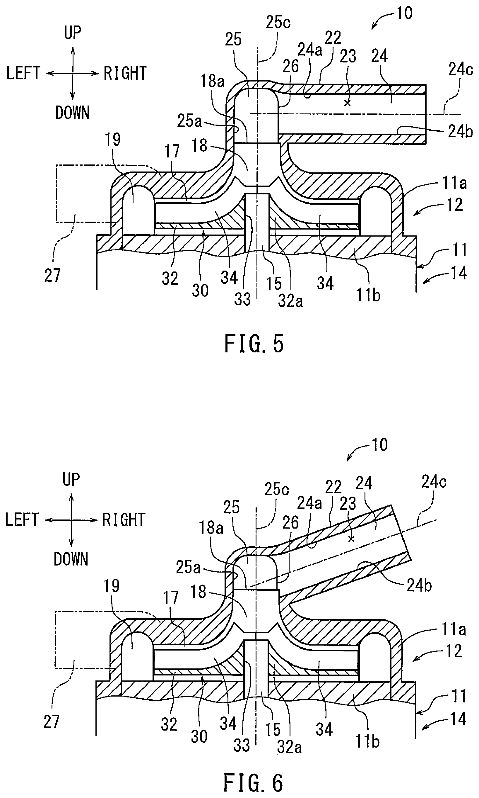
[0037] A third embodiment will be described with reference to FIG. 5. The third embodiment is substantially the same as the first embodiment described above, with some differences regarding the inlet passage 23. Thus, while the differences will be described, similar configurations will not be described in the interest of conciseness. As shown in FIG. 5, the bottom surface 24b of the main passage part 24 is positioned above the inflow end 18a of the pump chamber 17 in the vertical direction. Accordingly, the main passage part 24 is indirectly connected, via the connection passage part 25, to the inflow part 18 such that the axial length of the connection passage part 25 is longer than those of both the first embodiment and the second embodiment.
[0038] A fourth embodiment will be described with reference to FIG. 6. The fourth embodiment is substantially the same as the first embodiment described above, with some differences regarding the inlet passage 23. Thus, while the differences will be described, similar configurations will not be described in the interest of conciseness. As shown in FIG. 6, the main passage part 24 extends obliquely upward, such that an angle formed by the central axis 24c of the main passage part 24 and the central axis 25c of the connection passage part 25 is about 110 degree. The degree of inclination can be set freely based on various requirements, such as a mounting space.
[0039] A fifth embodiment will be described with reference to FIG. 7. The fifth embodiment is substantially the same as the first embodiment described above, with some differences regarding the outlet passage 28. Thus, while the differences will be described, similar configurations will not be described in the interest of conciseness. As shown in FIG. 7, the main passage part 24 extends in the right-left direction, and the outlet passage 28 extends in the front-rear direction, such that the central axis 24c of the main passage part 24 is oriented perpendicular to the central axis 28c of the outlet passage 28 in the plan view of the centrifugal pump 10. The outlet passage 28 may be oriented such that the central axis 28c crosses the central axis 24c at any angle. The term "perpendicular" includes "substantially perpendicular" in this disclosure.
[0040] As stated above, the technique disclosed in this application is not limited to the above-described embodiments. For example, the centrifugal pump 10 may be used for pumping various fluids, such as air, other than the above described purge gas. The brushless motor of the motor section 14 may be replaced with a brushed motor. The centrifugal pump 10 may be composed of the pump section 12 only, such that the rotational shaft 15 is rotated by a driving source that is provided outside the centrifugal pump 10. The impeller 30 may be made from a metal or other material.
* * * * *
D00000
D00001
D00002
D00003
D00004
XML
uspto.report is an independent third-party trademark research tool that is not affiliated, endorsed, or sponsored by the United States Patent and Trademark Office (USPTO) or any other governmental organization. The information provided by uspto.report is based on publicly available data at the time of writing and is intended for informational purposes only.
While we strive to provide accurate and up-to-date information, we do not guarantee the accuracy, completeness, reliability, or suitability of the information displayed on this site. The use of this site is at your own risk. Any reliance you place on such information is therefore strictly at your own risk.
All official trademark data, including owner information, should be verified by visiting the official USPTO website at www.uspto.gov. This site is not intended to replace professional legal advice and should not be used as a substitute for consulting with a legal professional who is knowledgeable about trademark law.