Centrifugal Pump
SUZUKI; Hironori ; et al.
U.S. patent application number 16/818218 was filed with the patent office on 2020-09-17 for centrifugal pump. This patent application is currently assigned to AISAN KOGYO KABUSHIKI KAISHA. The applicant listed for this patent is AISAN KOGYO KABUSHIKI KAISHA. Invention is credited to Yoshihiko HONDA, Hironori SUZUKI.
| Application Number | 20200291954 16/818218 |
| Document ID | / |
| Family ID | 1000004716001 |
| Filed Date | 2020-09-17 |


View All Diagrams
| United States Patent Application | 20200291954 |
| Kind Code | A1 |
| SUZUKI; Hironori ; et al. | September 17, 2020 |
Centrifugal Pump
Abstract
A centrifugal pump includes a housing and an impeller housed in the housing. The impeller has a main plate, a plurality of first blades, and a plurality of second blades. The first blades and the second blades extend radially along the main plate and have the same radial length. Each of the second blades has a low blade part and a high blade part extending radially from a radially outer end of the low blade part. When comparing the first blades and the second blades with each other at an equal distance from a rotational axis of the impeller, a height of the low blade part measured from the main plate is less than a height of each first blade measured from the main plate, and a height of the high blade part measured from the main plate is the same as that the height of each first blade.
| Inventors: | SUZUKI; Hironori; (Obu-shi, JP) ; HONDA; Yoshihiko; (Obu-shi, JP) | ||||||||||
| Applicant: |
|
||||||||||
|---|---|---|---|---|---|---|---|---|---|---|---|
| Assignee: | AISAN KOGYO KABUSHIKI
KAISHA Obu-shi JP |
||||||||||
| Family ID: | 1000004716001 | ||||||||||
| Appl. No.: | 16/818218 | ||||||||||
| Filed: | March 13, 2020 |
| Current U.S. Class: | 1/1 |
| Current CPC Class: | F04D 29/4206 20130101; F04D 29/22 20130101 |
| International Class: | F04D 29/22 20060101 F04D029/22; F04D 29/42 20060101 F04D029/42 |
Foreign Application Data
| Date | Code | Application Number |
|---|---|---|
| Mar 15, 2019 | JP | 2019-048250 |
Claims
1. A centrifugal pump, comprising: a housing defining a discharge passage and a suction passage therein; and an impeller configured to rotate about a rotational axis in a rotational direction, wherein the impeller is disposed in the housing and is coaxially aligned with the suction passage, wherein: the impeller comprises: a main plate having a circular shape and a top surface facing the suction passage; a plurality of first blades extending radially along the top surface of the main plate, and a plurality of second blades extending radially along the top surface of the main plate, a radial length of each of the first blades is equal to a radial length of each of the second blades, each of the second blades has a low blade part and a high blade part extending radially outward from a radially outer end of the low blade part, a height of the low blade part measured from the main plate is less than a height of each of the first blades measured from the main plate when comparing the first blades and the second blades with each other at an equal distance from the rotational axis, and a height of the high blade part measured from the main plate is the same as the height of each of the first blades measured from the main plate when comparing the first blades and the second blades with each other at an equal distance from the rotational axis.
2. The centrifugal pump of claim 1, wherein the height of the low blade part measured from the main plate continuously increases moving radially outward along the low blade part.
3. The centrifugal pump of claim 1, wherein the height of each second blade measured from the main plate increases at a boundary between the low blade part and the high blade part thereof in a stepped manner.
4. The centrifugal pump of claim 1, wherein: the main plate has a projection part protruding in an axial direction along the rotational axis and a flat part extending radially outward from a radially outer periphery of the projection part, the flat part is oriented perpendicular to the rotational axis, an axial length of the projection part increases moving radially inward along the projection part, and the low blade part is formed on the projection part and does not extend along the flat part.
5. The centrifugal pump of claim 4, wherein: each of the first blades includes a thin blade part and a thick blade part, the thick blade part extends radially outward from a radially outer end of the thin blade part, a thickness of the thin blade part relative to the rotational direction is less than a thickness of each of the second blades relative to the rotational direction when comparing the first blades and the second blades with each other at an equal distance from the rotational axis, and a thickness of the thick blade part relative to the rotational direction is the same as of the thickness of each of the second blades when comparing the first blades and the second blades with each other at an equal distance from the rotational axis.
6. The centrifugal pump of claim 5, wherein the thin blade part is formed on the projection part and does not extend along the flat part.
7. The centrifugal pump of claim 4, wherein: each of the second blades includes a thin blade part and a thick blade part, the thick blade part extends radially outward from a radially outer end of the thin blade part, a thickness of the thin blade part relative to the rotational direction is less than a thickness of each of the first blades relative to the rotational direction when comparing the first blades and the second blades with each other at an equal distance from the rotational axis, and a thickness of the thick blade part relative to the rotational direction is the same as the thickness of each of the first blades when comparing the first blades and the second blades with each other at an equal distance from the rotational axis.
8. The centrifugal pump of claim 7, wherein the thin blade part is formed on the projection part and does not extend along the flat part.
9. The centrifugal pump of claim 1, wherein the plurality of first blades and the plurality of second blades are arranged in a regular manner relative to the rotational direction.
10. The centrifugal pump of claim 9, wherein the plurality of first blades and the plurality of second blades are alternately arranged in the rotational direction.
Description
CROSS-REFERENCE TO RELATED APPLICATIONS
[0001] This application claims priority to Japanese patent application serial number 2019-048250, filed Mar. 15, 2019, which is hereby incorporated herein by reference in its entirety for all purposes.
STATEMENT REGARDING FEDERALLY SPONSORED RESEARCH OR DEVELOPMENT
[0002] Not applicable.
BACKGROUND
[0003] This disclosure relates generally to centrifugal pumps.
[0004] One type of conventional centrifugal pump includes a housing defining a pump chamber therein and an impeller, which is housed in the pump chamber and has a plurality of blades. When the centrifugal pump is running, a fluid is suctioned into the pump chamber via an inlet port and supplied toward a central portion of the impeller. Most of the fluid flows from a space just above the central portion of the impeller into spaces between the blades through openings, each of which is defined by radially inner ends of circumferentially adjacent pairs of the blades. Then, the fluid is forced by the blades from the pump chamber to the outside via an outlet port.
BRIEF SUMMARY
[0005] In one aspect of this disclosure, a centrifugal pump includes a housing and an impeller configured to be rotated about a rotational axis in a rotational direction. The housing defines a discharge passage and a suction passage therein. The impeller is housed in the housing and is coaxially aligned with the suction passage. The impeller includes a main plate, a plurality of first blades extending across the main plate, and a plurality of second blades extending across the main plate. The main plate has a circular shape and a top surface facing the suction passage. The first blades extend radially along the top surface of the main plate. The second blades extend radially along the top surface of the main plate. The radial length of each first blade is equal to the radial length of each second blade. Each second blade has a low blade part and a high blade part extending radially outward from a radially outer end of the low blade part. The low blade part of each second blade has a height measured axially from the main plate that is less than a height of each first blade measured axially from the main plate when comparing the heights of the first blades and the heights of the low blade parts of the second blades at an equal radial distance from the rotational axis. The high blade part of each second blade has a height measured axially from the main plate that is the same as the height of each first blade when comparing the heights of the first blades and the heights of the high blade parts of the second blades at an equal radial distance from the rotational axis.
[0006] In accordance with this aspect, a difference between the amount of the fluid forced by each first blade and the amount of the fluid forced by each second blade can be reduced, while ensuring a relatively large area of each opening of the impeller. Accordingly, the pump efficiency of the centrifugal pump can be improved.
BRIEF DESCRIPTION OF THE DRAWINGS
[0007] For a detailed description of the preferred embodiments of the present teaching, reference will now be made to the accompanying drawings.
[0008] FIG. 1 is a cross-sectional view of a first embodiment of a centrifugal pump in accordance with the principles described herein.
[0009] FIG. 2 is a perspective view of the impeller of the centrifugal pump of FIG. 1.
[0010] FIG. 3 is a plan view of the impeller of the centrifugal pump of FIG. 1.
[0011] FIG. 4 is a cross-sectional view of the impeller of FIG. 3 taken along line IV-IV in FIG. 3.
[0012] FIG. 5 is a cross-sectional view of the impeller of FIG. 3 taken along line V-V in FIG. 3.
[0013] FIG. 6 is a plan view of another embodiment of an impeller in accordance with the principles described herein.
[0014] FIG. 7 is a perspective view of a third embodiment of an impeller in accordance with the principles described herein.
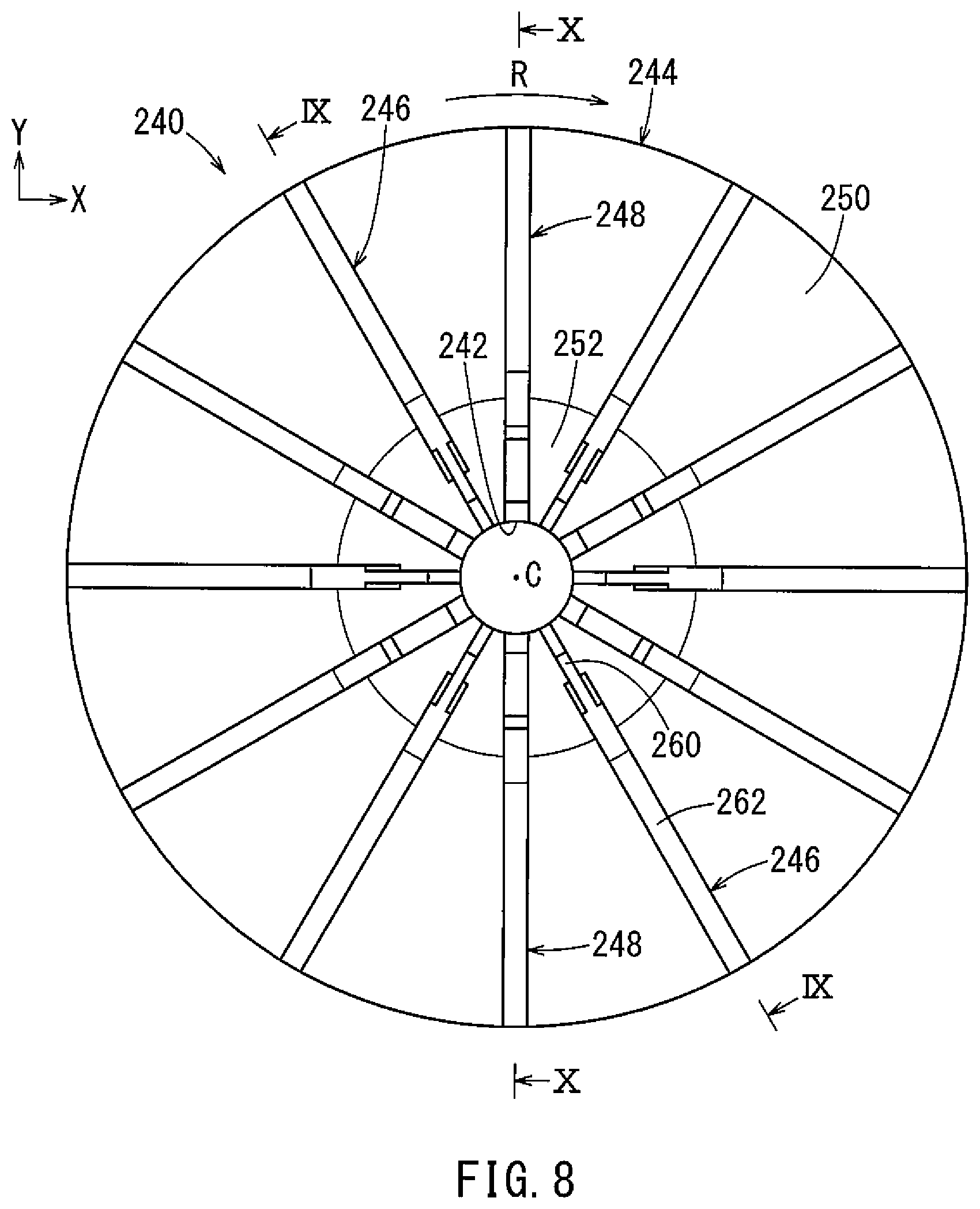
[0015] FIG. 8 is a plan view of the impeller of FIG. 7.
[0016] FIG. 9 is a cross-sectional view of the impeller of FIG. 8 taken along line IX-IX in FIG. 8.
[0017] FIG. 10 is a cross-sectional view of the impeller of FIG. 8 taken along line X-X in FIG. 8.
[0018] FIG. 11 is a perspective view of a fourth embodiment of an impeller in accordance with the principles described herein.
[0019] FIG. 12 is a plan view of the impeller of FIG. 11.
[0020] FIG. 13 is a cross-sectional view of the impeller of FIG. 12 taken along line in FIG. 12.
[0021] FIG. 14 is a cross-sectional view of the impeller of FIG. 12 taken along line XIV-XIV in FIG. 12.
[0022] FIG. 15 is a side view of a second blade of the impeller of FIG. 12 viewed along line XV in FIG. 12.
[0023] FIG. 16 is a side view of a first blade of the impeller of FIG. 12 viewed along line XVI in FIG. 12.
DETAILED DESCRIPTION
[0024] In general, the shape of the blades of a centrifugal pump affects the pumping efficiency. Consequently, various types of blades have been provided for the purpose of improving the pump efficiencies of centrifugal pumps. For example, in Japanese Laid-Open Patent Publication No. H11-218097, an impeller includes a plurality of first blades and a plurality of second blades that are shorter than the first blades. The first blades extend radially from a central portion of the impeller to a radially outer periphery of the impeller. The second blades extend radially from a region spaced from the central portion of the impeller to a position proximal the radially outer periphery of the impeller. In such centrifugal pumps, the second blades do not extend to or proximal the central portion of the impeller. As a result, an opening is defined between the radially inner ends of each pair of circumferentially adjacent first blades. The area of each such opening can be increased to improve the pump efficiency. However, because the second blades are shorter than the first blades, the volume of a fluid forced by each second blade is generally less than the volume of the fluid forced by each first blade. Therefore, there has been a need for an improved centrifugal pump.
[0025] A centrifugal pump generally includes an impeller and a housing forming a pump chamber for housing the impeller therein. The impeller has a main plate with a substantially circular shape and a plurality of blades extending radially along a top surface of the main plate from proximal a center of the impeller to a radially outer periphery of the impeller. When the centrifugal pump is operated, the impeller is rotated about a rotational axis such in a rotational direction such that a fluid is forced forward by the blades of the impeller relative to the rotational direction in the pump chamber so as to flow radially outward. As a result, the centrifugal pump suctions the fluid into the pump chamber and discharges the fluid from the pump chamber.
[0026] One conventional method for improving the pump efficiency of a centrifugal pump is to increase the number of blades. However, when too many conventional blades are provided on the main plate of the impeller, a space near the central portion of the impeller is crowded with radially inner ends of the blades. Thus, an area of each opening, through which the fluid flows from a space just above the central portion of the impeller into spaces between the blades, is relatively small. In such state, the flow of fluid from the space just above the central portion of the impeller into the spaces between the blades is limited, so that the pump efficiency cannot be improved effectively. Each opening is defined by the radially inner ends of each pair of circumferentially adjacent blades and the top surface of the main plate near the center of the impeller. In this disclosure, the area of the opening may also be referred to as "opening area."
[0027] To improve the pump efficiency of the centrifugal pump, embodiments described herein are directed to impellers having two kinds of blades for simultaneously increasing both the opening area and the number of the blades on the main plate. More specifically, as shown in FIG. 6, the impeller includes a plurality of long blades and a plurality of short blades. The long blades are longer than the short blades in a plan view of the impeller. The long blades and the short blades extend radially inward from the outer circumferential periphery of the impeller and are alternately arranged in a circumferential direction of the impeller. A radial distance between the central, rotational axis of the impeller and a radially inner end of each long blade is less than a radial distance between the central, rotational axis of the impeller and a radially inner end of each short blade in the plan view of the impeller. In this case, the radially inner ends of the short blades do not extend radially to a central portion of the impeller, so that each opening at the central portion of the impeller is defined by the radially inner ends of each pair of circumferentially adjacent long blades. Thus, the opening area of each opening can be increased in comparison with a conventional impeller with the same total number of blades, but with each blade extending radially from or proximal the central portion of the impeller to the outer periphery of the impeller.
[0028] As described above, regarding the example of the impeller shown in FIG. 6, the radial distance between the rotational axis and the radially inner end of each short blade is greater than the radial distance between the rotational axis and the radially inner end of each long blade. Thus, in a space within a predetermined radial distance from the rotational axis of the impeller in the plan view, the fluid is forced by the long blades only, and is not forced by the short blades. Accordingly, the amount of the fluid forced by the long blades is significantly greater than that of the short blades. Therefore, there has been a need for an improved centrifugal pump.
[0029] The following discussion is directed to various exemplary embodiments. However, one skilled in the art will understand that the examples disclosed herein have broad application, and that the discussion of any embodiment is meant only to be exemplary of that embodiment, and not intended to suggest that the scope of the disclosure, including the claims, is limited to that embodiment.
[0030] A first embodiment will be described with reference to FIGS. 1 to 5. In the first embodiment, a centrifugal pump 10 is used as a purge pump mounted on a vehicle, such as an automobile, for supplying a deficiency of a purge flow from a canister to an intake passage of an internal combustion engine. In each drawing, X direction shows the rightward direction, Y direction shows the forward direction, and Z direction shows the upward direction, such that X direction, Y direction, and Z direction are perpendicular to each other. However, these directions do not limit the orientation or the mounting direction of the centrifugal pump 10 on the vehicle.
[0031] As shown in FIG. 1, the centrifugal pump 10 includes a motor 12, an impeller 140 configured to be rotated by the motor 12, and a housing 16 that houses both the motor 12 and the impeller 140 therein. The motor 12 may be a brushless motor. The motor 12 includes a rotor 18, a shaft 20, and a stator 22. The rotor 18 has a hollow cylindrical shape. The shaft 20 has a lower end that is coaxially inserted into the rotor 18. The stator 22 surrounds an outer circumference of the rotor 18. The rotor 18 includes a plurality of permanent magnets, such that the rotor 18 shows magnetic poles aligned in a circumferential direction relative to a central axis of the shaft 20. The stator 22 includes a plurality of coils surrounding the outer circumference of the rotor 18 by a predetermined distance.
[0032] The shaft 20 has an upper end coaxially inserted into a central hole 142 of the impeller 140, such that the shaft 20 is configured to transmit torque, generated between the rotor 18 and the stator 22, to the impeller 140. The housing 16 includes a first housing part 24 and a second housing part 26. Each of the first housing part 24 and the second housing part 26 may be made from a resin material. The first housing part 24 and the second housing part 26 are coupled to each other to define a pump chamber 28. The impeller 140 is housed in the pump chamber 28, such that the impeller 140 can rotate in the pump chamber 28 without coming into contact with an inward facing surface of the housing 16. The first housing part 24 has a suction part 30 having a hollow cylindrical shape extending upward. The suction part 30 defines a suction passage 32 therein. The suction part 30 includes an inlet port 34 at an upstream end of the suction passage 32, i.e. at an opposite end to the pump chamber 28. The suction passage 32 provides fluid communication between the pump chamber 28 and the exterior of the centrifugal pump 10 via the inlet port 34. The first housing part 24 has a discharge part 36 extending in a tangential direction from an outer periphery of the impeller 140 (rightward in FIG. 1). The discharge part 36 defines a discharge passage 38 therein. The discharge part 36 includes an outlet port 40 at a downstream end of the discharge passage 38, i.e. at an opposite end to the pump chamber 28. The discharge passage 38 provides fluid communication between the pump chamber 28 and the exterior of the centrifugal pump 10 via the outlet port 40.
[0033] The centrifugal pump 10 includes bearings 42, 44. Each of the bearings 42, 44 is composed of a ball bearing having both an outer ring and an inner ring, such that the outer ring is fixedly inserted into the second housing part 26 by press-fitting and that the inner ring is fixed on the shaft 20. Due to this configuration, the bearings 42, 44 support the shaft 20 while allowing the shaft 20 to rotate.
[0034] The second housing part 26 houses a control unit 46 at a lower end part thereof. The control unit 46 is coupled to a connector configured to be connected to an external power source, such as a battery mounted on the vehicle. The control unit 46 is configured to receive electric power from the external power source and to supply it to the stator 22.
[0035] Next, the impeller 140 will be described in detail. As shown in FIG. 3, the impeller 140 is configured to rotate about a central, rotational axis C in a rotational direction R that is clockwise in a plan view of the impeller 140. As shown in FIGS. 1 to 3, the impeller 140 includes a main plate 144 having a substantially circular shape, a plurality of first blades 146 extending from the main plate 144, and a plurality of second blades 148 extending from the main plate 144. The main plate 144 has a top surface facing the suction passage 32. The first blades 146 and the second blades 148 are formed on the top surface of the main plate 144. As shown in FIGS. 2 to 5, the main plate 144 has a projection part 152 protruding upward at a central portion thereof and a flat part 150 extending radially outward from an outer periphery of the projection part 152, such that the outer periphery of the projection part 152 is contiguous with a radially inner periphery of the flat part 150. The flat part 150 is oriented perpendicular to the rotational axis C of the impeller 140. As shown in FIGS. 4 and 5, the projection part 152 has an inclined surface 154 continuously increasing the height thereof moving radially inward from the flat part 150.
[0036] The first blades 146 and the second blades 148 extend radially along the top surface of the impeller 140 on both the projection part 152 and the flat part 150. As shown in FIG. 3, in the plan view along the rotational axis C of the impeller 140, each of the first blades 146 has substantially the same shape and the same radial length as each of the second blades 148. In this disclosure, a radial length of a blade is the length of the blade in a radial direction and may be calculated by subtracting the radius of the central hole 142 from the radial distance between the rotational axis C and the radially outer end of the blade in the plan view. The first blades 146 and the second blades 148 are alternately arranged at regular intervals in the circumferential direction. The first blades 146 and the second blades 148 protrude perpendicularly upward from the top surface of the main plate 144.
[0037] As shown in FIG. 3, in the plan view of the impeller 140, each of the blades 146, 148 is gently curved, such that the radially inner end thereof is positioned forward of a virtual line passing through the rotational axis C and the radially outer end of the corresponding blade relative to the rotational direction R of the impeller 140.
[0038] The second blades 148 have the same shape as each other, so that one of the second blades 148 will be described for convenience of explanation. As shown in FIG. 5, the second blade 148 has a radially inner low blade part 156 and a radially outer high blade part 158. The low blade part 156 is positioned proximal the central hole 142 of the main plate 144. Regarding the height from the main plate 144, the low blade part 156 of the second blade 148 is less than the first blades 146 when comparing them to each other at any given radial distance from the rotational axis C. The high blade part 158 is positioned radially outward of the low blade part 156. Regarding the height from the main plate 144, the high blade part 158 of the second blade 148 is equal to the first blades 146 at any given radial distance from the rotational axis C. In this embodiment, the low blade part 156 is formed on the projection part 152 only, whereas the high blade part 158 extends along both the projection part 152 and the flat part 150. Thus, as shown in FIG. 5, a boundary, which is identified with a boundary line B, between the low blade part 156 and the high blade part 158 is positioned just above the projection part 152. The height of the low blade part 156 continuously increases moving radially toward the boundary line B. In this disclosure, the height of each blade from the main plate is the distance measured from the main plate to an upper end point of the blade in a direction along a virtual line, passing the upper end point and being normal to the top surface of the main plate, in a cross-sectional view of the blade along a plane parallel to the rotational axis C.
[0039] Next, an operation of the centrifugal pump 10 will be described with reference to FIG. 1. When the control unit 46 supplies electric power to the stator 22, the stator 22 produces a magnetic field. The rotor 18 is rotated by the magnetic field, such that the shaft 20, the inner rings of the bearings 42, 44, and the impeller 140 are integrally rotated with the rotor 18 about rotational axis C in rotational direction R. Due to rotation of the impeller 140, a fluid, i.e. purge gas is suctioned into the suction passage 32 via the inlet port 34 in a suction direction Y1 and flows through the suction passage 32 toward the central portion of the impeller 140. Then, the fluid is forced by the first blades 146 and the second blades 148 in the rotational direction R of the impeller 140 while flowing radially outward along the top surface of the main plate 144. As a result, the fluid is pressurized and is discharged from the outlet port 40 via the discharge passage 38 in a discharge direction Y2.
[0040] In accordance with the first embodiment, regarding the height from the main plate 144, the low blade part 156 of each second blade 148 is less than each first blade 146 when comparing the first blades 146 and the second blades 148 to each other at an equal distance from the rotational axis C. Thus, an opening area of each opening of the impeller 140 can be increased in comparison with a case where the height of each second blade 148 is the same as that of each first blade 146 over the entire radial length thereof. Further, in a space near the central portion of the impeller 140, most of the fluid flows radially outward due to inclination of the inclined surface 154, so that the amount of the fluid moved by the low blade part 156 of each second blade 148 is substantially the same as, and in particular, slightly less than the amount of the fluid moved by each first blade 146. Thus, the amount of the fluid forced by the second blades 148 can be increased, thereby decreasing a difference between the amount of the fluid forced by the first blades 146 and the amount of the fluid forced by the second blades 148. Such difference may cause pulsations in the fluid flow. Accordingly, the pump efficiency of the centrifugal pump 10 can be improved, while preventing the pulsations in the fluid flow.
[0041] The height of the low blade part 156 of each second blade 148 from the main plate 144 continuously increases moving radially outward from the radially inner end to the radially outer end thereof. Due to this configuration, the impeller 140 can be easily produced by using molds.
[0042] The main plate 144 includes the projection part 152 and the flat part 150 extending radially outward from the projection part 152. In a radially inner space positioned above the projection part 152, the fluid is not pressurized sufficiently by the first blades 146 and the second blades 148, and thus, the fluid flows along the inclined surface 154. In a radially outer space positioned above the flat part 150, the fluid is forced and sufficiently pressurized by the first blades 146 and the second blades 148 to be moved forward relative to the rotational direction R and radially outward. Accordingly, each second blade 148, having the low blade part 156 on the projection part 152 and the high blade part 158 extending over the entire radial length of the flat part 150, can sufficiently force the fluid to flow above the flat part 150.
[0043] The first blades 146 and the second blades 148 are alternately arranged at regular intervals in the circumferential direction of the impeller 140. Thus, the opening area of each opening of the impeller 140 can be held substantially constant in the circumferential direction of the impeller 140. Further, the difference between the amounts of the fluid forced by each of the first blades 146 and the second blades 148 can be decreased.
[0044] A second embodiment will be described with reference to FIGS. 7 to 10. The second embodiment is substantially the same as the first embodiment described above, with some differences regarding the shape of an impeller 240. Thus, while the differences will be described, similar configurations will be described shortly or will not be described in the interest of conciseness.
[0045] As shown in FIG. 7, the impeller 240 includes a main plate 244 having a substantially circular shape, a plurality of first blades 246 extending along the main plate 244, and a plurality of second blades 248 extending along the main plate 244. The main plate 244 has a central hole 242 at a central portion thereof and a top surface facing upward. The first blades 246 and the second blades 248 are formed on the top surface of the impeller 240. The main plate 244 has a projection part 252 protruding upward at a central portion of the main plate 244, and a flat part 250 extending radially outward from a radially outer periphery of the projection part 252. As shown in FIGS. 9 and 10, the projection part 252 has an inclined surface 254 that continuously increasing in axial height moving radially inward.
[0046] As shown in FIG. 7, the first blades 246 and the second blades 248 extend radially along the projection part 252 and the flat part 250. More specifically, each of the first blades 246 and the second blades 248 extends radially from a radially inner periphery of the inclined surface 254 of the projection part 252 to a radially outer periphery of the flat part 250. The radial length of each first blade 246 is equal to that of each second blade 248. The first blades 246 and the second blades 248 are alternately arranged on the main plate 244 at regular intervals in the circumferential direction of the impeller 240. The first blades 246 and the second blades 248 are oriented perpendicular to the main plate 244 (parallel to the rotational axis C).
[0047] As shown in FIG. 8, in a plan view along the rotational axis C of the impeller 240, each of the first blades 246 and the second blades 248 is positioned along a virtual line extending radially through the rotational axis C. Thus, an inlet angle of each of the first blades 246 and the second blades 248 is 90 degrees. An outlet angle of each of the first blades 246 and the second blades 248 is also 90 degrees.
[0048] The first blades 246 have the same shape as each other, so that one of the first blades 246 will be described in the interest of conciseness. The second blades 248 also have the same shape as each other, so that one of the second blades 248 will be described for convenience of explanation. As shown in FIG. 8, the first blade 246 has a radially inner thin blade part 260 and a radially outer thick blade part 262. The thin blade part 260 extends radially outward from a radially inner periphery of the projection part 252. The thin blade part 260 of the first blade 246 is thinner than the second blade 248 when comparing them to each other at an equal distance from the rotational axis C. The thick blade part 262 extends radially outward from a radially outer end of the thin blade part 260. The thickness of the thick blade part 262 is equal to that of the second blade 248 when comparing them to each other at an equal distance from the rotational axis C. The thin blade part 260 is formed on the projection part 252 of the main plate 244 only, whereas the thick blade part 262 is formed on both the projection part 252 and the flat part 250. Thus, a boundary between the thin blade part 260 and the thick blade part 262 is positioned just above the projection part 252. As shown in FIG. 8, the thickness of the second blade 248 is constant over the whole radial length thereof. The thickness of the second blade 248 may be 1 mm. The thickness of the thin blade part 260 of the first blade 246 is preferably half of the thickness of the thick blade part 262. The thickness of the thin blade part 260 may be 0.5 mm. In this disclosure, the thickness of each blade refers to a dimension of the blade in the front-rear direction relative to the rotational direction R (i.e., the circumferential direction).
[0049] As shown in FIGS. 7 and 10, the second blade 248 has a radially inner low blade part 256 and a radially outer high blade part 258. The low blade part 256 extends radially outward from the radially inner periphery of the inclined surface 254. The high blade part 258 extends radially outward from a radially outer end of the low blade part 256. As shown in FIGS. 9 and 10, the height of the low blade part 256 from the main plate 244 is less than that of the first blade 246 when comparing them to each other at an equal distance from the rotational axis C. The height of the high blade part 258 from the main plate 244 is equal to that of the first blade 246 when comparing them to each other at an equal distance from the rotational axis C. As shown in FIG. 10, the low blade part 256 is formed on the projection part 252 of the main plate 244 only, whereas the high blade part 258 is formed on both the projection part 252 and the flat part 250. Thus, a boundary, which is identified by a boundary line B, between the low blade part 256 and the high blade part 258 is positioned just above the projection part 252. The height of the second blade 248 from the main plate 244 increases at the boundary line B between the low blade part 256 and the high blade part 258 in a stepped manner moving radially outward. More specifically, the height of the second blade 248 from the main plate 244 drastically increases at the boundary line B. The stepped shape may have a projecting part and a recessed part, each forming an angle 85 to 95 degrees in a cross-sectional view of the second blade 248, taken along a plane including both the rotational axis C and a longitudinal axis of the second blade 248.
[0050] In accordance with the second embodiment, the first blades 246 and the second blades 248 have the same radial length as each other. Each of the second blades 248 has the low blade part 256 and the high blade part 258. Each low blade part 256 is formed proximal the central portion of the impeller 240. The height of each low blade part 256 from the main plate 244 is less than that of each first blade 246 when comparing the first blades 246 and the second blades 248 to each other at an equal distance from the rotational axis C. Each high blade part 258 extends radially outward from the radially outer end of the corresponding low blade part 256. The height of each high blade part 258 from the main plate 244 is equal to that of each first blade 246 when comparing them to each other at an equal distance from the rotational axis C. Due to this configuration, the difference between the amount of the fluid forced by the first blades 246 and the amount of the fluid forced by the second blades 248 can be reduced, while increasing an opening area of each opening of the impeller 240. Accordingly, the pump efficiency of the centrifugal pump 10 can be improved.
[0051] The height of each second blade 248 from the main plate 244 increases at the boundary line B between the low blade part 256 and the high blade part 258 in the stepped manner. Thus, the height of each low blade part 256 can be sufficiently lowered over the whole radial length thereof.
[0052] Each second blade 248 includes the low blade part 256 formed on the projection part 252 only and the high blade part 258 extending radially over the whole radial length of the flat part 250. Thus, each second blade 248 has a sufficient height to pressurize and force the fluid to flow radially outward on the flat part 250.
[0053] Each first blade 246 has the thin blade part 260 and the thick blade part 262. The thin blade part 260 of each first blade 246 is thinner than each second blade 248 when comparing them to each other at an equal distance from the rotational axis C. The thickness of each thick blade part 262 is equal to that of each second blade 248 when comparing them to each other at an equal distance from the rotational axis C. Thus, the opening area of each opening of the impeller 240 can be increased in comparison with a case where each first blade 246 has the thickness same as the thick blade part 262 over the whole radial length thereof.
[0054] Each first blade 246 has the thin blade part 260 and the thick blade part 262, which extends radially outward from the radial outer end of the thin blade part 260 and is thicker than the thin blade part 260. Thus, the strength of each first blade 246 can be increased in comparison with a case where each first blade 246 has the thickness same as the thin blade part 260 over the whole radial length thereof.
[0055] The first blades 246 and the second blades 248 are alternately arranged in the circumferential direction of the impeller 240. Thus, the opening area of each opening of the impeller 240 can be held to be substantially constant in the circumferential direction of the impeller 240. Further, the difference between the amounts of the fluid forced by each of the first blades 246 and the second blades 248 can be decreased.
[0056] A third embodiment will be described with reference to FIGS. 11 to 16. The third embodiment is substantially the same as the first embodiment described above, with some differences regarding the shape of an impeller 340. Thus, while the differences will be described, similar configurations will be described shortly or will not be described in the interest of conciseness.
[0057] As shown in FIGS. 11 and 12, the impeller 340 is configured to be rotated about a central, rotational axis C in the rotational direction R that is clockwise direction in a plan view along the rotational axis C of the impeller 340. The impeller 340 includes a main plate 344 having a substantially circular shape, a plurality of first blades 346 extending along the main plate 344, and a plurality of second blades 348 extending along the main plate 344. The main plate 344 has a central hole 342 at a central portion thereof and a top surface facing upward. The first blades 346 and the second blades 348 are formed on the top surface of the main plate 344. The main plate 344 has a projection part 352 protruding upward and a flat part 350 extending radially outward from a radially outer periphery of the projection part 352. The projection part 352 has an inclined surface 354 that continuously increases in axial height moving radially inward.
[0058] Each of the first blades 346 and the second blades 348 extends radially from a radially inner periphery of the inclined surface 354 of the projection part 352 to a radially outer periphery of the flat part 350. As shown in FIG. 12, in the plan view along the rotational axis C of the impeller 340, the radial length of each first blade 346 is equal to that of each second blade 348. The first blades 346 and the second blades 348 are alternately arranged at regular intervals in the circumferential direction of the impeller 340.
[0059] The first blades 346 have the same shape as each other, and the second blades 348 also have the same shape as each other. Thus, one of the first blades 346 and one of the second blades 348 will be described below in the interest of conciseness. Regarding each of the first blade 346 and the second blade 348, in the plan view along the rotational axis C, a radially inner end thereof is positioned, relative to the rotational direction R, in front of a virtual line extending radially from the rotational axis C to a radially outer end thereof. In the plan view, an upper edge of each of the first blades 346 and the second blades 348 is gently curved rearward relative to the rotational direction R moving radially outward.
[0060] As shown in FIGS. 11 and 12, the first blade 346 is divided into a first inner blade part 364 and a first outer blade part 366. The first inner blade part 364 extends radially outward from the radially inner periphery of the inclined surface 354. The first outer blade part 366 extends radially outward from a radially outer end of the first inner blade part 364 to the radially outer periphery of the impeller 340.
[0061] As shown in FIG. 12, in the plan view along the rotational axis of the impeller 340, the first inner blade part 364 is positioned, relative to the rotational direction R, in front of a radial reference line N1, extending radially and passing through the rotational axis C and a connection part between the first inner blade part 364 and the first outer blade part 366. The connection part between the first inner blade part 364 and the first outer blade part 366 corresponds to a radially inner end of the first outer blade part 366. The first outer blade part 366 has a front surface 366F facing forward and a rear surface 366R facing rearward relative to the rotational direction R. In some embodiments, the radial reference line N1 may pass the front surface 366F of the first outer blade part 366 at the radially inner end of the first outer blade part 366.
[0062] As shown in FIG. 11, the first inner blade part 364 has a front surface 364F facing forward and a rear surface 364R facing rearward relative to the rotational direction R The front surface 364F and the rear surface 364R extend perpendicular to the top surface of the main plate 344. In some embodiment, an angle formed between the top surface of the main plate 344 and each of the front surface 364F and the rear surface 364R may be between 85 to 95 degrees.
[0063] The front surface 366F of the first outer blade part 366 extends from the top surface of the main plate 344 obliquely rearward relative to the rotational direction R of the impeller 340. The front surface 366F is contiguous with the front surface 364F of the first inner blade part 364. As shown in FIGS. 13 and 14, the front surface 366F extends linearly between an upper end and a lower end thereof in a cross-sectional view perpendicular to a longitudinal axis of the first outer blade part 366. The front surface 366F may be gently curved in a concave or convex manner in some embodiments.
[0064] In a cross-sectional view perpendicular to the longitudinal axis of the first outer blade part 366, an angle .theta. formed between the front surface 366F of the first outer blade part 366 and a first vertical reference line L, which extends parallel to the rotational axis C and passes through the upper end of the front surface 366F, is acute and continuously increases moving radially outward.
[0065] As shown in FIG. 12, in the plan view along the rotational axis C of the impeller 340, a lower portion of the front surface 366F of a radially outer end of the first outer blade part 366 is positioned in front of the radial reference line N1 relative to the rotational direction R. And, an upper portion of the front surface 366F of the radially outer end of the first outer blade part 366 is positioned rearward of the radial reference line N1 relative to the rotational direction R. This configuration is illustrated in FIGS. 13 and 14 more clearly. In FIGS. 13 and 14, the lower portion of the front surface 366F is positioned, relative to the rotational direction R, in front of a second vertical reference line N1', which extends vertically and perpendicular to the radial reference line N1. The upper portion of the front surface 366F is positioned rearward of the second vertical reference line N1' relative to the rotational direction R. As shown in FIG. 11, a radially outer surface of the first outer blade part 366 is flush with the radially outer periphery of the main plate 344.
[0066] As shown in FIGS. 13 and 14, the thickness T of the first outer blade part 366 in a front-rear direction relative to the rotational direction R (i.e., circumferential direction) continuously increases from an upper end toward a lower end thereof. A rear surface 366R of the first outer blade part 366 extends perpendicular to the top surface of the main plate 344. As shown in FIG. 11, the rear surface 366R of the first outer blade part 366 is contiguous with the rear surface 364R of the first inner blade part 364. The thickness of the first inner blade part 364 in the front-rear direction relative to the rotational direction R is constant between an upper end and a lower end thereof.
[0067] As shown in FIG. 12, the second blade 348 is divided into a second inner blade part 368 and a second outer blade part 370. The second inner blade part 368 extends radially outward from the radially inner periphery of the projection part 352. The second outer blade part 370 extends radially outward from a radially outer end of the second inner blade part 368 to the radially outer periphery of the main plate 344.
[0068] In the plan view along the rotational axis of the impeller 340, the second inner blade part 368 is positioned, relative to the rotational direction R, in front of a radial reference line N2, which extends radially and passes through the rotational axis C and a connection part between the second inner blade part 368 and the second outer blade part 370. The connection part between the second inner blade part 368 and the second outer blade part 370 corresponds to a radially inner end of the second outer blade part 370. As shown in FIG. 11, the second outer blade part 370 has a front surface 370F facing forward and a rear surface 370R facing rearward relative to the rotational direction R. The radial reference line N2 may pass the front surface 370F of the second outer blade part 370 at the radially inner end of the second outer blade part 370 in some embodiments.
[0069] As shown in FIG. 11, the second inner blade part 368 has a front surface 368F facing forward and a rear surface 368R facing rearward relative to the rotational direction R. The front surface 368F and the rear surface 368F extend perpendicular to the top surface of the main plate 344. An angle formed between the top surface of the main plate 344 and each of the front surface 368F and the rear surface 368R may be between 85 to 95 degrees in some embodiments.
[0070] The front surface 370F of the second outer blade part 370 extends from the top surface of the main plate 344 obliquely rearward relative to the rotational direction R of the impeller 340. The front surface 370F is contiguous with the front surface 368F of the second inner blade part 368. The front surface 370F extends linearly between an upper end and a lower end thereof in a cross-sectional view perpendicular to a longitudinal axis of the second outer blade part 370. The front surface 370F may be gently curved in a concave or convex manner in some embodiments.
[0071] Although not illustrated, in a cross-sectional view perpendicular to the longitudinal axis of the second outer blade part 370, an angle formed between the front surface 370F of the second outer blade part 370 and a vertical reference line, which extends parallel to the rotational axis C and passes the upper end of the front surface 370F, is acute and continuously increases from the radially inside toward the radially outside.
[0072] As shown in FIG. 12, in the plan view along the rotational axis C of the impeller 340, a lower portion of the front surface 370F of a radially outer end of the second outer blade part 370 is positioned in front of the radial reference line N2 relative to the rotational direction R. An upper portion of the front surface 370F of the radially outer end of the second outer blade part 370 is positioned rearward of the radial reference line N2 relative to the rotational direction R. As shown in FIG. 11, a radially outer surface of the second outer blade part 370 is flush with the radially outer periphery of the main plate 344.
[0073] As shown in FIG. 11, the thickness of the second outer blade part 370 in the front-rear direction relative to the rotational direction R (i.e., circumferential direction) gradually increases from an upper end toward a lower end thereof. A rear surface 370R of the second outer blade part 370 extends perpendicular to the top surface of the main plate 344 in a cross-sectional view perpendicular to the longitudinal axis of the second blade 348. The rear surface 370R of the second outer blade part 370 is contiguous with the rear surface 368R of the second inner blade part 368. The thickness of the second inner blade part 368 in the front-rear direction relative to the rotational direction R (i.e., circumferential direction) is constant between an upper end and a lower end thereof.
[0074] As shown in FIGS. 11 and 15, the second blade 348 has a low blade part 356 and a high blade part 358. The low blade part 356 extends radially outward from the radially inner periphery of the inclined surface 354. The high blade part 358 extends radially outward from a radially outer end of the low blade part 356. As shown in FIGS. 11, 15 and 16, the height of the low blade part 356 of the second blade 348 from the main plate 344 is less than that of the first blade 346 when comparing them to each other at an equal distance from the rotational axis C. The height of the high blade part 358 from the main plate 344 is equal to that of the first blade 346 when comparing them to each other at an equal distance from the rotational axis C. The low blade part 356 is formed on the projection part 352 of the main plate 344 only, whereas the high blade part 358 extends on both the projection part 352 and the flat part 350. Thus, a boundary between the low blade part 356 and the high blade part 358, which is near a boundary line B in FIG. 15, is positioned just above the projection part 352. The height of the low blade part 356 continuously increases moving radially from the inner end of the low blade part 356 toward the boundary line B between the low blade part 356 and the high blade part 358.
[0075] In accordance with the third embodiment, the first blades 346 and the second blades 348 have the same radial length as each other. Each second blade 348 has the low blade part 356 and the high blade part 358. Each low blade part 356 is formed near the central portion of the impeller 340. The height of each low blade part 356 from the main plate 344 is less than that of each first blade 346 when comparing them to each other at an equal distance from the rotational axis C. Each high blade part 358 extends radially outward from the radially outer end of the corresponding low blade part 356. The height of each high blade part 358 from the main plate 344 is equal to that of each first blade 346 when comparing them to each other at an equal distance from the rotational axis C. Due to this configuration, the difference between the amount of the fluid forced by the first blades 346 and the amount of the fluid forced by the second blades 348 can be reduced, while increasing the opening area of each opening of the impeller 340. Accordingly, the pump efficiency of the centrifugal pump 10 can be improved.
[0076] The height of the low blade part 356 of each second blade part 348 from the main plate 344 continuously increases moving radially outward. Thus, the impeller 340 can be easily produced by using molds.
[0077] The low blade part 356 of each second blade 348 is formed on the projection part 352 only, whereas the high blade part 356 of each second blade 348 extends radially over the whole radial length of the flat part 350. Thus, each second blade 348 has a sufficient height to pressurize and force the fluid to flow radially outward on the flat part 350.
[0078] The first blades 346 and the second blades 348 are alternately arranged in the circumferential direction of the impeller 340. Thus, the opening area of each opening of the impeller 340 can be held to be substantially constant in the circumferential direction of the impeller 340. Further, the difference between the amounts of the fluid forced by each of the first blades 346 and the second blades 348 can be decreased.
[0079] As mentioned above, the apparatuses and methods disclosed herein are not limited to the above-described embodiments. For example, the centrifugal pump may be used for pumping various fluids, such as air, water, or the like. The motor may be composed of a brushed motor. The main plate may have additional blades or grooves along a lower surface thereof. The projection part may be omitted, such that the main plate may have a flat top surface having a circular shape. The height of the low blade part may increase toward the radially inside.
[0080] The thickness of the thin blade part of each second blade may gradually increase toward the radial outside. Each second blade may have a thin blade part and a thick blade part instead of the first blades.
[0081] The impeller may include a plurality of third blades each having a low blade part and a high blade part. In such case, the height of the low blade part of each third blade from the main plate is lower or higher than that of each second blade when comparing them to each other at an equal distance from the rotational axis of the impeller.
[0082] The numbers of the first blades, the second blades, and the third blades may be different from each other. However, the first blades, the second blades, and the third blades are preferably arranged on the main plate in the circumferential direction on the basis of a repetitive order pattern.
[0083] The blades may not be arranged at regular intervals in the circumferential direction. However, the blades are preferably positioned on the main plate on the basis of a predetermined regularity. For example, in a case where the impeller includes first blades, second blades, and third blades repeatedly, a first predetermined circumferential distance between the first blade and the second blade may be greater than a second predetermined circumferential distance between the second blade and the third blade in each repeating unit.
* * * * *
D00000
D00001
D00002
D00003
D00004
D00005
D00006
D00007
D00008
D00009
D00010
D00011
XML
uspto.report is an independent third-party trademark research tool that is not affiliated, endorsed, or sponsored by the United States Patent and Trademark Office (USPTO) or any other governmental organization. The information provided by uspto.report is based on publicly available data at the time of writing and is intended for informational purposes only.
While we strive to provide accurate and up-to-date information, we do not guarantee the accuracy, completeness, reliability, or suitability of the information displayed on this site. The use of this site is at your own risk. Any reliance you place on such information is therefore strictly at your own risk.
All official trademark data, including owner information, should be verified by visiting the official USPTO website at www.uspto.gov. This site is not intended to replace professional legal advice and should not be used as a substitute for consulting with a legal professional who is knowledgeable about trademark law.