Exhaust System For An Internal Combustion Engine Of A Motor Vehicle As Well As Motor Vehicle
Chen; Lin Strobio
U.S. patent application number 16/812675 was filed with the patent office on 2020-09-17 for exhaust system for an internal combustion engine of a motor vehicle as well as motor vehicle. The applicant listed for this patent is Faurecia Emissions Control Technologies, Germany GmbH. Invention is credited to Lin Strobio Chen.
| Application Number | 20200291837 16/812675 |
| Document ID | / |
| Family ID | 1000004719170 |
| Filed Date | 2020-09-17 |


| United States Patent Application | 20200291837 |
| Kind Code | A1 |
| Chen; Lin Strobio | September 17, 2020 |
EXHAUST SYSTEM FOR AN INTERNAL COMBUSTION ENGINE OF A MOTOR VEHICLE AS WELL AS MOTOR VEHICLE
Abstract
An exhaust system for an internal combustion engine of a motor vehicle includes an exhaust-gas line and an associated active silencing device. A sound coupling-in line of the silencing device substantially concentrically surrounds the exhaust-gas line on the outside. A first perforation is provided in an axial portion facing away from a sound line in an area of the exhaust-gas line enclosed by the sound coupling-in line. An axial portion facing the sound line is designed perforation-free at least in a portion. Furthermore, a motor vehicle with such an exhaust system is explained.
| Inventors: | Chen; Lin Strobio; (Augsburg, DE) | ||||||||||
| Applicant: |
|
||||||||||
|---|---|---|---|---|---|---|---|---|---|---|---|
| Family ID: | 1000004719170 | ||||||||||
| Appl. No.: | 16/812675 | ||||||||||
| Filed: | March 9, 2020 |
| Current U.S. Class: | 1/1 |
| Current CPC Class: | F01N 1/065 20130101; F01N 2470/02 20130101 |
| International Class: | F01N 1/06 20060101 F01N001/06 |
Foreign Application Data
| Date | Code | Application Number |
|---|---|---|
| Mar 11, 2019 | DE | 10 2019 106 159.8 |
Claims
1. An exhaust system for an internal combustion engine of a motor vehicle comprising: an exhaust-gas line routing exhaust gas; an active silencing device that comprises a sound-generating unit which is acoustically coupled to the exhaust-gas line via a sound line and a sound coupling-in line connected downstream thereto, such that sound generated by the sound-generating unit can be introduced into an exhaust gas flow present inside the exhaust-gas line; wherein the sound coupling-in line substantially concentrically surrounds the exhaust-gas line on an outside and an area of the exhaust-gas line enclosed by the sound coupling-in line has an axial portion facing the sound line and an axial portion connected downstream thereto facing away from the sound line; and wherein a first perforation is provided in the axial portion facing away from the sound line and the axial portion facing the sound line is designed perforation-free at least in a portion.
2. The exhaust system of claim 1 wherein the first perforation runs around a whole periphery of the axial portion of the exhaust-gas line facing away from the sound line.
3. The exhaust system of claim 1 wherein openings comprised by the first perforation each have a substantially round cross section.
4. The exhaust system of claim 1 wherein, in the area enclosed by the sound coupling-in line upstream of the first perforation, the exhaust-gas line has a second perforation in a peripheral portion facing away from the sound line, wherein a peripheral portion facing the sound line is designed perforation-free.
5. The exhaust system of claim 4 wherein at least one radial rib is provided on an outer surface of the exhaust-gas line between the peripheral portion facing away from the sound line and the peripheral portion facing the sound line.
6. The exhaust system of claim 4 wherein at least one radial rib is provided on an inner surface of the sound coupling-in line between the peripheral portion facing away from the sound line and the peripheral portion facing the sound line.
7. The exhaust system of claim 5 wherein the at least one radial rib comprises a plurality of ribs with one radial rib being provided in each of two border areas between the peripheral portion facing away from the sound line and the peripheral portion facing the sound line.
8. The exhaust system of claim 5 wherein the at least one radial rib is shorter in an axial direction of the exhaust-gas line than the sound coupling-in line.
9. The exhaust system of claim 4 wherein openings comprised by the second perforation each have a substantially rectangular cross section.
10. The exhaust system of claim 5 wherein a radial outer end of the at least one radial rib or radial ribs provided on the outer surface of the exhaust-gas line is or are at a radial distance from the sound coupling-in line, wherein each radial rib radiating from the exhaust-gas line is complemented by a radial rib, pointing radially inwards radiating from the sound coupling-in line, which is at only a small peripheral distance from an associated radial rib radiating from the exhaust-gas line or touches the periphery of same, and the radial inside end of which is at a radial distance from the exhaust-gas line.
11. The exhaust system of claim 1 wherein, in an area upstream of the sound coupling-in line, the exhaust-gas line has an axial bend or an axial kink.
12. The exhaust system of claim 11 wherein, in the area enclosed by the sound coupling-in line upstream of the first perforation, the exhaust-gas line has a second perforation in a peripheral portion facing away from the sound line, wherein a peripheral portion facing the sound line is designed perforation-free, and wherein the second perforation is arranged downstream of a convex area of the axial bend or of the axial kink.
13. The exhaust system of claim 1 wherein a center axis of the sound line runs substantially along a radial direction of the sound coupling-in line.
14. The exhaust system of claim 5 wherein the at least one radial rib extends up to the sound coupling-in line.
15. The exhaust system of claim 6 wherein the at least one radial rib extends up to the sound coupling-in line.
16. The exhaust system of claim 9 wherein a short side of the rectangle is oriented in a peripheral direction and a long side of the rectangle is oriented in an axial direction of the exhaust-gas line.
17. The exhaust system of claim 11 wherein the axial bend or axial kink is substantially 90.degree..
18. A motor vehicle with an exhaust system of claim 1.
Description
CROSS-REFERENCE TO RELATED APPLICATIONS
[0001] This application is a U.S. non-provisional application claiming the benefit of German Application No. 10 2019 106 159.8, filed on Mar. 11, 2019, which is incorporated herein by its entirety.
TECHNICAL FIELD
[0002] The disclosure relates to an exhaust system for an internal combustion engine of a motor vehicle, with an exhaust-gas line routing exhaust gas and an active silencing device, wherein the active silencing device comprises a sound-generating unit which is acoustically coupled to the exhaust-gas line via a sound line and a sound coupling-in line connected downstream thereto, with the result that sound generated by the sound-generating unit can be introduced into an exhaust gas flow present inside the exhaust-gas line.
[0003] Furthermore, the disclosure relates to a motor vehicle with such an exhaust system.
BACKGROUND
[0004] Such exhaust systems are known from the state of the art. Via the active silencing device, sound can be generated which is superposed with a sound carried by the exhaust gas flow. Here, the superposition is at least partly destructive in nature, with the result that the sound carried by the exhaust gas flow is muffled or cancelled by the active silencing device.
[0005] As a rule, loudspeakers which can function only within a specific temperature range are used as sound-generating units of such silencing devices.
[0006] In exhaust systems, the situation often arises that a temperature of the exhaust gas flow, which carries the sound to be muffled or cancelled, lies outside the temperature window in which loudspeakers or other sound-generating units function reliably. For this reason, such components of active silencing devices must be protected against the high temperatures of the exhaust gas flow. However, thermal protection must not take place at the expense of the acoustic effectiveness of the silencing device. In other words, in exhaust systems with active silencing devices, a compromise between acoustic effectiveness and reliability must always be chosen.
[0007] An exhaust system is to be provided that has an active silencing device, which is acoustically particularly effective and at the same time functions reliably. In particular, the active silencing device is to be reliably protected against the thermal influences of the exhaust gas flow.
SUMMARY
[0008] An exhaust system has a sound coupling-in line that substantially concentrically surrounds an exhaust-gas line on an outside, and an area of the exhaust-gas line enclosed by the sound coupling-in line has an axial portion facing a sound line and an axial portion connected downstream thereto facing away from the sound line. A first perforation is provided in the axial portion facing away from the sound line and the axial portion facing the sound line is designed perforation-free at least in a portion. A sound generated by the sound-generating unit therefore firstly runs through the sound line and thus passes into the sound coupling-in line, to be more precise into an annular space between the sound coupling-in line and the exhaust-gas line. From here, the sound passes into the inside of the exhaust-gas line via the first perforation and can thus interact with the sound carried by the exhaust gas flow. By a perforation is meant in this connection a group of openings which are arranged with a degree of regularity. An axial portion designed perforation-free at least in a portion is here either designed wholly without perforation or has a perforation merely in one portion. Compared with the axial portion facing away from the sound line, the portion facing the sound line is thus less markedly perforated. This can be effected, for example, in that a total cross section of the perforation openings in the axial portion facing the sound line is lower than a total cross section of the perforation openings in the axial portion facing away from the sound line. Because the axial portion facing the sound line is designed perforation-free at least in a portion, i.e. has no openings at least in a portion, a flow, coming from this axial portion, of a possibly hot exhaust gas flow into the sound line is reduced or wholly prevented. Consequently, a flow of hot exhaust gas to the sound-generating unit is thus also reduced or prevented. A flow of hot exhaust gas in the direction of the sound-generating unit can thus substantially only take place via the axial portion facing away from the sound line and the first perforation provided there. The sound-generating unit is thus protected against a direct inflow by a hot exhaust gas flow because such an inflow is wholly or partly prevented. An exhaust gas flow exiting the exhaust-gas line via the first perforation can reach the sound-generating unit only via several deviations. This means that the exhaust gas flow cools significantly on its way to the sound-generating unit. Thus, the sound-generating unit is effectively protected against the temperature influences of the exhaust gas flow. As a result, it functions reliably and is durable. At the same time, the sound-generating unit can be arranged relatively close to the exhaust-gas line, as a result of which the latter can be operated efficiently and effectively from an acoustic point of view. Moreover, an exhaust system designed in this way can be constructed comparatively compact. In other words, it requires only a comparatively small installation space on a motor vehicle which is fitted with such an exhaust system. It can also be flexibly integrated into available installation spaces.
[0009] The idea underlying the disclosure is to perforate that area of the exhaust-gas line which is surrounded by the sound coupling-in line but lies in the region of the sound line as little as possible or not at all. The region of the sound line is to be understood as an axial portion of the exhaust-gas line which lies opposite a mouth of the sound line into the sound coupling-in line. The perforation, which is necessary for the acoustic coupling of the sound-generating unit to the inside of the exhaust-gas line, is arranged as far as possible outside the abovementioned region, thus in an axial portion of the exhaust-gas line facing away from the sound line. Here, the axial portion facing away from the sound line can directly adjoin the portion, facing the sound line, that is perforation-free at least in a portion or be arranged at a particular distance from the portion that is perforation-free at least in a portion.
[0010] Consequently, such an exhaust system is close to ideal in that the sound-generating unit is coupled resistance-free from an acoustic point of view to the inside of the exhaust-gas line, but at the same time exhaust gas cannot flow out of the inside of the exhaust-gas line to the sound-generating unit.
[0011] A further thermal decoupling of the sound-generating device from the exhaust gas flow can be achieved by lengthening the sound line. The geometric distance of the sound-generating unit from the exhaust-gas line is thereby increased.
[0012] The first perforation advantageously runs around the whole periphery of the axial portion of the exhaust-gas line facing away from the sound line. This results in an effective coupling of the sound generated by the sound-generating unit into the inside of the exhaust-gas line.
[0013] The openings comprised by the first perforation preferably each have a substantially round cross section. It has become apparent that such a first perforation is particularly suitable for coupling the active silencing unit to the inside of the exhaust-gas line and at the same time limiting an outflow of exhaust gas via the first perforation.
[0014] In an embodiment, the exhaust-gas line has a second perforation in the area enclosed by the sound coupling-in line upstream of the first perforation in a peripheral portion facing away from the sound line, wherein a peripheral portion facing the sound line is designed perforation-free. The peripheral portion facing away from the sound line and the peripheral portion facing the sound line are preferably complementary to each other to form the whole periphery of the exhaust-gas line, i.e. there are no further peripheral portions. This second perforation serves to acoustically couple the sound-generating unit to the inside of the exhaust-gas line. A sound generated by the sound-generating unit therefore firstly runs through the sound line and thus passes into the sound coupling-in line, to be more precise into an annular space between the sound coupling-in line and the exhaust-gas line. From here, the sound passes into the inside of the exhaust-gas line via the second perforation and can thus interact with the sound carried by the exhaust gas flow. By a perforation is again meant a group of openings which are arranged with a degree of regularity. Because the peripheral portion facing the sound line is designed perforation-free, thus has no openings, a possibly hot exhaust gas flow coming from the inside of the exhaust-gas line is prevented from flowing directly into the sound line and in this way reaching the sound-generating unit. A flow of hot exhaust gas in the direction of the sound-generating unit is instead possible only via the peripheral portion facing away from the sound line and the second perforation provided there. The sound-generating unit is thus protected against a direct inflow by a hot exhaust gas flow. An exhaust gas flow exiting the exhaust-gas line via the second perforation can reach the sound-generating unit only via several deviations. This means that the exhaust gas flow cools significantly on its way to the sound-generating unit. Thus, the sound-generating unit is particularly effectively protected against the temperature influences of the exhaust gas flow. Moreover, an exhaust system designed in this way can be constructed comparatively compact.
[0015] For the case where both a first and a second perforation are provided, it can happen that exhaust gases exit the inside of the exhaust-gas line via the second perforation. They can then be returned into the exhaust-gas line again via the first perforation. This is possible due to the downstream arrangement of the first perforation relative to the second perforation. The static pressure prevailing within the exhaust-gas line namely decreases along the flow direction of the exhaust gas. An exhaust gas flow which has exited the exhaust-gas line via the second perforation at comparatively high pressure can thus re-enter the inside of the exhaust-gas line along the pressure gradient via the first perforation. The pressure ratios are reversed in the gap between the exhaust-gas line and the sound coupling-in line. Here, the highest static pressure is reached at the downstream end of the gap, thus in the area of the first perforation. Because of these pressure ratios, hot exhaust gases are consequently prevented from flowing in the direction of the active silencing unit.
[0016] A radial rib, which preferably extends up to the sound coupling-in line, can be provided on an outer surface of the exhaust-gas line between the peripheral portion facing away from the sound line and the peripheral portion facing the sound line. Such a radial rib represents a flow obstacle for an exhaust gas flow which flows out of the inside of the exhaust-gas line in the direction of the sound-generating unit. Thus, the inflow of hot exhaust gas into the active silencing device is further prevented. In addition, the radial rib can be formed as cooling fin for the exhaust-gas line. Thus, the exhaust gas flow present inside the exhaust-gas line is cooled by via the radial rib.
[0017] The radial rib can either be attached to the exhaust-gas line on the outside and extend in the direction of the sound coupling-in line or be attached to the sound coupling-in line on the inside and extend in the direction of the exhaust-gas line. It is likewise possible for the radial rib to be connected both to the outside of the exhaust-gas line and to the inside of the sound coupling-in line. For example, the radial rib can be welded to the exhaust-gas line and/or the sound coupling-in line. It is likewise possible to manufacture the radial rib integral with the exhaust-gas line and/or the sound coupling-in line.
[0018] According to an embodiment, a radial rib is provided in each of the two border areas between the peripheral portion facing away from the sound line and the peripheral portion facing the sound line. Thus, a total of two radial ribs are provided. They each represent a flow obstacle at the transition point between the peripheral portion facing away from the sound line and the peripheral portion facing the sound line, with the result that, as already described above, the inflow of hot exhaust gas into the sound line is impeded or prevented. The two radial ribs are arranged, for example, radially opposite, thus they are offset relative to each other by an angle of 180.degree. on the periphery of the exhaust-gas line. Naturally, it is also possible to choose a different angle here. Thus, for example, the peripheral portion facing away from the sound line can merely cover an angle of 90.degree. and the peripheral portion facing the sound line can cover an angle of 270.degree.. Intermediate values are also possible. As a result of the second radial rib, the protection of the active silencing unit against hot exhaust gases is particularly effective.
[0019] The radial rib is preferably shorter in axial direction of the exhaust-gas line than the sound coupling-in line. Thus, at an axial end of the annular space formed by the exhaust-gas line and the sound coupling-in line, an acoustic coupling channel results via which sound generated by the sound-generating unit can flow around the radial rib or the radial ribs on the periphery of the exhaust-gas line. Only as it progresses further can the sound pass into the inside of the exhaust-gas line via the second perforation. An effective acoustic coupling of the silencing device to the inside of the exhaust-gas line is thereby guaranteed.
[0020] An exhaust system in which the radial ribs merely extend to an axial length which corresponds to the axial length of the second perforation is particularly preferred. Thus, no radial ribs are provided in the area of the first perforation.
[0021] In a variant, the openings comprised by the second perforation each have a substantially rectangular cross section, wherein preferably a short side of the rectangle is oriented in peripheral direction and a long side of the rectangle is oriented in axial direction of the exhaust-gas line. It has become apparent that a second perforation designed in such a way effects a good compromise between a thermal decoupling of the inside of the exhaust-gas line from the active silencing device and an effective acoustic coupling of these components.
[0022] An alternative design provides that a radial outer end of the radial rib or radial ribs provided on the outer surface of the exhaust-gas line is or are at a radial distance from the sound coupling-in line, wherein each radial rib radiating from the exhaust-gas line is complemented by a radial rib, pointing radially inwards radiating from the sound coupling-in line, which is at only a small peripheral distance from the associated radial rib radiating from the exhaust-gas line or touches the periphery of same, and the radial inside end of which is at a radial distance from the exhaust-gas line. Each radial rib provided on the outer surface of the exhaust-gas line forms a so-called radial rib pair together with the radial rib allocated to it provided on the sound coupling-in line. An alternative term for this is double rib. Such a radial rib pair represents an effective flow obstacle for hot exhaust gases, with the result that the active sound-generating unit is protected against high temperatures. The fact that the radial rib radiating from the outer surface of the exhaust-gas line is not connected to the sound coupling-in line and the radial rib radiating from the sound coupling-in line is not connected to the exhaust-gas line is advantageous in terms of production technology. Namely, the necessity of attaching a radial rib both to the exhaust-gas line and to the sound coupling-in line, which is complex, is avoided. Moreover, the omission of such connections results in a particularly long service life of the exhaust system as the connection points are often exposed to comparatively high stresses.
[0023] The small peripheral distance between the radial ribs forming the radial rib pair is to be seen in comparison with the line diameter of the exhaust-gas line and means that the distance is at most 10%, preferably at most 5%, of the line diameter. In this way, it is achieved that hot exhaust gas, given a flow in the direction of the active silencing device, is effectively countered by a flow resistance.
[0024] In an area upstream of the sound coupling-in line, the exhaust-gas line can have an axial bend or an axial kink, in particular wherein an axial bend of substantially 90.degree. is present. The sound coupling-in line is preferably arranged directly adjacent to the axial bend or the axial kink. A compact construction of the exhaust system thus results. As a result of an axial kink or an axial bend, the pressure ratios inside the exhaust-gas line can be influenced in a targeted manner in an area downstream of the axial kink or of the axial bend. In particular, a pressure level is thereby increased in a convex area of the axial bend or of the axial kink. The pressure level decreases correspondingly in a concave area.
[0025] In this case, the second perforation is preferably arranged downstream of a convex area of the axial bend or of the axial kink. As already explained, the second perforation is arranged in a peripheral portion facing away from the sound line. Because the axial bend or the axial kink causes the pressure in the exhaust gas flow to be higher on the convex side than on the concave side, an exhaust gas flow in the direction of the sound-generating unit is thus effectively prevented.
[0026] A center axis of the sound line can run substantially along a radial direction of the sound coupling-in line. By this is meant that a predominant proportion of the direction of the center axis of the sound line is oriented in radial direction of the sound coupling-in line. A smaller proportion can also run in axial direction and/or in peripheral direction of the sound coupling-in line. The center axis of the sound line can thus impinge obliquely on the sound coupling-in line, wherein the radial component is always the largest. However, it is preferred that the sound line runs along the radial direction of the sound coupling-in line. This effects a high-quality acoustic coupling of the sound-generating unit to the inside of the exhaust-gas line. Moreover, a compact construction of the exhaust system can thus be achieved.
[0027] In addition, a motor vehicle of the type mentioned at the beginning is provided which comprises an exhaust system according to the disclosure. Such a motor vehicle emits only little or no sound at all via an exhaust gas flow conducted into the surroundings by the exhaust system. Thus, the motor vehicle can be operated comparatively quietly. At the same time, the motor vehicle is particularly reliable and durable because the temperature-sensitive components of the exhaust system are protected against hot exhaust gas.
BRIEF DESCRIPTION OF THE DRAWINGS
[0028] The disclosure is explained below with reference to various embodiment examples which are shown in the attached drawings. There are shown in:
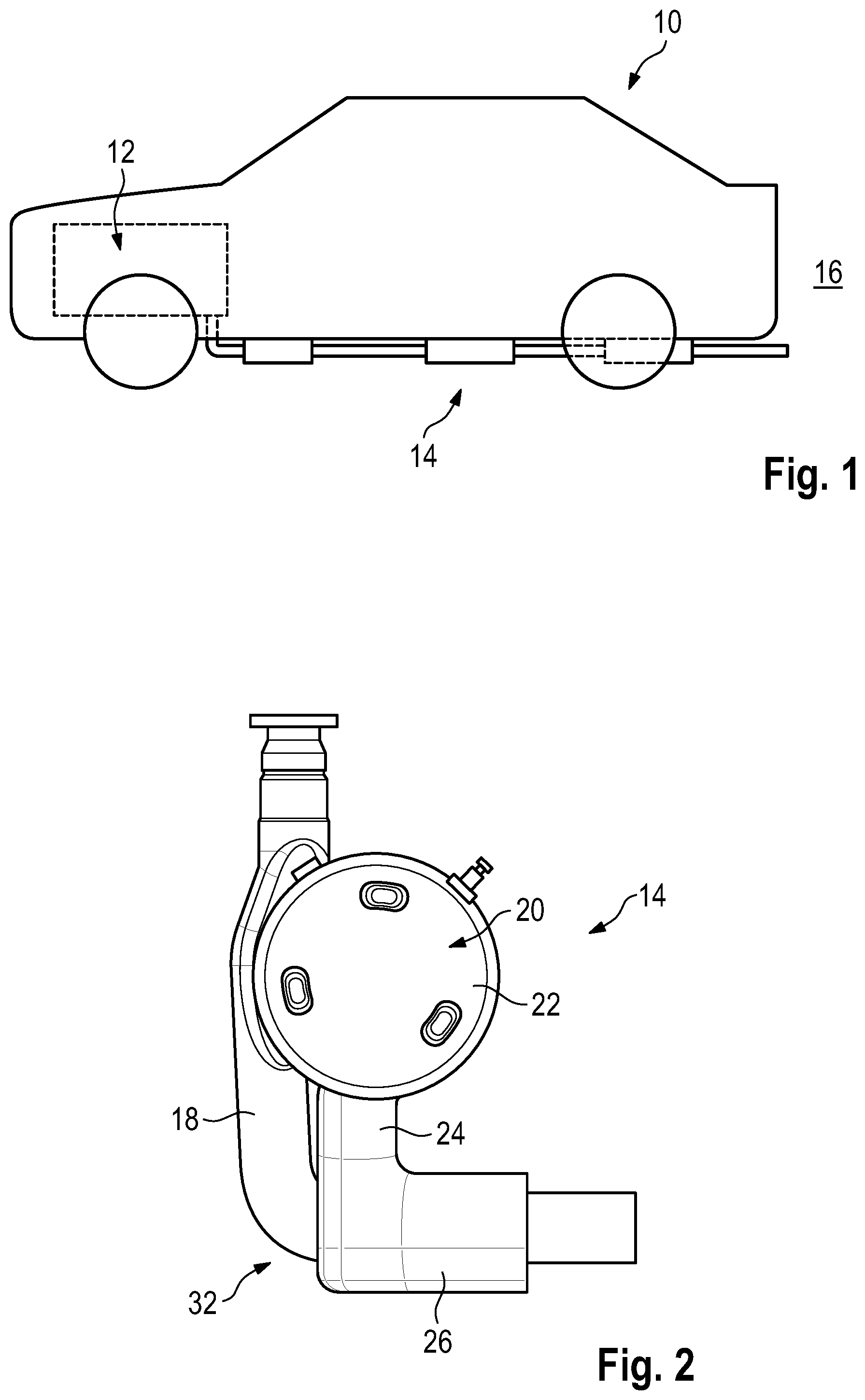
[0029] FIG. 1 shows a schematic view of a motor vehicle according to the disclosure with an exhaust system according to the disclosure,
[0030] FIG. 2 shows the exhaust system according to the disclosure in a view from above,
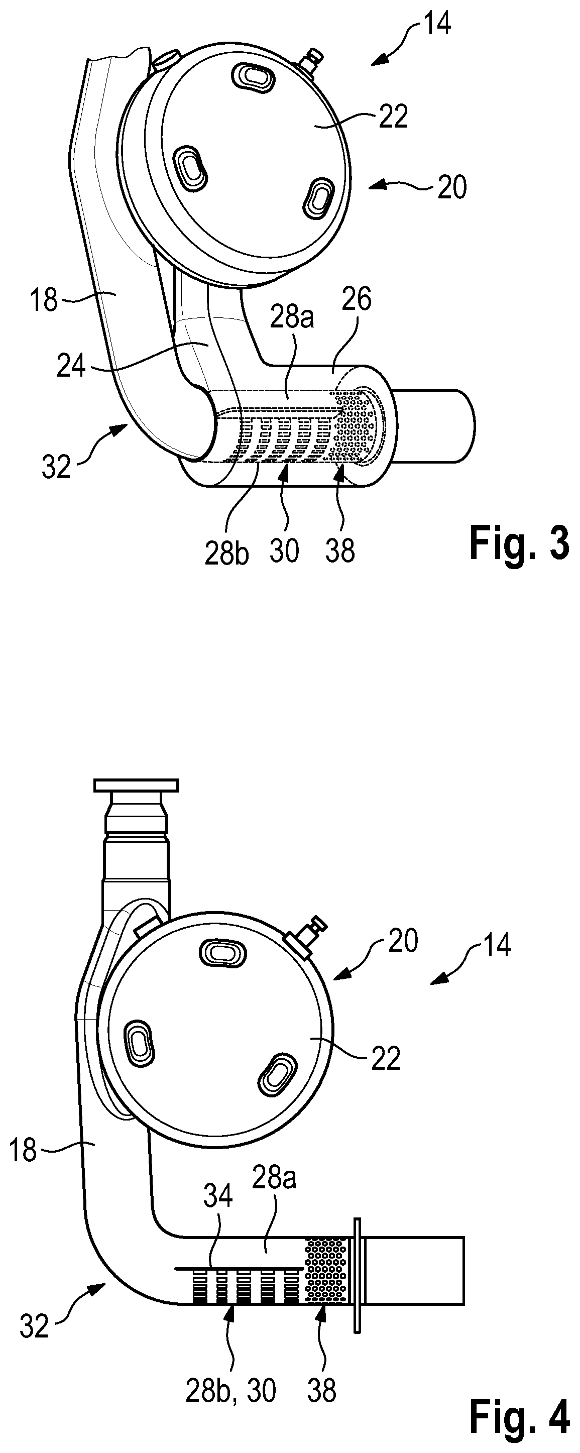
[0031] FIG. 3 shows a perspective view of the exhaust system from FIG. 2, wherein a sound line and a sound coupling-in line are represented transparent,
[0032] FIG. 4 shows the exhaust system from FIG. 2 in a view from above, wherein the sound line and the sound coupling-in line are omitted,
[0033] FIG. 5 shows a perspective view of the exhaust system from FIG. 2, wherein, as in FIG. 4, the sound line and the sound coupling-in line are omitted,
[0034] FIG. 6 shows a schematic detail view of a radial rib of the exhaust system from FIG. 2,
[0035] FIG. 7 shows a schematic detail view of a radial rib of the exhaust system from FIG. 2 according to an alternative design and
[0036] FIG. 8 shows a schematic detail view of a radial rib of the exhaust system from FIG. 2 according to a further alternative design.
DETAILED DESCRIPTION
[0037] FIG. 1 shows a motor vehicle 10 with an internal combustion engine 12 which is coupled to an exhaust system 14. Thus, the exhaust gas produced by the internal combustion engine 12 is conducted into the surroundings 16 via the exhaust system 14.
[0038] The exhaust system comprises an exhaust-gas line 18 routing the exhaust gas and an active silencing device 20.
[0039] The active silencing device 20 has a sound-generating unit 22 which comprises, for example, a loudspeaker and a sound line 24. A sound coupling-in line 26 is connected to the sound line 24 downstream.
[0040] A center axis of the sound line 24 runs substantially along a radial direction of the sound coupling-in line 26. The center axes of the sound line 24 and the sound coupling-in line 26 are thus substantially perpendicular to each other.
[0041] Furthermore, the sound coupling-in line 26 surrounds the exhaust-gas line 18 substantially concentrically on the outside. The center axes of the sound coupling-in line 26 and the exhaust-gas line 18 are thus substantially coincident.
[0042] The active silencing device 20, more precisely the sound-generating unit 22, is acoustically coupled to an exhaust gas flow present inside the exhaust-gas line 18. Here, sound generated by the sound-generating unit 22 is conducted into the sound coupling-in line 26 via the sound line 24 and thus passes into an annular space which is formed by the sound coupling-in line 26 and the exhaust-gas line 18.
[0043] The portion of the exhaust-gas line 18 running inside this annular space can be subdivided into an axial portion facing the sound line 24 and an axial portion, connected downstream thereto, facing away from the sound line 24.
[0044] In the embodiment represented, the axial portion facing the sound line 24 and the axial portion facing away from the sound line 24 are directly adjacent to each other.
[0045] Here, a first perforation 38 is provided in the axial portion facing away from the sound line 24. The axial portion facing the sound line 24 is designed perforation-free in a portion, as will be explained later.
[0046] The first perforation 38 runs around the whole periphery of the axial portion facing away from the sound line 24.
[0047] Here, the openings of the first perforation 38 have a substantially round cross section. Within the axial portion facing the sound line 24, the exhaust-gas line 18 furthermore comprises a peripheral portion 28a facing the sound line 24 and a peripheral portion 28b facing away from the sound line 24. In the embodiment example represented, the two peripheral portions 28a, 28b are complementary to each other to form the whole periphery of the exhaust-gas line 18.
[0048] A second perforation 30 is provided in the peripheral portion 28b facing away from the sound line 24. The peripheral portion 28a facing the sound line 24 is designed perforation-free.
[0049] The sound generated by the sound-generating unit 22 which has already reached the abovementioned annular space, can thus interact with the exhaust gas flow present inside the exhaust-gas line 18 via the first perforation 38 and/or the second perforation 30.
[0050] Here, the openings comprised by the second perforation 30 each have a substantially rectangular cross section, wherein the short sides of the rectangle are each oriented in peripheral direction and the long sides of the rectangle are each oriented in axial direction of the exhaust-gas line 18.
[0051] Furthermore, the exhaust-gas line 18 has an axial bend 32 in an area upstream of the sound coupling-in line 26 which is designed as a 90.degree. bend in the embodiment example represented.
[0052] The second perforation 30 and the axial bend 32 are arranged relative to each other such that the second perforation 30 is positioned downstream of a convex area of the axial bend 32.
[0053] Moreover, the exhaust system 14 represented comprises a radial rib 34 in each of the border areas between the peripheral portion 28b facing away from the sound line 24 and the peripheral portion 28a facing the sound line 24.
[0054] These can be designed in different ways.
[0055] In the variant according to FIG. 6, the radial rib 34 is attached to an inner surface of the sound coupling-in line 26 and extends in the direction of the exhaust-gas line 18. Here, a radial distance 36 can be provided between the end of the radial rib 34 lying inside and the exhaust-gas line 18. Equally, the radial rib 34 can touch the exhaust-gas line 18 or be connected thereto.
[0056] Alternatively, according to FIG. 7, the radial rib 34 can be attached to the exhaust-gas line 18 and extend in the direction of the sound coupling-in line 26. A radial distance 36 can again be provided which results between the outer end of the radial rib 34 and the sound coupling-in line 26. It is equally conceivable that the radial rib 34 touches the sound coupling-in line 26 with its outer end or is connected to same.
[0057] Instead of a single radial rib 34 in each border area between the peripheral portion 28a facing the sound line 24 and the peripheral portion 28b facing away from the sound line 24, a radial rib pair can also be provided which comprises radial ribs 34a, 34b. In this connection, the radial rib 34a is attached to the sound coupling-in line 26 and extends in the direction of the exhaust-gas line 18. In contrast, the radial rib 34b is attached to the exhaust-gas line 18 and extends in the direction of the sound coupling-in line 26.
[0058] In peripheral direction, the radial ribs 34a, 34b are only slightly spaced apart from each other or touch each other.
[0059] In radial direction, the radial rib 34a radiating from the sound coupling-in line 26 has a radial distance 36a from the exhaust-gas line 18 at its inner end. The radial rib 34b radiating from the exhaust-gas line 18 leaves a radial distance 36b free between its outer end and the sound coupling-in line 26.
[0060] In all variants, the radial ribs 34, 34a, 34b are shorter in an axial direction of the exhaust-gas line 18 and of the sound coupling-in line 26 arranged concentric thereto than the sound coupling-in line 26. Thus, there is an axial portion of the sound coupling-in line 26 in which there can be flow around the radial ribs 34, 34a, 34b in peripheral direction of the exhaust-gas line 18. To be more precise, the radial ribs 34, 34a, 34b extend merely in the area of the second perforation 30.
[0061] The mode of operation of the exhaust system 14 is as follows.
[0062] The sound generated by the sound-generating unit 22 flows via the sound line 24 into the sound coupling-in line 26. There, it enters into the inside of the exhaust-gas line 18 via the openings of the first perforation 38. Furthermore, after the sound has flowed around the radial ribs 34, 34a, 34b in the area of the first perforation 38, it also passes into the inside of the exhaust-gas line 18 via the openings of the second perforation 30. In this way, a sound carried by the exhaust gas flow inside the exhaust-gas line 18 is actively muffled.
[0063] However, hot exhaust gas can also flow via the openings of the first perforation 38 and the second perforation 30 from the inside of the exhaust-gas line 18 into the annular space formed by the exhaust-gas line 18 and the sound coupling-in line 26. The active silencing device 20 and in particular the sound-generating unit 22 are to be protected against these hot exhaust gases.
[0064] Exhaust gas exiting via the openings of the second perforation 30 must first flow around the radial ribs 34, 34a, 34b on its path in the direction of the sound-generating unit 22. Here, the radial ribs 34, 34a, 34b represent a flow obstacle on the one hand and cool the exhaust gas on the other.
[0065] In addition, because of the flow ratios inside the exhaust-gas line 18, a large part of the exhaust gas which has exited via the openings of the second perforation 30 is conducted back inside the exhaust-gas line 18 via the openings of the first perforation 38. This is due to the fact that inside the exhaust-gas line 18 a higher pressure prevails in the area of the second perforation 30 than in the area of the first perforation 38. In the annular space, the pressure ratios are reversed, with the result that a higher static pressure prevails in the area of the first perforation 38. This also serves to protect the sound-generating unit 22 against high temperatures.
[0066] A direct flow of hot exhaust gas into the sound-generating unit 22 is also prevented in that the peripheral portion 28a facing the sound line 24 is designed perforation-free.
[0067] Although various embodiments have been disclosed, a worker of ordinary skill in this art would recognize that certain modifications would come within the scope of this disclosure. For that reason, the following claims should be studied to determine the true scope and content of this disclosure.
* * * * *
D00000
D00001
D00002
D00003
D00004
XML
uspto.report is an independent third-party trademark research tool that is not affiliated, endorsed, or sponsored by the United States Patent and Trademark Office (USPTO) or any other governmental organization. The information provided by uspto.report is based on publicly available data at the time of writing and is intended for informational purposes only.
While we strive to provide accurate and up-to-date information, we do not guarantee the accuracy, completeness, reliability, or suitability of the information displayed on this site. The use of this site is at your own risk. Any reliance you place on such information is therefore strictly at your own risk.
All official trademark data, including owner information, should be verified by visiting the official USPTO website at www.uspto.gov. This site is not intended to replace professional legal advice and should not be used as a substitute for consulting with a legal professional who is knowledgeable about trademark law.