System Having A Ground Drilling Device And An Input Device, Method For Controlling The Operation Of A Ground Drilling Device And Use Of A Ground Drilling Device
Jostes; Lucas
U.S. patent application number 16/782665 was filed with the patent office on 2020-09-17 for system having a ground drilling device and an input device, method for controlling the operation of a ground drilling device and use of a ground drilling device. The applicant listed for this patent is TRACTO-TECHNIK Gmbh & Co. KG. Invention is credited to Lucas Jostes.
| Application Number | 20200291770 16/782665 |
| Document ID | / |
| Family ID | 1000004887845 |
| Filed Date | 2020-09-17 |
| United States Patent Application | 20200291770 |
| Kind Code | A1 |
| Jostes; Lucas | September 17, 2020 |
SYSTEM HAVING A GROUND DRILLING DEVICE AND AN INPUT DEVICE, METHOD FOR CONTROLLING THE OPERATION OF A GROUND DRILLING DEVICE AND USE OF A GROUND DRILLING DEVICE
Abstract
A system comprising a ground drilling device having a control device for operating the ground drilling device, wherein the system comprises an input device functionally coupled to the control device for entering at least one parameter for the operation of the ground drilling device, particularly a parameter bringing about a starting of the drilling with the ground drilling device or a stopping of the drilling performed with the ground drilling device, wherein the input device is designed as a remote control.
| Inventors: | Jostes; Lucas; (Finnentrop, DE) | ||||||||||
| Applicant: |
|
||||||||||
|---|---|---|---|---|---|---|---|---|---|---|---|
| Family ID: | 1000004887845 | ||||||||||
| Appl. No.: | 16/782665 | ||||||||||
| Filed: | February 5, 2020 |
| Current U.S. Class: | 1/1 |
| Current CPC Class: | E21B 47/13 20200501; E21B 7/022 20130101 |
| International Class: | E21B 47/13 20060101 E21B047/13; E21B 7/02 20060101 E21B007/02 |
Foreign Application Data
| Date | Code | Application Number |
|---|---|---|
| Feb 15, 2019 | DE | 10 2019 001 107.4 |
Claims
1. System comprising a ground drilling device having a control device for operating the ground drilling device, wherein the system comprises, an input device functionally coupled to the control device for entering at least one parameter for the operation of the ground drilling device, particularly a parameter bringing about a starting of the drilling with the ground drilling device or a stopping of the drilling performed with the ground drilling device, wherein the input device is configured as a remote control.
2. System according to claim 1, wherein the entry of the at least one parameter is a setting of a torque applied to a drill string of the ground drilling device; a setting of a rotational speed applied to a drill string of the ground drilling device; a setting of a linear advancing force of a drill string; a setting of a linear advancing speed of a drill string; a setting of an impact rate of a main piston; a setting of an impact amplitude of a main piston; a setting of a flow rate of drilling mud; a setting of the pressurization of drilling mud; a lubricating of the drill string; a changing of the drill string; and/or a changing of a drilling head type.
3. System according to claim 1, wherein the input device comprises at least one mechanically operated activating element, being in particular a control stick, a rotary switch and/or a pushbutton.
4. System according to claim 3, wherein the at least one mechanically operated activating element comprises a control stick arranged as an interchangeable unit in a receiving space of the input device.
5. System according to claim 3, wherein the input device comprises at least one capacitive or mechanically operated activating element and/or a radio transmitter, particularly to determine whether an operator is holding the input device.
6. System according to claim 3, wherein the sensitivity of the mechanically operated activating element can be adjusted a) mechanically and/or b) by means of software, which is functionally coupled by means of a sensor and a corresponding element to the activating element.
7. System according to claim 1, wherein the input device comprises at least two mechanically operated activating elements, particularly two pushbuttons, which are present on the input device at least so far apart that a two-hands operation is required.
8. System according to claim 7, further comprising a monitoring device adapted to monitor the operation of the two activating elements for simultaneous operation.
9. System according to claim 1, wherein the input device has a surface on which at least two activating elements are arranged in the area of two neighboring corners and/or opposite edges.
10. System according to claim 9, wherein the input device can be grasped in the area of the corners and/or the edges by one hand of the user and the at least one activating element can be reached by one finger or the thumb of the user.
11. System according to claim 1, wherein the input device is configured as a) a wireline and/or b) a wireless remote control.
12. System according to claim 1, wherein the input device is adapted to use multiple radio bands for the communication with the control device of the ground drilling device.
13. System according to claim 1, wherein the input device comprises multiple antennas.
14. System according to claim 1, wherein the input device has a status display to indicate the state of a power supply, a transmission of data and/or signals from the input device to the control device, and/or an error message.
15. System according claim 1, further comprising at least one protective shield for at least one mechanically operated activating element, wherein extension of the protective shield transversely to the surface on which the activating element is arranged being equal to or greater than the extension of the activating element transversely to the surface, in order to prevent an unintentional operation of the activating element.
16. System according to claim 1, wherein the input device has a mechanically firm structure which is adapted to the portion of the human body of an operator, particularly a finger.
17. System according to claim 1, wherein the input device has an attachment for a carrying strap of an operator.
18. System according to claim 1, wherein the input device comprises an element of a connection pair, which can interact mechanically and/or electrically with a further element of the connection pair which is situated at the ground drilling device.
19. System according to claim 1, wherein the ground drilling device comprises a control stick which is larger than a control stick on the input device.
20. System according to claim 1, further comprising an indicator device for displaying at least one parameter for the operation of the ground drilling device, which is adapted such that the indicator device can be mechanically connected to the input device and/or the indicator device can be mechanically connected by a coupling to the ground drilling device.
21. System according to claim 20, wherein the input device has an inner contour which is adapted to the outer contour of the indicator device, and the input device surrounds the indicator device at least partly along a section of the outer contour of the indicator device.
22. System according to claim 20, wherein the indicator device is a tablet, an Ipad, or a notepad.
23. System according claim 20, wherein the indicator device comprises a control unit which is adapted for a context-sensitive display of information on the indicator device.
24. System according to claim 20, wherein the indicator device and the input device are functionally connected such that when data is entered on the input device the entry is displayed by means of the indicator device.
25. System according to claim 20, wherein the indicator device comprises an entry area which is adjacent to the input device when the input device and the indicator device are connected to each other.
26. System according claim 20, wherein the indicator device is connected to the control device of the ground drilling device in a) wireless or b) wireline manner.
27. System according to claim 26, wherein the indicator device is adapted for a wireless data exchange by means of WLAN.
28. System according to claim 20, wherein the input device and the indicator device have separate power supplies.
29. System according to claim 20, wherein the indicator device comprises means of communication for the transfer of data and/or signals between the indicator device and a locating system for the drilling head.
30. System according to claim 20, wherein the indicator device has a data output which is provided in particular for putting out a record of the operation of the ground drilling device.
31. System according to claim 20 further comprising a detection device adapted to detecting the drill string at its end side (a) in the area of the ground drilling device and/or (b) in the area of a target pit of an earth borehole being created, the detection device comprising transmission means which are designed to send signals to the indicator device and/or to the control device, wherein the indicator device and/or the control device are designed to process the signals of the detection device such that the signals are presented on the indicator device for a user.
32. System according to claim 31, wherein the detection device is a camera, a zone scanner and/or a motion scanner.
33. Method for controlling the operation of a ground drilling device, comprising: entering at least one parameter for the operation of the ground drilling device, particularly a parameter bringing about a starting of the drilling with the ground drilling device or a stopping of the drilling performed with the ground drilling device, wherein the entering of the at least one parameter is done by a remote control.
34. In a ground drilling device having a control device for the operating of the ground drilling device, a method comprising providing a remote control as an input device which is functionally coupled to the control device to enter at least one parameter for the operation of the ground drilling device, the at least one parameter including a parameter bringing about a starting of the drilling with the ground drilling device or a stopping of the drilling performed with the ground drilling device.
Description
FIELD OF INVENTION
[0001] The invention relates to a system having a ground drilling device with a control device for operating the ground drilling device, wherein the system moreover comprises an input device functionally coupled to the control device for entering at least one parameter for the operation of the ground drilling device, a method for controlling the operation of a ground drilling device, and a use of a ground drilling device.
BACKGROUND
[0002] Ground drilling devices are generally operated by a user who is positioned at a driver's station, usually an operator's cabin. At the driver's station, there is arranged a seat for an operator and the operator can control the operation of the ground drilling device by means of at least one activating element, particularly a multifunction joystick. Usually other persons besides the operator are needed on site, in order to monitor and/or conduct the operation and the success or activities required for the drilling.
SUMMARY
[0003] The problem which the invention proposes to solve is therefore to create a system, a method, and a use with which the expense for making a borehole by means of the ground drilling device can be reduced, especially the expense in the form of providing a smaller number of operating and/or monitoring persons.
[0004] The key idea of the invention is to configure an input device, which is intended for the entry of at least one parameter for the operation of the ground drilling device, as a remote control. The configuring of the input device as a remote control creates the possibility of the operator, heretofore located at the driver's station, choosing their location more freely in regard to the control of the ground drilling device. No longer must the operator remain at the driver's station in order to control the ground drilling device. Thanks to the free possible positioning of the operator, he can be present at other possible locations while controlling the ground drilling device and thus be present at the same time as controlling the ground drilling device at a location where formerly another operator had to be present in order to perform or monitor an activity in connection with the introducing of the earth borehole in the soil. Since the activity can now also be performed by the operator otherwise present at the driver's station, the additional operator is not needed. The operator formerly required can now be given other jobs, so that the work force and/or the costs of providing the work force for the introducing of a ground drilling device can be reduced. An added value is possible for the firm utilizing the ground drilling device.
[0005] The invention creates a system comprising a ground drilling device having a control device for operating the ground drilling device. The system moreover comprises an input device functionally coupled to the control device for entering at least one parameter for the operation of the ground drilling device. In particular, the parameter may bring about a starting of the drilling with the ground drilling device or a stopping of the drilling performed with the ground drilling device. The input device is designed as a remote control.
[0006] A "ground drilling device" in the sense of the specification encompasses any device which moves in particular a drill string having rod sections in an existing or yet to be created conduit in the soil, in order to create or widen a borehole, particularly a horizontal borehole (HD), or to draw pipelines or other long bodies into the soil. The ground drilling device may be in particular a HD device. The term "HD" (horizontal drilling) in the sense of the present specification encompasses in particular an at least partly horizontal borehole or conduit or pipeline. A ground drilling device may be in particular a device driving a drill string operating by displacing earth, and introducing the drill string into the earth by rotation and/or translation in the longitudinally axial direction of the drill string. A borehole can be introduced into the soil by pulling or pushing on the drill string. The term "rod section" in the sense of the specification encompasses not just rigid force transmitting elements which can be connected directly or indirectly to each other and which can be used in a ground drilling device.
[0007] A front-end section of the drill string may be configured as a drilling head or drilling tool. Moreover, the drill string may have a probe housing, particularly in a front-end region.
[0008] The term "control device" in the sense of the specification encompasses an embodiment of a control system by means of which a directional influencing of the ground drilling device is possible in operation, i.e., during the making or at the starting or stopping of an earth borehole. The control device in particular may be electrical or electronic. The parameters entered by an operator can be used by the control device as input for the operation of the ground drilling device--optionally transformed and/or processed into electrical signals. The ground drilling device can thus be operated or controlled by means of the entering of a parameter, possibly transformed into an electrical signal.
[0009] By a "parameter" in the sense of the specification is meant a data entry with which a directional influencing of the operation of the ground drilling device is possible. The parameter may be relayed as an input signal to the control device, by means of which the control device controls the operation of the ground drilling device. A parameter may, for example, bring about a starting of the drilling with the ground drilling device or a stopping of a drilling being carried out with the ground drilling device. For example, it is possible for an operator to enter the parameter "Start" and an input signal appropriately coordinated with the data entry will be relayed to the control device, which causes a starting of the drilling. In similar fashion, an operator may enter the parameter "Stop" and a corresponding input signal related to this will be relayed to the control device, which causes a stopping of the drilling performed with the ground drilling device. Other parameters influencing or altering the operation of the ground drilling device are possible, these parameters being entered by an operator and being transformed by the input device into an input signal and relayed to the control device.
[0010] The term "input device" in the sense of the specification encompasses any electrical or electronic device which is suited to transforming a data entry by an operator into an electrical signal, which may be relayed to the control device with no further processing or by way of an interposition of circuitry for processing of the signal, particularly a processing in one or more circuits, such as an amplifier, in order to be used as input or as an input signal of the control device. The input device can be understood as being an interface between an operator and the control device. The input device may comprise a portable power supply, particularly in the form of one or more batteries, storage cells, or the like.
[0011] The input device in particular may comprise a processor, being designed as a computer with electronic circuits, in order to execute commands. The input device may have an operating system, which can be modified for example for an improvement and/or adaptation to changes in a ground drilling device. A change in the operating system can then only be allowed, in particular, with a password and/or when the input device is connected to an interface of a computer, a dongle, or the like. In particular, the processor can recognize the data entry of an operator in the form of parameters, retrieve them, process them, forward them on, and/or handle other commands of a program. The processor can work off a program which requests or receives the data input of an operator, process the data entry of the operator, make adjustments to the data entry of the operator, transfer the data input to the control device and/or receive, process, and/or transform signals from the control device.
[0012] The term "functionally coupled" encompasses in the sense of the specification a connection of the mentioned devices, particularly a unidirectional or bidirectional one, in order to provide signals from one of the devices, particularly the input device, and to receive signals with the other device, particularly the control device, and/or to process the signals received. The functional coupling can be direct or indirect through the interposition of other elements or devices.
[0013] A "remote control" encompasses in the sense of the specification a handheld electrical or electronic device which is suited to controlling the operation of the ground drilling device at a distance from it by the entry of a parameter. In the sense of the specification, "at a distance from the ground drilling device" should be taken to mean that a direct entry by means of a device fastened to the ground drilling device is not necessary. In particular, an operator outside the driver's station of the ground drilling device can control the operation of the ground drilling device by entry of a parameter for the operation of the ground drilling device.
[0014] In one preferred embodiment, the entry of the at least one parameter is [0015] a) a setting of a torque and/or a rotational speed applied to a drill string of the ground drilling device, (b) a setting of a linear advancing force and/or a linear advancing speed of a drill string, (c) a setting of an impact rate of a main piston, (d) a setting of an impact amplitude of a main piston, (e) a setting of a flow rate and/or a pressurization of drilling mud, (f) a changing of the drill string, (g) a lubricating of the drill string, and/or (h) a changing of the drilling head type. Consideration may be given to which string is involved. In particular, in a double-pipe string, the torque and/or the rotational speed can be chosen independently for an inner pipe string, so that both torque and/or rotational speed can be set independently for an inner pipe string and/or outer pipe string. In this way, basically any entry can be done which is relevant for the drilling operation of the ground drilling device. Besides the starting or stopping of a drilling performed with the ground drilling device, the aforementioned parameters can be relayed to the control device.
[0016] For the setting of a torque/rotational speed applied to the drill string of the ground drilling device, a signal can be relayed from the control device in dependence on the parameter entered by the operator using the input device to the drive unit of the ground drilling device, which is connected to the drill string, so that the torque/rotational speed chosen by the operator can be adjusted. The parameter may be a signal corresponding to the magnitude of the torque/rotational speed. The setting of a linear advancement of the drill string can set both the force or the pressure and/or the speed with which the drive acts on the drill string connected to the drive. The setting of the linear advancement may also include whether the linear advancement is a tensile or compressive force, i.e., whether the drill string is pulled or pushed through the soil. Accordingly, the term advancement encompasses both directions, both a pulling and a pushing of the drill string, so that a pulling or a pushing force can be applied to the drill string. Hence, the parameter can be a signal corresponding to the tensile or compressive force. When introducing a borehole in the soil, drilling mud may be used, particularly in the form of bentonite. The drilling mud can be taken through the drill string and emerge at the front end region of the drill string. The parameter set can be a flow rate or pressure of the drilling mud, which can be adapted to the conditions in the soil. When drilling with a drill string, it is necessary to lengthen the drill string during the course of the drilling, and in particular additional rod sections are connected to the drill string already introduced in the soil. For this, a data entry may be needed to perform a string change, i.e., the connecting of an additional rod section, particularly one from a rod magazine, to the drill string already introduced. Thus, the parameter may be an activation corresponding to the command "Perform string change now". During the string change, the drill string already introduced in the soil is clamped, in order to fix the axial and/or angular position of the already introduced drill string. Moreover, the entry of the parameter may involve a changing of the drill head type, which may be required especially when, after performing a pilot borehole, i.e., a first borehole, which has been made for example by pushing in the soil, the drill head type is changed to a widening drill head, which is pulled through the previously created pilot borehole in order to widen it.
[0017] Insofar as the ground drilling device is designed as a percussion drilling device, the stroke rate of the main piston of the percussion drilling device and/or the stroke amplitude of the main piston of the percussion drilling device can be adjusted. The term "percussion drilling device" or "displacement hammer", which is used basically synonymously with percussion drilling device, encompasses in the sense of the specification a self-propelled impact apparatus which works by displacement of soil and can introduce a conduit or a pipe into the soil by percussion. The term percussion drilling device encompasses earth displacement devices in which the drilling head tip is arranged lengthwise movably in a housing. The drilling head tip may be in particular a drill bit. A percussion drilling device can be both a single-stroke and a multiple-stroke device. In a single-stroke device, the main piston strikes the drilling head tip and at the same time the housing. In a multiple-stroke device, particularly a two-stroke device, the main piston at first strikes the drilling head tip, which moves ahead during the first stroke. The housing is struck in a following stroke, particularly in the second stroke. Tip resistance and casing friction are separate in a multiple-stroke device and thus are easier to overcome.
[0018] In one preferred embodiment, the input device comprises at least one mechanically operated activating element. The mechanically operated activating element may be any mechanically or manually operated activating element. A rotary switch, a control stick and/or a pushbutton are preferred embodiments of a mechanically operated activating element. Different kinds of activating elements are possible on the input device. Multiple activating elements of the same kind may be provided on the input device.
[0019] A control stick in the sense of the specification is an activating element for the entering of two-dimensional signals in particular. A control stick may comprise an element extending from a surface, which can generally be tilted in multiple directions. The element can be configured in particular as a rod, a piston, a stick, or a lever. The element can extend from a surface at a height not greater than 7 cm, preferably 6 cm, preferably 5 cm, preferably 4 cm, preferably 3 cm, preferably 2 cm, preferably 1 cm. The diameter of the element may in particular be less than 5 cm, preferably 4 cm, preferably 3 cm, preferably 2 cm. A control stick in the sense of the specification may also be called an analog stick or a joy stick and it may be equivalent in function to this. The term control stick also encompasses a control pad with which an entry of two-dimensional signals is possible. The control stick may generate a signal which is dependent on the position of the element or the control pad in relation to a standard or resting position of the element or the control pad. It may be provided that the control stick provides individual electric signals when activated and/or continuously provides an electric signal in the form of voltages and/or currents, wherein a potentiometer can be used respectively for one of the dimension in which the element or the control pad can be tilted, for example one potentiometer for the up/down position and one potentiometer for the left/right position. The voltage can change due to the change in position or attitude of the element or control pad of the control stick in relation to the resting or standard position. The size and/or arrangement of the control stick on the input device may be adapted such that an activation is possible by means of the thumb or a finger of an operator, in particular an activation of the control stick is possible without grabbing the control stick. Insofar as the control stick is designed to generate signals in dependence on a movement in at least two dimensions, this also includes the possibility that an entry can be provided for a control of the operation of the ground drilling device by means of a control stick in which the control stick generates no signals in regard to the movement in one of the dimensions and/or signals in regard to the movement in one of the dimensions are not taken into account, or do not need to be taken into account by the control device.
[0020] A rotary switch or rotary knob in the sense of the specification may comprise a potentiometer or be formed by such. Advantageously, the rotary switch is substantially maintenance-free and not sensitive to vibrations; moreover, in the switched-off state, a turning of the rotary switch has no effect.
[0021] A pushbutton in the sense of the specification is an activating element which can be configured as a subassembly which makes or breaks an electrically conductive connection. The pushbutton may be designed as a toggle switch or a simple pressure switch. It has been found to be advantageous for the operating stroke of a pushbutton to be at least more than 2 mm, in order to count as a "wanted" activation. Preferably, activating strokes of more than 2.3 mm are used, and when gloves are worn then activating strokes of more than 3 mm, preferably more than 5 mm, particularly preferably more than 6 mm, even further preferably more than 7 mm may be provided. For the diameter of a pushbutton, it has been found to be advantageous for the diameter of the pushbutton to be more than 5 mm, particularly more than 7 mm, for an activation by means of the finger of the operator. For an activation by means of the thumb of the operator, the diameter of the pushbutton can advantageously be more than 15 mm, preferably more than 17.5 mm, particularly more than 20 mm.
[0022] A selection of mechanically operated activating elements may be provided at the input device. In particular, customary activating elements of the prior art can be used to allow the operator the also customary entry possibilities for the control of the ground drilling device. The size and/or arrangement of the activating elements may vary relative to the prior art, in particular a control stick on the input device may be smaller than a multifunction joystick situated in the driver's station.
[0023] In one preferred embodiment, at least one mechanically operated activating element, particularly a control stick, is arranged as an interchangeable unit in a receiving space of the input device. In this way, the possibility can be created of quickly replacing an activating element needed for the operation of the ground drilling device in order to enable the most continuous possible operation of the ground drilling device by the operator. Such a simple replacement may be advantageous, given the use of the input device outside the driver's station, since the activating element may be subjected to greater wear and tear.
[0024] In one particularly preferred embodiment, the input device may comprise at least one capacitive or mechanically operated activating element and/or a radio transmitter, particularly to determine whether an operator entrusted with operation of the ground drilling device is holding the input device or grasping it with his hands. Accordingly, an activating element and/or a radio transmitter may be provided to determine whether an operator can operate the input device or is located in its near field. A capacitive or mechanically operated activating element can recognize the presence of the operator as well as a radio transmitter. For example, a mechanically operated activating element can determine whether the operator is operating the respective activating element in order to allow data entry and/or further operating of the ground drilling device and not to place it in a protected condition. For example, it may be provided that the entry of a parameter only occurs when the respective activating element has positively recognized that the operator is holding the input device or grasping it with their hands or is operating the activating element at the same time. In this way, it is possible to determine for example whether the operator has set the input device aside, for example in order to perform work on the ground drilling device or gain access to it, while the ground drilling device is still performing an earth drilling and driving the drill string. In such an event, a switching off or a placing of the ground drilling device in a resting condition can be done. The input device in such a case relay to the control device a signal corresponding to a parameter signifying, in a real instruction, "Produce resting condition" or "Emergency shut off". It may be provided that the "resting condition" of the ground drilling device differs from the condition of the ground drilling device after an "emergency shut-off"; in an "emergency shut-off", a shutting off of the ground drilling device may occur, whereas in a "resting condition" the units and/or drives of the ground drilling device continue to be switched on but are not driven.
[0025] In one preferred embodiment, the sensitivity of the mechanically operated activating element can be adjusted a) mechanically and/or b) by means of software, which is functionally coupled by means of a sensor and a corresponding element to the activating element. This can create the possibility for the operator to adjust the sensitivity, particularly that of a control stick or a rotary switch, even under different conditions, such as with or without wearing gloves. For example, two different settings are possible for the sensitivity of a control element: 1) operation with gloves or 2) operation without gloves. It may also be provided that the sensitivity can be set in dependence on the kind of the entry or the parameter. The setting can be undertaken by the processor in the input device.
[0026] In one preferred embodiment, the input device comprises at least one particularly two mechanically operated activating elements, particularly one or two pushbuttons, which are present on the input device at least so far apart that a two-hands operation is required. This can create a so-called dead man's switch, with which it can be verified that an operator is present or able to act. If it is recognized that no operation of one of the activating elements is done, then it may be concluded that the operator is not present and/or capable of acting, so that a signal or a switching action may be triggered. This can achieved a higher degree of safety during the operation of the ground drilling device. For example, an operator may be prompted by means of a haptic signal, a visual indication, and/or an acoustic signal, to operate the activating element or both of them; if no operation occurs, a signal or a switching action may be triggered, which switches the ground drilling device to a resting state or switches it off. The providing of two mechanically operated activating elements, only one of which need be used as a so-called dead man's switch, can provide the advantage that--when the mechanically operated activating elements are present both right and left on the input device--the input device can be easily and ergonomically operated by both right-handed and left-handed operators. Accordingly, it will be sufficient to configure a dead man's switch either on the left or the right side. However, the providing of the two options, both right and left, takes account of the possible requirements of the operator.
[0027] In one particularly preferred embodiment, a monitoring device is present, which can be part of the processor. The monitoring device is adapted to verifying the operation of two activating elements at the same time. In addition or alternatively, it may be provided that a monitoring is done to ensure that the simultaneously operated activating elements are not operated again within a predetermined time window. With the aid of the monitoring device, a time difference can be set in regard to the "simultaneity" of the triggering of the two activating elements in the form of a tolerance. There may also be a setting of the time in which the activating elements need to be released once more. A simple design of a dead man's switch is possible.
[0028] The input device may have a circumferential outer contour, particularly an interrupted or closed one, which may enclose an inner contour or interior of the input device. The circumferential outer contour may be substantially rectangular, square, polygonal, round, circular and/or elliptical over the entire area or also only for a portion. Mixed shapes and combinations of the mentioned shapes are possible. In particular, it may be provided that the input device is substantially rectangular or cuboidal and has a dimension in the range of 15 cm to 50 cm in width, preferably 20 cm to 40 cm in width, 10 cm to 30 cm in length, preferably 15 cm to 25 cm in length, and 3 cm to 15 cm in height, preferably 5 cm to 10 cm in height.
[0029] It may be provided that the input device has at least one protrusion or multiple protrusions, particularly two of them, particularly in regard to one of the aforementioned shapes, which may be adapted for grasping by means of the hands of the operator, in particular, the protrusion or the protrusions may be configured as a handle. Preferred is a handle configuration which can be embraced by one hand of the operator. The protrusion or the protrusions may project beyond the rectangular, square, polygonal, round, circular and/or elliptical shape of the input device. The mechanically operated activating elements in particular can be fashioned on one of the protrusions or on each of them. The protrusions may be configured on the input device such that a surface facing toward the operator results by means of the protrusion or the protrusions, forming a surface which can lie in a plane in particular. It may be provided that the protrusions stand off from a surface with the aforementioned shape, particularly to form entirely or partially a holder, particularly one with the circumferential outer contour, for an indicator device as described below in the specification. The protrusion or protrusions may stick out from a base surface or a base plate. The protrusion or protrusions may form, at least for a portion, an edge on a base plate having an aforementioned shape. The protrusion or protrusions may be offset forwards in relation to the base plate. If multiple protrusions are present, the protrusions may project in the same direction relative to a base surface or base plate and form an edge thereon. The base plate with the protrusion or protrusions may follow in particular a circumferential outer contour of an indicator device. The base plate can be entirely closed or it may have apertures. A wall may project at least partly or in closed manner at the edge on the base plate, which can enclose at least partially or entirely on the circumference of an indicator device described hereafter in the specification.
[0030] A curved adaptation of the protrusions to the shape of the hands of the operator is possible, particularly as regards the corners of a protrusion. The particular protrusion may be adapted to the dimensions of the hand of the operator; in this way, the input device may be configured in other areas independently of the hands of the operator; it is possible for an adaptation to the dimensions and shape of the hands to be present only in the area of the protrusions. Thus, an adaptation to the dimensions and/or shape of the hands of the operator, possibly involving a smaller structural shape, may only pertain to the protrusions.
[0031] The mentioned protrusion or protrusions for a good grasping by means of one hand of the operator may have a diameter in the range of 3 cm to 5 cm, preferably 3 cm to 4 cm. The length of a protrusion particularly for a good holding by one hand of the operator, particularly in a manner not causing fatigue, may be larger than 10 cm, preferably larger than 15 cm, in order to allow for the possibility of the operator wearing a glove, for example.
[0032] If more than one protrusion is formed on the input device, the protrusions may be formed on opposite sides of the input device. A mirror image symmetry of the protrusions is possible. The mechanically operated activating elements can be formed as mirror images of each other on the protrusions when multiple protrusions are provided.
[0033] When the respective protrusion is grasped by the hand of the operator as intended, a control stick may be arranged on the protrusion in the area of the thumb. Preferably, a control stick is arranged on each of the protrusions in the area of the thumb. Preferably, a mechanically operated activating element fashioned as a control stick element protrudes from a substantially flat or noncurved surface. The control stick may protrude from a surface of the input device facing toward the operator. In particular, a control stick may protrude from a surface parallel to the base surface of the input device, which can be established basically by the circumferential outer contour.
[0034] If a control stick is provided on the input device, a further mechanically operated activating element, particularly a rotary switch, can be arranged on a surface of the protrusion different from the surface for the control stick. Regardless of whether a control stick is provided, a rotary switch can be arranged in particular on a surface of the protrusion extending away from the operator. The surface on which a rotary switch is arranged can make an angle in particular with a surface facing toward the operator when holding the input device or on which a control stick is provided of 10.degree. to 60.degree., preferably 20.degree. to 50.degree.. In particular, the rotary switch may be arranged such that it can be comfortably operated with the index finger or middle finger of the operator when the input device is held, particularly if the operator grasps the protrusion optionally provided on the input device.
[0035] If a control stick is provided on the input device, a pushbutton may be arranged in particular on a surface different from the one provided for the control stick. A pushbutton may be arranged in particular on a surface of the protrusion extending away from the operator when the input device is held. The surface on which the pushbutton may be provided can be opposite the surface from which the control stick extends, if a control stick is provided. The surface on which the pushbutton is arranged can make an angle with a surface on which a control stick is provided of 10.degree. to 60.degree., preferably 20.degree. to 50.degree.. The pushbutton may be arranged in particular so that it can be comfortably operated with the index finger, middle finger, or ring finger of the operator when the operator is holding the input device, particularly when the operator is grasping the protrusion possibly provided.
[0036] It may be provided that a pushbutton and a rotary switch are present on the same surface at a distance from each other, wherein an operation with different fingers of the operator is possible in particular.
[0037] Basically three surfaces may be formed on a protrusion of the input device, on which a mechanically operated activating element can be arranged each time. The surfaces on which a mechanically operated activating element is provided can make an angle with each other. The surfaces may have a curvature. A mechanically operated activating element designed as a rotary switch may be arranged preferably on a surface having a curvature, and the curvature of the surface may basically correspond to the curvature of the rotary switch, so that an operation of the rotary switch can occur in particular over an angle range which is larger than 180.degree., larger than 190.degree., larger than 200.degree., larger than 210.degree., larger than 220.degree., larger than 230.degree., larger than 240.degree., larger than 250.degree., larger than 260.degree., larger than 270.degree., larger than 280.degree., larger than 290.degree., larger than 300.degree.. Thus, an operating of the rotary switch can be easily done by an operator who may be wearing gloves.
[0038] A mechanically operated activating element designed as a pushbutton may be arranged preferably on a surface having a curvature. A pushbutton may have a curvature basically corresponding to the curvature of the surface. It may be provided that an operation of the pushbutton is possible over a large angle range, which may correspond to the angle range of the curvature. An operation may occur even if the pushbutton is not operated in a straight line.
[0039] A structurizing of the input device is possible for at least partial or complete accommodation of a further device, particularly an indicator device described below in the specification, wherein an accommodating in the sense of the specification involves the possibility of a connection between the two devices, particularly the input device and the indicator device, which may be with form fit and/or force locking, in particular.
[0040] In one preferred embodiment, the input device has a not necessarily flat surface on which at least two activating elements are arranged in the area of two neighboring corners and/or opposite edges. The corners and/or edges may also be formed on one or more protrusions. This makes possible an ergonomically favorable arrangement of two activating elements for the person performing the operation. Thus, the principles of an optimal design can be satisfied. Designs conforming to occupational medicine, user friendliness, work science or personal body type of the operator can be taken into account.
[0041] In a particularly preferred embodiment, the input device can be grasped in the area of the corners and/or the edges--possibly in the area of a protrusion--by one hand of the operator. Moreover, in the preferred embodiment, at least one activating element can be arranged so that it can be reached by one finger or the thumb of the user, grasping the corners and/or the edges--possibly at one or more protrusions. It has been discovered that an optimal adaptation is achieved from an ergonomic standpoint, also taking account of work science and user-friendly criteria. For example, the input device may be adapted by the thickness of the corners and/or edges to the operator's hand, taking into account whether or not the operator is wearing gloves.
[0042] In particular, the activating elements arranged in the area of the corners and/or edges may be control sticks. In particular, the control sticks may be arranged on a surface of the input device forming a base surface or situated in parallel with this.
[0043] In one preferred embodiment, the input device is designed as a) a wireline and/or b) a wireless remote control. In one particularly preferred embodiment, the input device is a wireless remote control, which creates the possibility of the operator moving basically freely with the input device, without having to worry about a cable which is connected by the input device to the ground drilling device. A wireline remote control offers the advantage of a substantially undisturbed transmission of signals by the cable.
[0044] In one preferred embodiment, the input device is adapted to use one or more radio bands for the communication with the control device of the ground drilling device. In the sense of the specification, a frequency band means frequency ranges, i.e., partial ranges of the electromagnetic spectrum of electromagnetic waves used for technical communication. It is usual to partition this spectrum by frequency, wavelength, or usage. Different designations of frequency bands are possible, particularly international ones.
[0045] In one preferred embodiment, the input device comprises one or more antennas, in order to provide signal pathways, particularly in a direction to heighten the operating safety of the ground drilling device, for example. It may be provided that a bidirectional transmission of signals is possible by means of an antenna between the input device and the control device. But it may also be provided that at least one antenna is provided for one direction (from the input device to the control device and from the control device to the input device) and different antennas are used for the two directions. The antenna(s) may be connected to the processor of the input device.
[0046] A bidirectional communication between the input device and the control device is possible. For example, the control device may confirm the entering of a parameter or relay to the input device the fact that an error has occurred in the entering and/or transmittal to the control device.
[0047] In one preferred embodiment, the ground drilling device comprises one, two, or more antennas for the communication with the input device. The ground drilling device can use in particular the signal which is the strongest, the best, or the most stable, by means of the control device.
[0048] In one preferred embodiment, the input device has a status display to indicate a state. The status display may be connected to the processor. The status display may involve a state regarding a power supply of the input device, a transmission of data and/or signals from the input device to the control device, a signal strength, an indication that the input device has been switched on or off, and/or an error message. The status display may be reduced to the essential information, so that for example a display only occurs when a particular state is reached--such as a critical one. For example, the status display may be adapted to identify a reduced power supply or a power supply of the input device tending to decline in the near future. Alternatively or additionally, it may be provided that the status display indicates that an error has occurred during the transmittal of data from the input device to the control device. Alternatively or additionally, the status display can indicate that the signals generated by an activating element are defective. Alternatively or additionally, the status display can indicate that an error has been found at the ground drilling device or the control device, particularly one in the form of a signal of a device monitoring a critical state. The status display may be a clear text display, a simple lighting means, particularly a LED, which may be colored. In the case of a simple lighting means, the color of the lighting means may correspond to the state being displayed to the operator. For example, the color may change or a different colored lighting means may be actuated or become lit if the type of condition or the condition changes. For example, it may be provided that, when the ground drilling device is in operation and no error has been detected, a green light is used. If the condition changes in the way of a worsening, for example the power supply has been reduced below a certain degree in terms of its capacity, the color orange may be used. A further reduction or an error may be signaled with the color red. In the area of the status display or as part of the status display, a symbol may be situated or represented, particularly in the form of an imprint, providing information about the status display. For example, a battery symbol may be used for the status display regarding a power supply. An antenna symbol may be used for a status display regarding a transmission error.
[0049] In one preferred embodiment, at least one protective shield for at least one mechanically operated activating element is present, the extension of the protective shield transversely to the surface on which the activating element is arranged being equal to or greater than the extension of the element of a control stick. In this way, an unintentional operation of the activating element can be prevented, and a relatively simple mechanical construction will be sufficient. Thanks to the protective shield, for example, it can be prevented that an input device which is dropped and makes contact with the ground does not operate the activating element due to the effect of the ground surface. The protective shield in addition to the mentioned spatial extension may also be arranged relative to the mechanically operated activating element such that an unintentional operation is largely precluded. It may be preferable for the protective shield to be arranged in spatial proximity to the mechanically operated activating element. The protective shield may extend in multiple directions around the mechanically operated activating element. The protective shield may be present between an outer edge of the input device and the mechanically operated activating element. The protective shield may be interrupted at least partially or be closed, forming a wall between the edge of the input device and the mechanically operated activating element. The wall may extend in two directions with respect to two different edges of the input device. More than two walls are also possible, which may encircle or surround the mechanically operated activating element at least for a portion, as long as the operator continues to have a mechanical access.
[0050] In one preferred embodiment, the input device has a mechanically firm structure which is adapted to the portion of the human body of an operator, particularly a finger of an operator. In this way, an input device can be created which conforms to occupational medicine, user friendly, and/or personal body criteria, in particular making possible a holding with no fatiguing tension in the hands.
[0051] In one preferred embodiment, the input device has an attachment for a carrying strap of an operator, so that the operator is relieved of holding the weight of the input device. More comfortable working is possible, more free of fatigue. It may also be provided that the attachment by means of a carrying strap can be used to carry the input device. The operator can let go of the input device and the input device will still be attached to the operator, for example, on a carrying strap fashioned as a shoulder, neck, or waist strap.
[0052] In one preferred embodiment, the input device comprises an element of a connection pair, which can interact mechanically and/or electrically with a further element of the connection pair which is situated at the ground drilling device. The connection pair may be a pair of elements forming a mechanical and/or electrical connection. The input device can be held securely on the ground drilling device by means of the mechanical connection. By means of an electrical connection, for example, a signal transmission and/or a power transmission is possible. A charging of the battery or the power supply of the input device is possible. The further element of the connection pair may be present in particular at the driver's station at the ground drilling device. By means of the further element of the connection pair at the driver's station, it is possible to use the input device at a fixed position of the ground drilling device, with which the operator is familiar, and where the operator is basically protected against environmental factors.
[0053] In one preferred embodiment, the ground drilling device comprises a control stick which is larger than a control stick on the input device. In this way, the previous data entry possibility through a familiar multifunction joystick can be preserved by means of the control stick for the operator. In particular, the operator will find at the driver's station the previously customary control stick--being larger than the input device. The ground drilling device can be operated at the driver's station in the otherwise customary manner.
[0054] In one preferred embodiment, an indicator device is provided for displaying at least one parameter for the operation of the ground drilling device, the indicator device being adapted such that it can optionally be mechanically connected to the input device and/or the indicator device can be mechanically connected by a coupling to the ground drilling device. On the one hand, it is thus possible for the indicator device to form with the input device a unit which can be manipulated in common and can be held by an operator. On the other hand, it is thus possible for the indicator device to be connected to the ground drilling device and for the input device in turn to be connected to the indicator device, whereby the input device can be indirectly connected mechanically to the ground drilling device. By means of the indicator device, the operation of the ground drilling device can be visualized. The indicator device in particular can be an electrical or electronic display, designed in particular as a liquid crystal display (LCD), a light-emitting diode (LED) matrix display, a fluorescent display (VFD) or the like. In particular, a pictorial representation can be possible with the indicator device, particularly one which is intuitively comprehensible. The indicator device may be designed as a universal display instrument in the form of a screen, a monitor, a display, a tablet, a notepad, and IPAD, a SmartPhone or smart display. Thus, in addition to the input device, a visualization of the operation of the ground drilling device in regard to at least one parameter is possible by means of the indicator device, which the operator can carry along with him.
[0055] In one preferred embodiment, all of the aforementioned parameters for the operation of the ground drilling device can be called up and/or represented by means of the indicator device. The display can be configured so that not all parameters are displayed at the same time, but instead depending on the data entered by the operator one or more parameters may be displayed, which the operator can select for the display or which are deemed to be important and/or essential by a command sequence of the control device for the implementing and/or entering of a parameter. Thus, the indicator device can be coupled to the input device in such a way that--when the operator would like to enter a parameter by means of the input device--the parameters, data, information and/or prompts relating to this parameter are represented on the indicator device. The coupling can be by way of a direct communication of the indicator device and the input device or by way of an indirect communication of the indicator device and the input device, for example via the control device.
[0056] In one preferred embodiment, the input device has an inner contour which is adapted to the outer contour of the indicator device, and the input device surrounds the indicator device at least partly along a section of the outer contour of the indicator device. In this way, a connection can be created between the input device and the indicator device whereby the indicator device is at least partly surrounded by the input device. The indicator device may be provided inside the input device, where the term "inside" also encompasses the case where the input device does not entirely enclose the indicator device. A substantially central arrangement of the input device around the indicator device is possible. In particular, the input device may contact the indicator device on one, two, three or four sides. A form fit and/or a frictional locking can be formed between the indicator device and the input device. In particular, the form fit--as well as the friction locking--may be optionally released in order to separate the mechanical connection.
[0057] In one preferred embodiment, the indicator device is a tablet, an Ipad, a notepad or the like, by which an especially simple configuration is possible. The indicator device can make use of a display element basically known in the prior art. The aforementioned display possibilities are known and their use is commonplace to an operator. The aforementioned possibilities for the configuration of the indicator device can make possible an intuitive use of the indicator device.
[0058] In one preferred embodiment, the indicator device comprises a control unit which is adapted for a context-sensitive display of information on the indicator device. For example, a value of parameters for the operation of the ground drilling device, information in connection with the parameter, and/or prompts for the setting can be represented by means of the control unit if it is important to the operator and/or if the operator would like to enter or alter such a parameter. For example, if the operator performs an entry of a parameter with the input device, the control unit can represent the parameter influenced or altered by the operator, even during the changing or the entry. It is possible, for example, to continuously decrease or increase a parameter by means of the input device, the value of which is represented on the indicator device. It is also possible for the control device to communicate with the control unit in order to represent information, a value for a parameter, prompts and/or error messages. For example, the control device of the ground drilling device can tell the control unit of the indicator device when a rod section needs to be connected to the introduced drill string in order to move the earth borehole further onward. Moreover, states of the ground drilling device can be represented that require action by the operator.
[0059] In one preferred embodiment, the indicator device and the input device are functionally connected such that when data is entered on the input device the entry is displayed by means of the indicator device. The input device may relay a signal to the indicator device directly or indirectly via the control device of the ground drilling device, telling it which parameter needs to be altered or entered with the ground drilling device so that the indicator device indicates the current value of the parameter and/or parameters connected with the parameter.
[0060] In one preferred embodiment, the indicator device comprises an entry area which is adjacent to the input device when the input device and the indicator device are connected to each other. This can create the possibility of a further data entry by the operator existing on the indicator device, in addition to the possible entry by the input device. In particular, the data entry at the indicator device may involve a data entry with which the information being displayed, which is shown on the indicator device, can be changed. In particular, the type of the representation can be altered. A retrieval of information regarding the ground drilling device is possible. Furthermore, the entry area provided on the indicator device makes possible a clear separation of the data entries which can be performed by the operator. For example, the data entries for changing the information being displayed must not be done on the input device; the input device may be restricted to the entry of the necessary parameters for the operation of the ground drilling device. The entry option by means of the entry on the indicator device can be done by means of a known touch-sensitive display from the prior art. Preferably, at least one mechanically operated activating element is configured adjacent to the indicator device.
[0061] The indicator device can make possible an entry of parameters, functions, and/or change of the representation on or at the indicator device which may occur--insofar as the indicator device has a touch-sensitive display--as so-called touch, type, swiping of the display, or other similar entry. But it is also possible alternatively or additionally for entries to be possible on the indicator device by means of an integrated device or an additional coupled device (such as by means of a cable connection and/or wireless, such as Bluetooth). The integrated or additional device may be a mechanically operated activating element (such as a pushbutton, a rocker switch), a keyboard, a mouse, a track ball, a graphics tablet, a microphone, a camera or a similar data entry device, particularly one in the form of peripherals known in the domain of computers, with which keyed entries or written entries, audio entries (voice entry) and/or video entries (gestures, motion or the like) are possible.
[0062] In one preferred embodiment, the indicator device is connected to the control device of the ground drilling device in a) wireless or b) wireline manner. In this way, a certain mobility of the indicator device is possible. In the case of a wireless connection, the mobility of the indicator device is increased in regard to the free movements of an operator.
[0063] In one preferred embodiment, the indicator device is adapted for a wireless data exchange by means of WLAN. A data protocol or transfer protocol can be used for this, such as is known and easy to handle. In particular, the data exchange or the functional coupling between the indicator device and the control device of the ground drilling device may be separate from a data exchange or the functional coupling between the input device and the control device of the ground drilling device. For example, less security may be chosen in the communication for an exchange of data between the indicator device and the control device of the ground drilling device.
[0064] In one preferred embodiment, one or more antennas are arranged on the ground drilling device for the communication with the indicator device. The use of two antennas in particular on the ground drilling device affords the possibility that the signal of the control device of the ground drilling device which is the best, most stable, or strongest signal on the particular antenna can be used each time. When using multiple antennas, interference can be minimized or even precluded. In one preferred embodiment, an antenna may be present at the indicator device, particularly an integrated one. In order to boost the range, in one preferred embodiment a further or additional antenna can be screwed onto the indicator device. The possibility of a boosted range is particularly attractive when the operator is located very far from the ground drilling device along the drilling route. It may also be provided to have multiple antennas on the indicator device, each time picking off a signal from them which is the best, most stable, or strongest.
[0065] In one preferred embodiment, the input device and the indicator device have separate power supplies. This makes possible a greater flexibility. The power supply of the individual devices can be smaller in dimension than a power supply for the common power supply of input device and indicator device. Furthermore, the power supply of a customary indicator device can be used.
[0066] In one preferred embodiment, the indicator device comprises means of communication for the transfer of data and/or signals between the indicator device and a locating system for the drilling head. In this way, besides the parameters or information represented on the indicator device for the operation of the ground drilling device, it can also be shown on the indicator device where in three-dimensional space the drill head of the drill string has been detected by the locating system. In this way, the control unit can be designed to process and evaluate the signals of a locating system so as to indicate the current or detected location of the drilling head. This indication can be done in various ways. A pictorial representation on a map, particularly a selectable map, which can be two-dimensional or three-dimensional, is possible. It may be provided that the locating system does not directly relay the data to the indicator device, but instead relays the data to a gateway, which gathers in particular all the data--not just the locating data--but also the operational data and the drilling data that are recorded. The gateway, in turn, may send the locating data and also other data gathered to a cloud. From the cloud, the data may be downloaded, evaluated, and relayed. The indicator device is designed to evaluate the data. Insofar as it has been said that the indicator device comprises means of communication for the transmittal of data and/or signals between the indicator device and a locating system, this also means that the indicator device can retrieve and/or evaluate this data, for example by means of a downloading from the cloud. Alternatively or additionally, it is possible for the locating data to also be sent and used directly by the gateway--without a cloud being involved--or also directly from the locating system to the indicator device.
[0067] In one preferred embodiment, the indicator device has a data output which is provided in particular for putting out a record of the operation of the ground drilling device, particularly a record of the locating system in predetermined time intervals or a continuously detected location of the drilling head. In this way, an automatically created record can be put out at the data output, which can be archived for calculation purposes, documentation of the drilling, or the like. Moreover, the data output can be used for other possibilities.
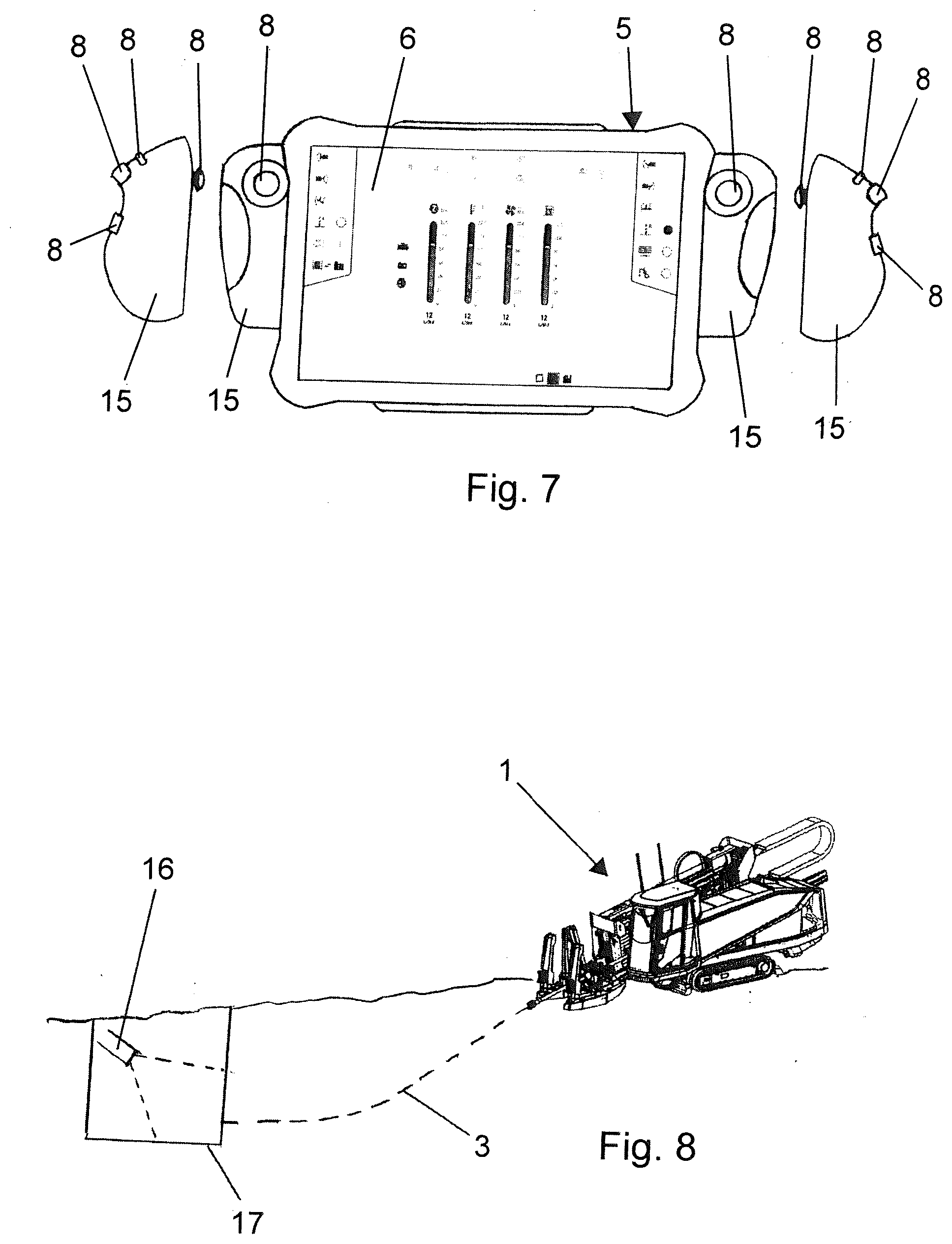
[0068] In one preferred embodiment, a detection device is provided, which is adapted to detecting the drill string at its end side (a) in the area of the ground drilling device and/or (b) in the area of a target pit of an earth borehole being created, and the detection device comprises transmission means which are designed to send signals to the indicator device and/or to the control device, wherein the indicator device and/or the control device are designed to process the signals of the detection device such that the signals are presented on the indicator device for a user. In this way, an area can be detected where usually a (further) operator is assigned to monitor the operation of the ground drilling device. The operator who is controlling the operation of the ground drilling device by means of the input device is shown information thanks to the detection and the presentation of the detection on the indicator device. In this way, the operator who is controlling the operation of the ground drilling device by means of the input device can be shown the corresponding end region of the drill string in terms of the corresponding detection regardless of the position of the operator. It can be provided that it is not necessary for the operator to be present in the corresponding end region of the drill string itself. The signal of the detection device can be utilized. A further added value can thus be achieved, since an additional operator to perform the earth drilling is unnecessary and they may be given other tasks.
[0069] A "detection device" in the sense of the specification encompasses any device which is designed to detect the presence of a drill string, particularly an end of a drill string or a rod section or a drilling head in an area. The detection device may be designed as a device which ascertains a change in the presence of the end of a drill string or a rod section or a drilling head.
[0070] In one preferred embodiment, the detection device is a camera, a zone scanner and/or a motion scanner, whereby it is possible to use known devices whose handling and use--albeit for other fields--are customary.
[0071] In the sense of the specification, a camera is any device which takes a picture of an area that can be displayed in particular on the indicator device. The indicator device can display the signals or information of the camera at least on a portion of the indicator device for this. The signals may be represented directly or be processed prior to the presentation by the control unit of the indicator device and/or the control device of the ground drilling device.
[0072] In the sense of the specification, a zone scanner is a device which can ascertain and detect a change in a presence in a zone. The zone scanner may be designed as a light barrier, light curtain, or the like. The zone scanner may be designed to use ultrasound, electromagnetic radiation in the infrared region, or radar waves.
[0073] In the sense of the specification, a motion scanner is a device which can ascertain and detect a movement in a zone.
[0074] Both the zone scanner and the motion scanner may be used in such a way that, when a movement in any form has been detected, a message is sent to the indicator device. It may also be provided that a signal of a zone scanner or motion scanner is relayed to the input device and a triggering of the zone scanner and/or motion scanner is indicated on a status display of the input device. It may also be provided that as soon as the zone scanner and/or motion scanner is triggered, a picture of a camera is presented on the indicator device, so that the displaying of a picture of a camera which may be present is done only if the zone scanner and/or motion scanner have ascertained a change or a presence of an end of the drill string or rod section or the drilling head.
[0075] The invention also creates a method for controlling the operation of a ground drilling device. The method involves the step of entering at least one parameter for the operation of the ground drilling device. The parameter may be in particular a parameter bringing about a starting of the drilling with the ground drilling device or a stopping of the drilling performed with the ground drilling device. In the method, the entering of the at least one parameter is done by means of a remote control.
[0076] The invention also creates a use of a ground drilling device, having a control device for the operating of the ground drilling device. An input device functionally coupled to the control device is used for entering at least one parameter for the operation of the ground drilling device. The at least one parameter may be in particular a parameter bringing about a starting of the drilling with the ground drilling device or a stopping of the drilling performed with the ground drilling device. A remote control is used as the input device.
[0077] The invention is being described in regard to three aspects, relating to a system, a method, and a use. The remarks on the individual aspects complement each other, so that the remarks for the system should also be understood as remarks describing the method and the use. With the description of the system, actions in regard to the method or method steps concerning the method and uses or usage features are also disclosed, applicable to the corresponding aspects.
[0078] In the sense of the specification, the indication of a numerical value, particularly a length or an angle, encompasses not only the actual numerical value, but also a range about the specific numerical value which may be +/-15%, preferably +/-10%, of the indicated numerical value--in order to allow for fabrication tolerances, in particular.
[0079] The preceding remarks, just as the following description of exemplary embodiments, do not constitute any abandonment of particular embodiments or features.
BRIEF DESCRIPTION OF THE DRAWINGS
[0080] The invention shall now be explained more closely with the aid of an exemplary embodiment presented in the drawing.
[0081] The drawings show:
[0082] FIG. 1a schematic representation of a ground drilling device with a data entry device;
[0083] FIG. 2a schematic representation of the input device and the indicator device;
[0084] FIG. 3a further representation of the input device with the indicator device from above;
[0085] FIG. 4 the input device with the indicator device from below;
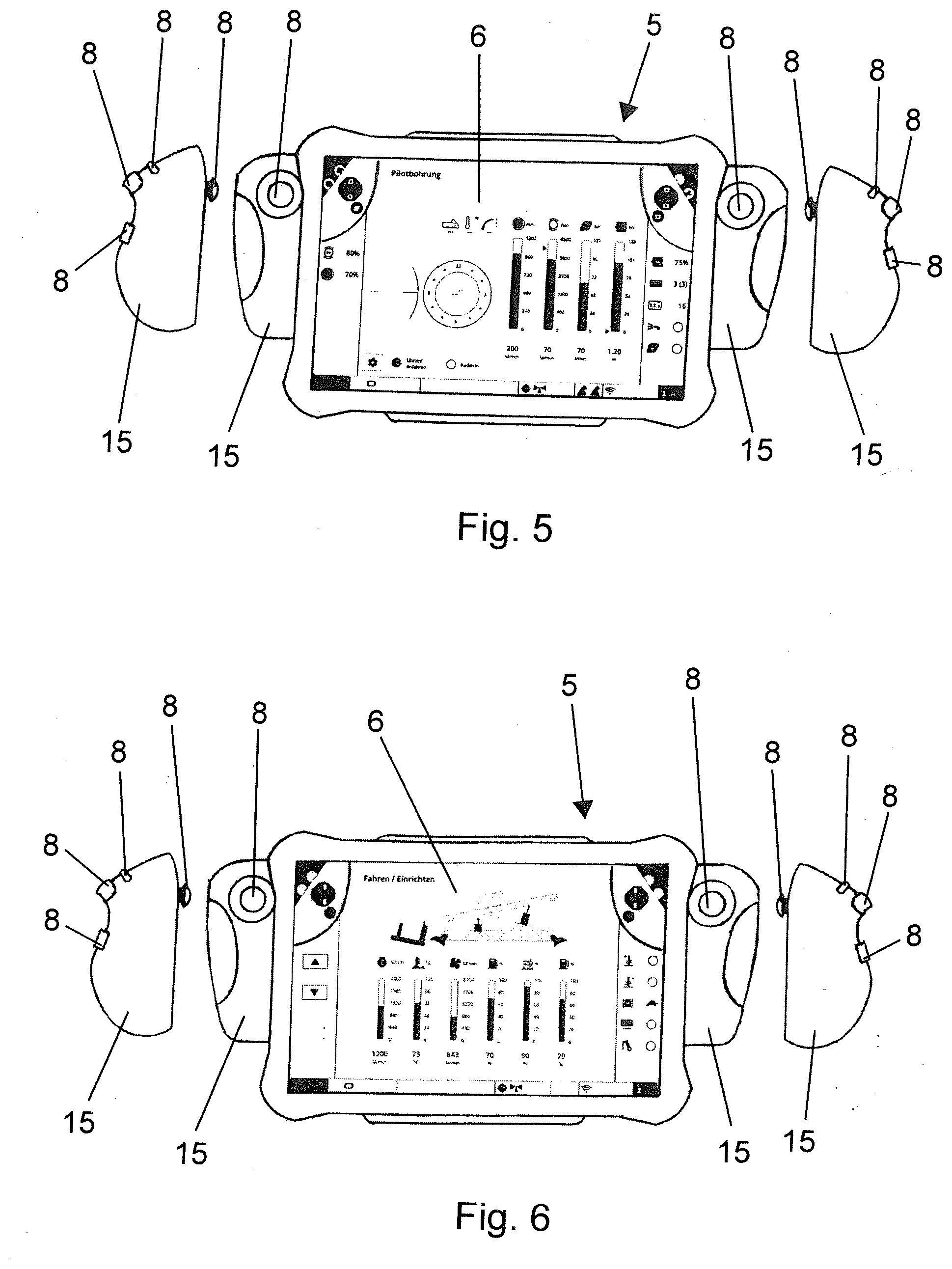
[0086] FIG. 5a representation of the input device with the indicator device in operation;
[0087] FIG. 6a further representation of the input device and the indicator device in operation;
[0088] FIG. 7a further representation of the input device with the indicator device in operation; and
[0089] FIG. 8a schematic representation of one embodiment in which the end region of the drill string is monitored in the region of the ground drilling device and a target pit.
DETAILED DESCRIPTION
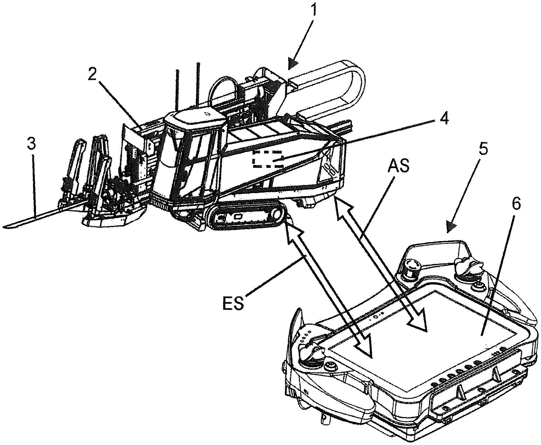
[0090] FIG. 1 shows in a schematic representation a ground drilling device 1 with which an earth borehole can be made in the soil. Rod sections are stored in a string magazine 2, with which the drill string 3 already introduced into the soil can be lengthened.
[0091] The ground drilling device 1 comprises a control device 4 for operating the ground drilling device 1, being shown schematically by means of the box in broken lines. The operation of the ground drilling device 1 can be controlled by means of the control device 4.
[0092] Moreover, there is present an input device 5, functionally coupled to the control device 4, being adapted to enter at least one parameter for the operation of the ground drilling device 1. In particular, such a parameter may be a starting of the drilling with the ground drilling device 1 or a stopping of a drilling performed with the ground drilling device 1. The input device 5 is configured as a remote control, which communicates in wireless manner with the control device 4 by means of electromagnetic waves.
[0093] The wireless communication between the input device 5 and the control device 4 is a bidirectional communication, in which the input device 5 both receives signals from the control device 4 and sends to the control device 4. The bidirectional wireless communication is indicated by means of the double arrow ES.
[0094] Moreover, an indicator device 6 is provided, with which information and/or parameters for the operation of the ground drilling device 1 can be represented. For the representation of the information and parameters, the indicator device 6 is functionally coupled to the control device 4. The communication between the indicator device 6 and the control device 4 is wireless by means of electromagnetic waves. The communication is bidirectional, so that the indicator device 6 can both receive signals from the control device 4 and send to the control device 4. The bidirectional communication is indicated by means of the double arrow AS.
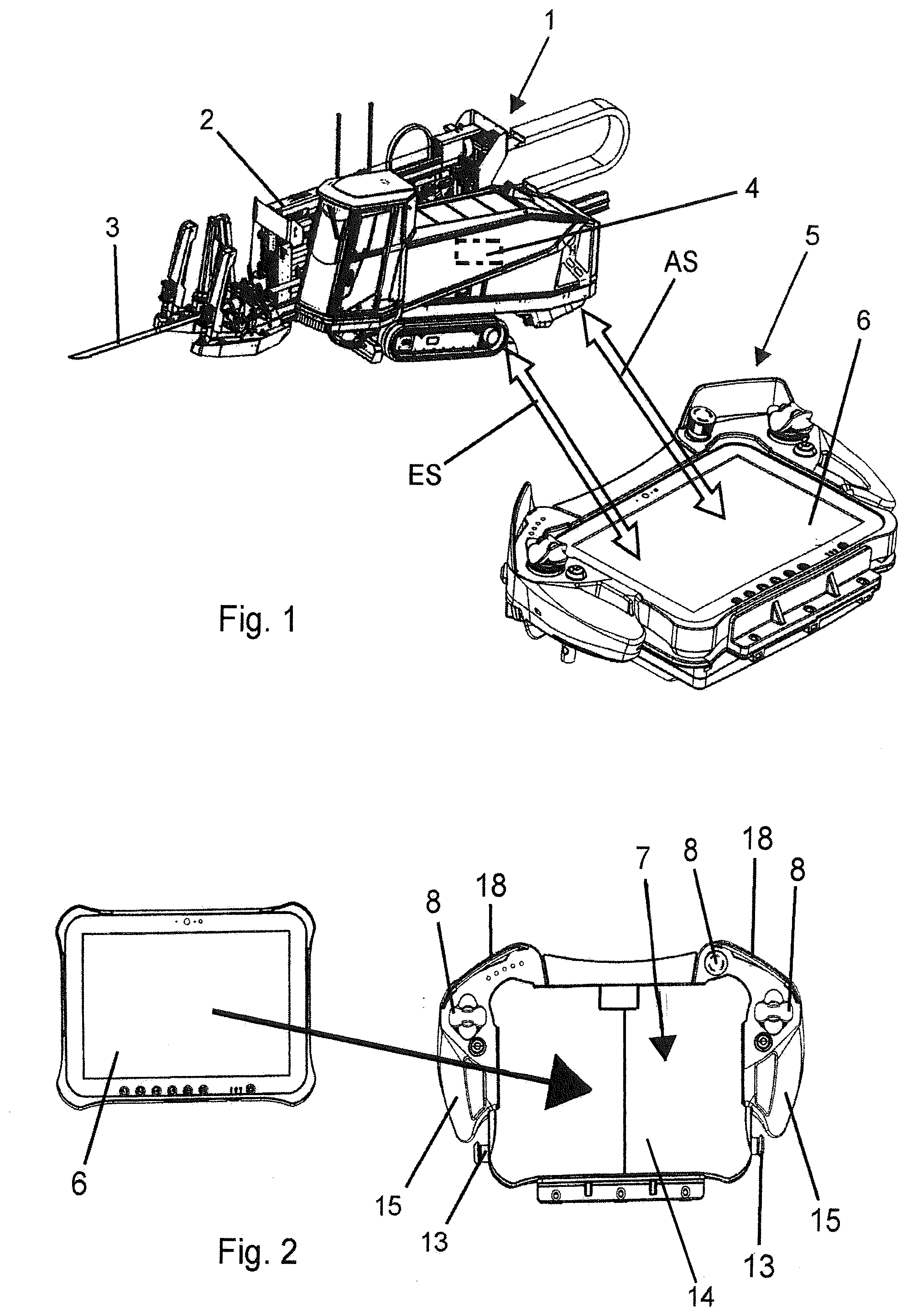
[0095] As can be seen from FIG. 2, the indicator device 6 can be arranged in a holder 7 of the input device 5 so that the indicator device 6 can be manipulated together with the input device 5 as a unit by an operator.
[0096] The input device 5 comprises multiple mechanically operated activating elements 8, two of which are configured as control sticks. Moreover, the input device 5 comprises an emergency off switch 9 as a mechanically operated activating element 8, being configured as a pushbutton. The activating elements 8 configured as control sticks and the emergency off switch 9 are facing toward an operator when the input device 5 is held and are located in a plane of the input device 5. Situated opposite the surface on which the control sticks and the emergency off switch 9 are arranged, two rotary switches are formed as mechanically operated activating elements 8 at the left and right of the input device 5.
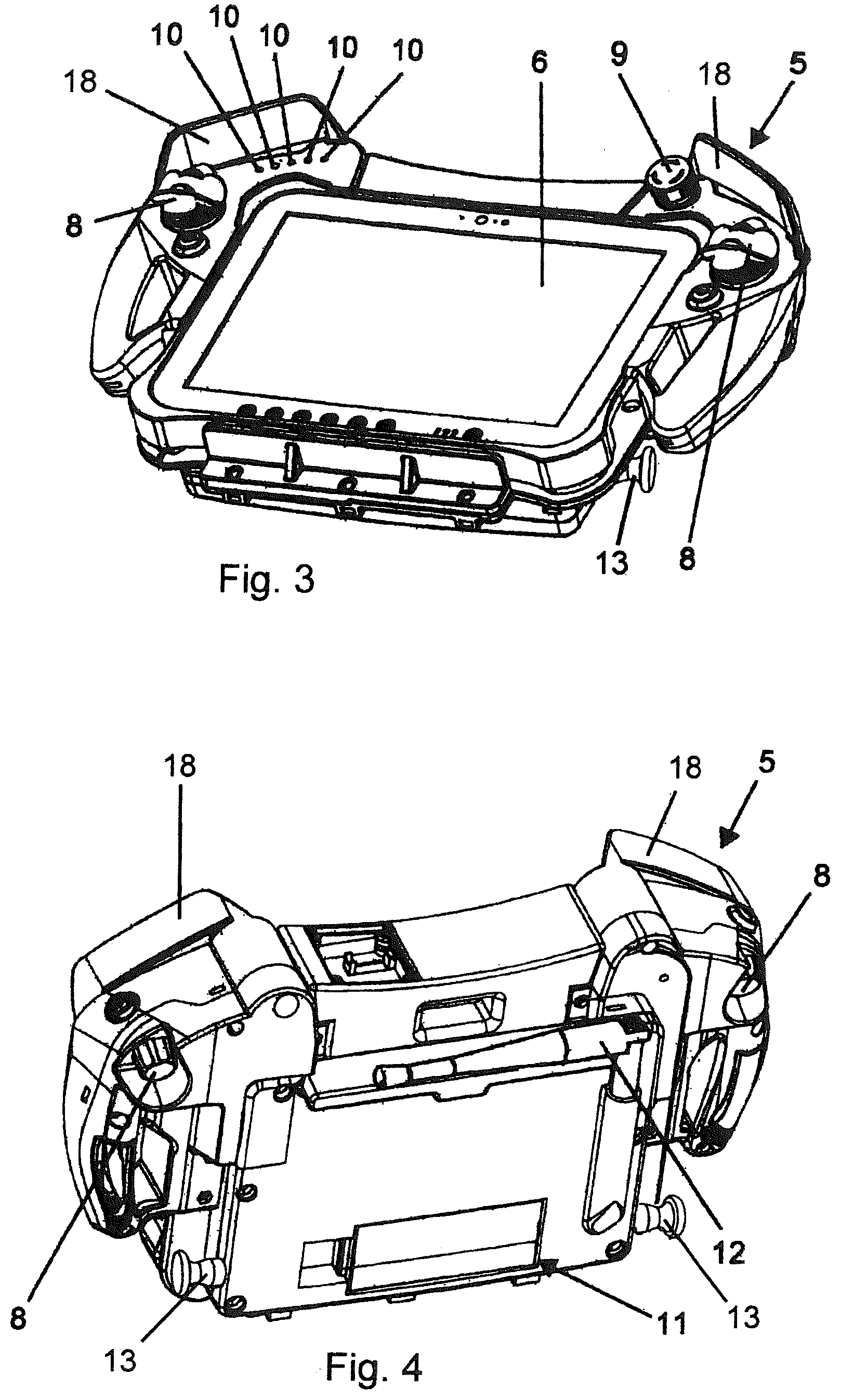
[0097] On the left side of the input device 5 there are provided multiple status displays 10 providing information as to the status of the input device 5, the ground drilling device 1 and/or a communication between the input device 5 and the control device 4.
[0098] Moreover, the input device 5 has a receiving space 11 for a power supply of the input device 5, designed as a compartment on the underside of the input device 5.
[0099] A swiveling antenna 12 is present for the wireless communication with the control device 4, which can swivel in regard to its orientation and is telescopically adjustable in length.
[0100] A protective shield 18 is formed on the input device 5 to protect the activation of the mechanically operated activating elements 8, being situated in the area of the emergency off switch 9 and the control stick.
[0101] Connection elements 13 are provided for the attachment of a neck, shoulder, or waist strap, to which the corresponding strap can be connected.
[0102] The input device 5 comprises a base plate 14 to hold the indicator device 6, being substantially rectangular in shape (see FIG. 1). The mechanically operated activating elements 8 are formed in handle-shaped protrusions 15 of the base plate 14, each of them being graspable by the hand of the operator in order to carry out the operation. The protrusions 15 extend in an upward direction, and form an edge around the base plate 14. The protrusions 15 each form an edge on one side. The two edges which are formed by the protrusions 15 lie opposite each other. On the other two sides of the rectangular base plate 14 there are other marginal segments extending upward in the same direction as the edges formed by the protrusions 15. In this way, an edge is created which surrounds the base plate 14 at least partly, in which the indicator device 6 can be arranged. A force locking can be formed, with the indicator device 6 engaging at least partly behind the protrusions 15 at the edges formed by the protrusions 15.
[0103] FIG. 5 to 7 show another embodiment of the input device 5 with the indicator device 6 of FIGS. 2 to 4. The protrusions 15 of the input device 5 in this case are not designed as handles which can be grasped by hand. The representations at left and right of FIGS. 5 to 7 show the area of the protrusions 15 from the side. There are present a control stick at the top, a forward pointing rotary switch, and two pushbuttons as the mechanically operated activating elements 8 for each protrusion 15.
[0104] FIG. 8 shows a system with a detection device 16 designed as a camera, being adapted to detect the drill string 3 at its end in the area of a target pit 17 for an earth borehole being produced. The detection device 16 comprises transmission means which are adapted to send signals to the indicator device 6 and to the control device 4. The signals can be represented on the indicator device 6, in particular, a picture taken by the camera can be represented on the indicator device 6.
* * * * *
D00000
D00001
D00002
D00003
D00004
XML
uspto.report is an independent third-party trademark research tool that is not affiliated, endorsed, or sponsored by the United States Patent and Trademark Office (USPTO) or any other governmental organization. The information provided by uspto.report is based on publicly available data at the time of writing and is intended for informational purposes only.
While we strive to provide accurate and up-to-date information, we do not guarantee the accuracy, completeness, reliability, or suitability of the information displayed on this site. The use of this site is at your own risk. Any reliance you place on such information is therefore strictly at your own risk.
All official trademark data, including owner information, should be verified by visiting the official USPTO website at www.uspto.gov. This site is not intended to replace professional legal advice and should not be used as a substitute for consulting with a legal professional who is knowledgeable about trademark law.