LASER INDUCED, FINE GRAINED, GAMMA PHASE SURFACE FOR NiCoCrAlY COATINGS PRIOR TO CERAMIC COAT
Thayer; Henry H. ; et al.
U.S. patent application number 16/353490 was filed with the patent office on 2020-09-17 for laser induced, fine grained, gamma phase surface for nicocraly coatings prior to ceramic coat. This patent application is currently assigned to United Technologies Corporation. The applicant listed for this patent is United Technologies Corporation. Invention is credited to David Ulrich Furrer, Dmitri Novikov, Henry H. Thayer.
| Application Number | 20200291529 16/353490 |
| Document ID | / |
| Family ID | 1000004748607 |
| Filed Date | 2020-09-17 |

| United States Patent Application | 20200291529 |
| Kind Code | A1 |
| Thayer; Henry H. ; et al. | September 17, 2020 |
LASER INDUCED, FINE GRAINED, GAMMA PHASE SURFACE FOR NiCoCrAlY COATINGS PRIOR TO CERAMIC COAT
Abstract
A process for forming a thermal barrier coating on a part comprising depositing an aluminum containing bond coat on the part, the bond coat comprising a surface; cleaning the surface to remove oxides and debris from the surface of the bond coat; forming a gamma phase layer proximate the surface of the bond coat; forming an aluminum oxide layer on the surface of the bond coat; and depositing a ceramic topcoat on the aluminum oxide layer on the bond coat.
| Inventors: | Thayer; Henry H.; (Wethersfield, CT) ; Novikov; Dmitri; (Avon, CT) ; Furrer; David Ulrich; (Marlborough, CT) | ||||||||||
| Applicant: |
|
||||||||||
|---|---|---|---|---|---|---|---|---|---|---|---|
| Assignee: | United Technologies
Corporation Farmington CT |
||||||||||
| Family ID: | 1000004748607 | ||||||||||
| Appl. No.: | 16/353490 | ||||||||||
| Filed: | March 14, 2019 |
| Current U.S. Class: | 1/1 |
| Current CPC Class: | C23C 28/3455 20130101 |
| International Class: | C23C 28/00 20060101 C23C028/00 |
Claims
1. A process for forming a thermal barrier coating on a part comprising: depositing an aluminum containing bond coat on the part, said bond coat comprising a surface; cleaning said surface to remove oxides and debris from the surface of the bond coat; forming a gamma phase layer proximate the surface of the bond coat; forming an aluminum oxide layer on said surface of said bond coat; and depositing a ceramic topcoat on the aluminum oxide layer on the bond coat.
2. The process according to claim 1, wherein said cleaning comprises exposing the surface to an energy beam focused on the surface of the bond coat and forming a liquid from the bond coat proximate the surface.
3. The process according to claim 2, further comprising: rapidly cooling the liquid into said gamma phase layer; and forming an alpha aluminum oxide proximate said surface.
4. The process according to claim 2, wherein said energy beam produces high intensity, short duration energy beam pulses.
5. The process according to claim 1, further comprising: inhibiting a non-alpha aluminum oxide layer from growing responsive to said gamma phase layer proximate said surface.
6. The process according to claim 1, further comprising: distributing the aluminum in the bond coat uniformly, so that the alpha aluminum oxide layer is even and has reduced internal stresses.
7. The process according to claim 1, wherein said gamma phase layer proximate the surface comprises a supersaturated aluminum content and low aluminum diffusivity properties.
8. The process according to claim 1, further comprising: growing an initial alpha-alumina scale during the cleaning step.
9. The process according to claim 1, wherein the gamma phase layer comprises a thickness of about 1.5 microns.
10. The process according to claim 1, wherein said gamma phase layer proximate the surface of the bond coat is an aluminum diffusion inhibitor.
11. The process according to claim 8, wherein said gamma phase layer impedes fast aluminum oxidation at the surface.
12. The process according to claim 8, wherein the gamma phase layer allows for a very thin initial alpha-alumina scale to grow during said cleaning step.
Description
BACKGROUND
[0001] The present disclosure is directed to a thermal barrier coating system for a component that is exposed to high temperatures, such as a gas turbine engine component (e.g. blades, vanes, etc.). More particularly, the present invention relates to the formation of a thermal barrier coating system and a method of forming a thermal barrier coating on a metal part that includes laser cleaning a surface of the metal part to remove undesirable oxides and residues from the surface of the part.
[0002] A gas turbine engine component, such as a blade tip, blade trailing edge, blade platform, blade airfoil, vane airfoil, vane trailing edge, or vane platform, is typically exposed to a high temperature and high stress environment. The high temperature environment may be especially problematic with a superalloy component. Namely, the high temperatures may cause the superalloy to oxidize, or weaken which then decreases the life of the component. In order to extend the life of the component, a thermal barrier coating system (TBC system) may be applied to the entire superalloy component or selective surfaces, such as surfaces of the superalloy component that are exposed to the high temperatures and other harsh operating conditions. A TBC system protects the underlying material (also generally called the "substrate") and helps inhibit oxidation, corrosion, erosion, and other environmental damage to the substrate. Desirable properties of a TBC system include low thermal conductivity and strong adherence to the underlying substrate.
[0003] The TBC system includes a metallic bondcoat or oxidation resistant coating and a ceramic topcoat (i.e., a thermal barrier coating or TBC topcoat). The bondcoat is applied to the substrate and aids the growth of a thermally grown oxide (TGO) layer, which is typically alpha aluminum oxide, (Al.sub.2O.sub.3 or "alumina"). Specifically, prior to or during deposition of the TBC topcoat on the bondcoat, the exposed surface of the bondcoat can be oxidized to form the alumina TGO layer or scale. The TGO forms a strong bond to both the topcoat and the bondcoat, and as a result, the TGO layer helps the TBC topcoat adhere to the bondcoat. The bond between the TGO and the topcoat is typically stronger than the bond that would form directly between the TBC topcoat and the bondcoat. The TGO also acts as an oxidation resistant layer, or an "oxidation barrier", to help protect the underlying substrate from damage due to oxidation.
[0004] In order for the TBC layer to adhere to the metallic bond coat (BC) (NiCoCrAlY for example), an oxide intermediate layer, a thermally grown oxide (TGO) is needed. Bond coat alloy in equilibrium consists of Aluminum (Al) poor phase ("gamma" phase, face centered cubic (fcc) crystal structure) and Al rich phase ("beta" phase, body centered cubic (bcc) crystal structure).
[0005] It should be noted that self-diffusion coefficient in bcc "beta" phase is by order of magnitude higher than the one in fcc "gamma" phase due to its lower packing factor and lower coordination number.
[0006] Although the TGO is needed to bond the TBC to the metallic coat, the TGO continues to grow as the engine runs. The slight mismatch in volume between the TGO and TBC causes a build-up of stress between them that eventually causes the coating to fail. Therefore, it is important to have the thinnest TGO possible at the start of the process, and to slow the growth of the TGO during engine run conditions.
SUMMARY
[0007] In accordance with the present disclosure, there is provided a process for forming a thermal barrier coating on a part comprising depositing an aluminum containing bond coat on the part, the bond coat comprising a surface; cleaning the surface to remove oxides and debris from the surface of the bond coat; forming a gamma phase layer proximate the surface of the bond coat; forming an aluminum oxide layer on the surface of the bond coat; and depositing a ceramic topcoat on the aluminum oxide layer on the bond coat.
[0008] In another and alternative embodiment, the cleaning comprises exposing the surface to an energy beam focused on the surface of the bond coat and forming a liquid from the bond coat proximate the surface.
[0009] In another and alternative embodiment, the process further comprises rapidly cooling the liquid into the gamma phase layer, and forming an alpha aluminum oxide proximate the surface.
[0010] In another and alternative embodiment, the energy beam produces high intensity, short duration energy beam pulses.
[0011] In another and alternative embodiment, the process further comprises inhibiting a non-alpha aluminum oxide layer from growing responsive to the gamma phase layer proximate the surface.
[0012] In another and alternative embodiment, the process further comprises distributing the aluminum in the bond coat uniformly, so that the alpha aluminum oxide layer is even and has reduced internal stresses.
[0013] In another and alternative embodiment, the gamma phase layer proximate the surface comprises a supersaturated aluminum content and low aluminum diffusivity properties.
[0014] In another and alternative embodiment, the process further comprises growing an initial alpha-alumina scale during the cleaning step.
[0015] In another and alternative embodiment, the gamma phase layer comprises a thickness of about 1.5 microns.
[0016] In another and alternative embodiment, the gamma phase layer proximate the surface of the bond coat is an aluminum diffusion inhibitor.
[0017] In another and alternative embodiment, the gamma phase layer impedes fast aluminum oxidation at the surface.
[0018] In another and alternative embodiment, the gamma phase layer allows for a very thin initial alpha-alumina scale to grow during the cleaning step.
[0019] Other details of the process are set forth in the following detailed description and the accompanying drawings wherein like reference numerals depict like elements.
BRIEF DESCRIPTION OF THE DRAWINGS
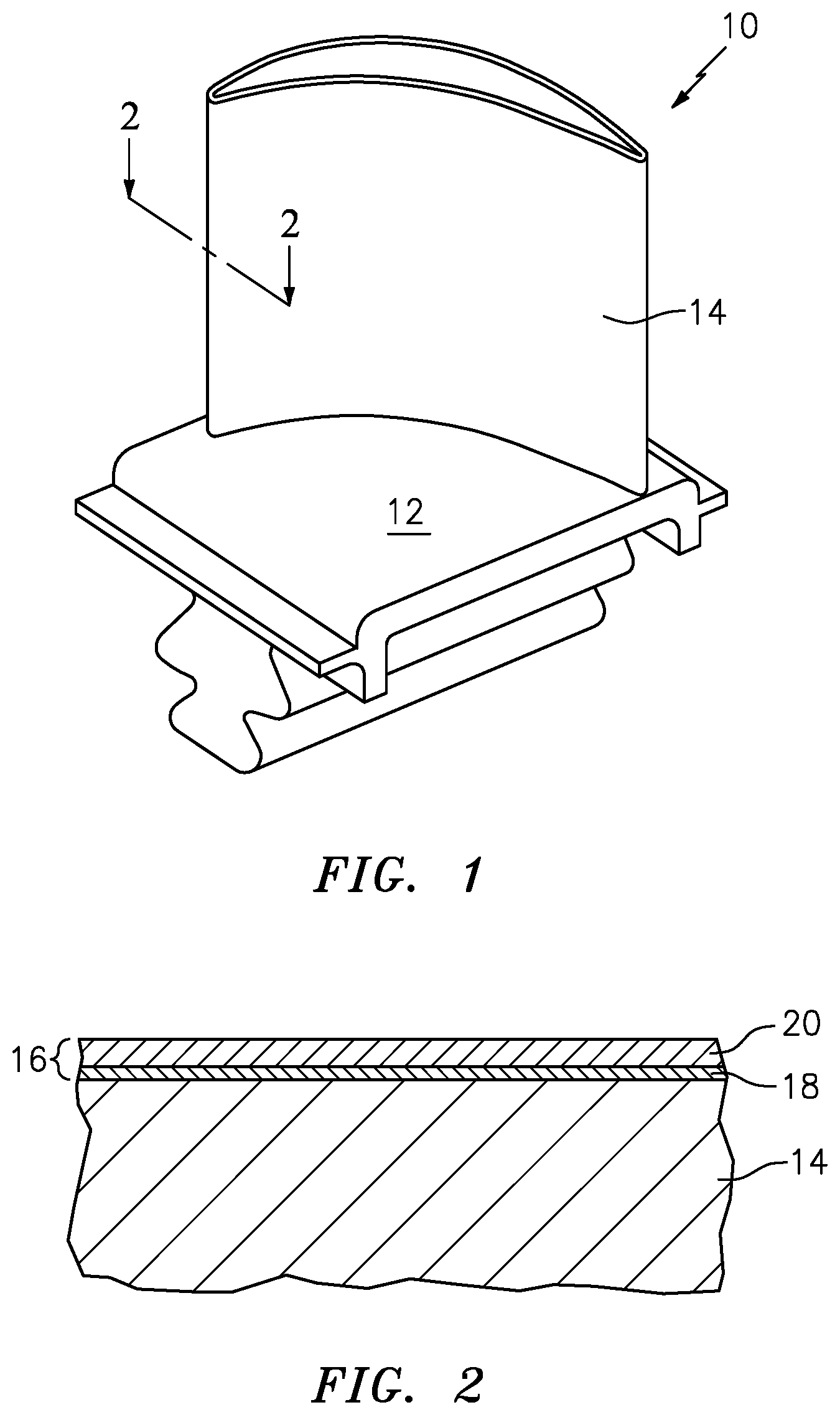
[0020] FIG. 1 is a perspective view of a turbine blade.
[0021] FIG. 2 is a cross-sectional view of the turbine blade of FIG. 1 where a section has been taken at line 2-2 (shown in FIG. 1) and show a thermal barrier coating system overlying the airfoil of the turbine blade.
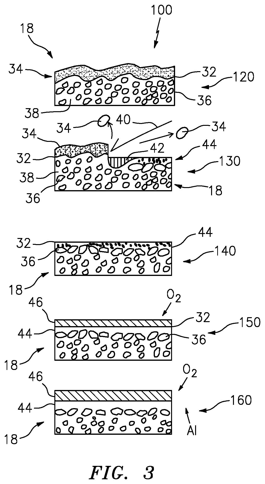
[0022] FIG. 3 is an exemplary cleaning process.
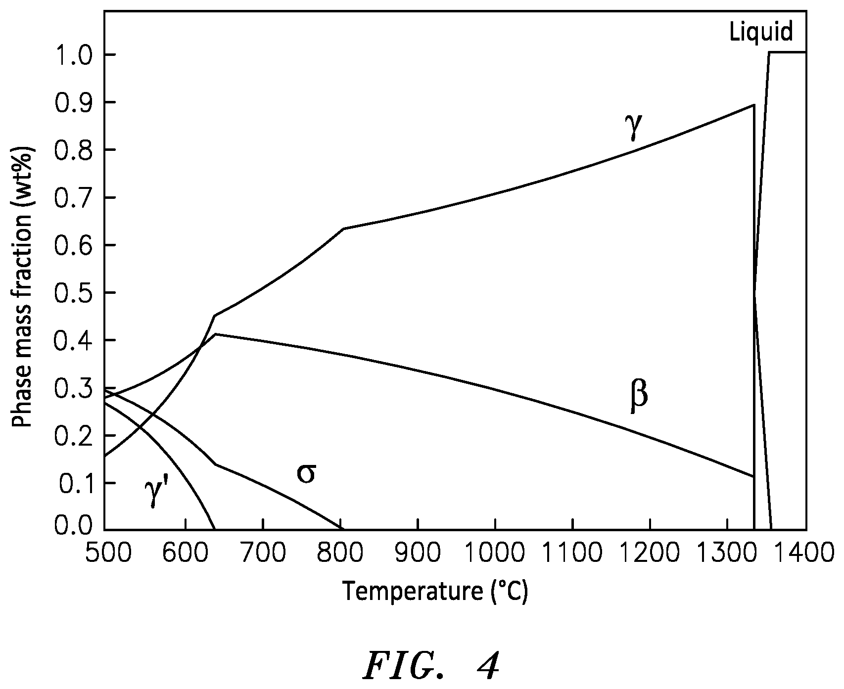
[0023] FIG. 4 is a phase diagram of an exemplary bond coat as a function of temperature.
DETAILED DESCRIPTION
[0024] FIG. 1 is a perspective view of turbine blade 10 of a gas turbine engine. Turbine blade 10 includes platform 12 and airfoil 14. Airfoil 14 of turbine blade 10 may be formed of a nickel based, cobalt based, iron based superalloy, or mixtures thereof or a titanium alloy. Turbine blade 10 is exposed to high temperatures and high pressures during operation of the gas turbine engine. In order to extend the life of turbine blade 10 and protect it from high stress operating conditions and the potential for oxidation and corrosion, a thermal barrier coating (TBC) (shown in FIG. 2) is applied over airfoil 14 and platform 12 of turbine blade 10.
[0025] The exact placement of the TBC system depends on many factors, including the type of turbine blade 10 employed and the areas of turbine blade 10 exposed to the most stressful conditions. For example, in alternate embodiments, a TBC may be applied over a part of the outer surface of airfoil 14 rather than over the entire surface of airfoil 14. Airfoil 14 may include cooling holes leading from internal cooling passages to the outer surface of airfoil 14, and the system 16 may also be applied to the surface of the cooling holes.
[0026] FIG. 2 is a sectional view of turbine blade 10, where a section is taken from line 2-2 in FIG. 1. TBC system 16 is applied to an exterior surface of airfoil 14 and platform 12.
[0027] TBC system 16 may include bondcoat 18 and ceramic layer 20. Bond coat 18 overlays and bonds to airfoil 14 and platform 12 while ceramic layer 20 overlays and bonds to the thermally grown oxide (TGO) on the bond coat 18. In the embodiment shown in FIG. 2, bond coat 18 may be applied to airfoil 14 and platform 12 at a thickness ranging from about 0.5 mils (0.0127 mm) to about 10 mils (0.254 mm). Ceramic layer 20 may be any thermal barrier coating (or "topcoat") that is suitable for use on alumina forming bond coats and/or alloys. Non-limiting examples include zirconia stabilized with yttria (Y.sub.2O.sub.3), gadolinia (Gd.sub.3O.sub.3), ceria (CeO.sub.2), scandia (Sc.sub.2O.sub.3), and other oxides known in the art. Ceramic layer 20 may be applied by electron beam physical vapor deposition (EBPVD) or by plasma spray. Ceramic layer 20 may be deposited in thickness sufficient enough to provide the required thermal protection for bondcoat 18 and substrate 10.
[0028] Bond coat 18 may be a MCrAlY coating where M may be Ni, Co, Fe, Pt, Ni-base alloy, Co-base alloy, Fe-base alloy or mixtures thereof. In an embodiment, M may include Hf or Si or mixtures thereof. In an exemplary embodiment, the bond coat 18 can comprise NiCoCrAlY. Bond coat 18 may be applied to airfoil 14 and platform 12 by any suitable technique including, but not limited to, thermal spray processes such as low pressure plasma spray (LPPS) deposition and high velocity oxyfuel (HVOF) deposition, physical vapor deposition such as cathodic arc deposition or chemical vapor deposition, and the like. In an embodiment, bond coat 18 may be an aluminide bondcoat formed by techniques such as pack cementation, chemical vapor deposition, and others followed by appropriate diffusion heat treatments.
[0029] The process 100 can be understood by referring also to FIG. 3. At an initial state 120, the bondcoat 18 includes a surface 32 covered with contaminant materials 34, such as oils, oxides and the like. Within the bond coat 18, a combination of beta phase bcc structure 36 and gamma phase fcc structure 38 is shown distributed throughout the bond coat 18. The beta phase bcc structure 36 can act as an Al reservoir for the bond coat 18. The gamma phase fcc structure 38 can act as an Al diffusion media.
[0030] At step 130 cleaning and structural refinement takes place at and near the surface 32 of the bond coat 18. The cleaning is done at high temperature and at an atmospheric pressure. In an exemplary embodiment, the cleaning temperature can be above 1350 degrees C., the point at which the NiCoCrAlY liquefies. An energy beam 40 is utilized to remove the contaminants 34 while also melting the bond coat 18 proximate the surface 32, forming a liquid 42 from the bond coat 18 material. The liquid 42 subsequently rapidly cools down into a fine grained layer 44. The grain refinement is achieved by very rapid melting and re-solidification of the bond coat 18 material at the surface 32 under very high intensity, short duration energy beam pulses. In an exemplary embodiment, the energy beam 40 can utilize a 50-100 nano-second pulse duration at 5-50 J/cm{circumflex over ( )}2. The local surface 32 heating above the predetermined temperature, such as 1350 degrees Centigrade, can create the fine grained predominantly gamma phase layer 44 proximate the surface 32. Raising the temperature this way causes the metal right at the surface to liquefy very quickly, and re-solidify very quickly providing the desired fine grain structure.
[0031] The energy beam 40 can include a laser. The laser can include an yttrium aluminum garnet laser, ultraviolet, eximer, or carbon dioxide, fiber, or disc laser. The laser can have a power range up to about 1000 watts.
[0032] The surface environment during the cleaning portion 130, can include air, inert gas, water, or combinations thereof.
[0033] In an exemplary embodiment, a laser based cleaning system for removing contaminants from the surface 32 may include: a laser 40 capable of removing the oxide layer and producing an aluminum oxide layer on the substrate surface 32; an optical system capable of focusing the laser at the oxide layer; and a scanning system capable of directing the focused laser beam over the surface 32 to remove contaminants to produce the gamma phase layer 44 on the substrate 32.
[0034] In an exemplary embodiment, the Al-rich gamma phase layer 44 can be about 0.5 microns. In an exemplary embodiment the gamma phase layer 44 can range from about 0.25 microns to about 0.75 microns. In another exemplary embodiment, the gamma phase layer 44 can be about 1.5 microns thick. The thickness of the layer 44 can be controlled by the amount of energy beam applied power to the surface 32. In an exemplary embodiment, the energy beam 40 applied power can range from about 500 Watts to about 1000 Watts. In an exemplary embodiment, the surface 32 can be heated to about 1350 degrees C. The surface 32 can be heated to temperatures from about 1350 degrees C. possibly much hotter, but not so hot as to start boiling off the Aluminum, so 2470 degrees C. would be the upper limit to produce the desired gamma phase layer 44. At the higher temperatures, as can be seen at FIG. 4, the bond coat 18 is converted predominantly to gamma phase.
[0035] At 140 it can be seen that after cleaning and structural refinement, the bond coat 18 includes the gamma phase layer 44 with a smooth surface 32. The elements proximate the surface 32 of the metallic bond coat 18 tend to be Ni and Al. The molten alloy 42 freezes first at the location where it is in contact with the bulk of the solid bond coat 18 and freezes last where the molten alloy 42 is in contact with air or process gases. Thus, the disclosed process promotes gamma-alumina formation proximate the surface 32. Under ambient conditions, the gamma phase normally has lower Al content than the beta phase. However, because of the rapid melting and refreezing caused by the energy beam 40, all of the Al is still present, so the gamma phase layer 44 is Al rich, or supersaturated with Al. Because the gamma phase is supersaturated with Al (i.e. it wants to get rid of Al) the gamma phase layer 44 has ability to create a dense initial alpha-alumina layer of TGO and avoid the non-alpha phase aluminum.
[0036] The layer 44 is Al oversaturated which can be beneficial for the next step 150 of forming the aluminum oxide layer (TGO) 46 on the surface 32. The extremely fine grain structure 44 distributes the aluminum in the bond coat 18 very uniformly, so that the thermally grown oxide (TGO) 46 is even and has fewer internal stresses.
[0037] At 160, it can be seen that once the thermally grown oxide 46 is formed, the TGO 46 will be inhibited from growing rapidly, and will grow slowly as compared to a surface that was not treated by the disclosed process. The gamma phase 44 proximate the surface is reduced in aluminum content and has poor diffusivity properties for aluminum. The slower TGO 46 growth will result in good adhesion between the TBC 20 and the metallic bond coat 18. This also provides the benefit of longer life adhesion of the TBC 20, because the TGO 46 thickness is smaller and the stresses between the TGO 46 and TBC 20 will grow more slowly. The uniform gamma like fcc phase has an order of magnitude lower self-diffusion coefficient that the beta bcc phase material. The gamma phase 44 impedes fast Al oxidation at the surface 32, and allows for a very thin initial alpha-alumina scale to grow during the disclosed laser cleaning process. The rapid cooling and formation of the gamma phase layer inhibits a non-alpha aluminum oxide layer from growing responsive to said gamma phase layer proximate said surface. The non-alpha aluminum oxides can include aluminum oxide in other phases, including the cubic .gamma. and .eta. phases, the monoclinic .theta. phase, the hexagonal .chi. phase, the orthorhombic .kappa. phase and the .delta. phase that can be tetragonal or orthorhombic. The aluminum oversaturation ensures that aluminum oxides are preferentially created proximate the surface 32. During subsequent TGO 46 growth in an EB-PVD chamber that initial alpha-alumina creates conditions for preferential alpha-alumina growth, which is less prone to further oxygen diffusion that causes TGO growth during part service life. TBC spallation happens when the TGO thickness reaches a certain value. The disclosed process provides for the initial TGO thickness and TGO growth rate coefficient to be smaller. The TGO growth coefficient for laser cleaned sample is about 2 times smaller than that for a grit blasted one.
[0038] The disclosed process relies upon surface chemical/phase composition modifications of the bond coat. In an exemplary embodiment, further protection can include adding other alloying elements to the bond coat surface 32, such as Pt, to further impeded the TGO growth.
[0039] The technical benefits of utilizing the disclosed process includes optimized surface chemistry for optimal TGO growth.
[0040] Another technical advantage of the disclosed process is the development of a smooth surface 32 without steps and ledges that mitigates geometric stress build-up.
[0041] Another technical advantage of the disclosed process is that surface treated material is given a diffusion barrier and controller for aluminum so that the TGO starts and continues to grow uniformly with a smooth, non-stepped geometry.
[0042] Another technical advantage of the disclosed process is that surface treating with a laser or other energy source (like e-beam) is a preferred approach.
[0043] Another technical advantage of the disclosed process can include adding supplemental elements to the surface by pre-coating (vapor deposition, sputtering, etc.) followed by laser processing that can also provide optimal surface material for TGO growth and subsequent diffusion barrier/control.
[0044] There has been provided a process. While the process has been described in the context of specific embodiments thereof, other unforeseen alternatives, modifications, and variations may become apparent to those skilled in the art having read the foregoing description. Accordingly, it is intended to embrace those alternatives, modifications, and variations which fall within the broad scope of the appended claims.
* * * * *
D00000
D00001
D00002
D00003
XML
uspto.report is an independent third-party trademark research tool that is not affiliated, endorsed, or sponsored by the United States Patent and Trademark Office (USPTO) or any other governmental organization. The information provided by uspto.report is based on publicly available data at the time of writing and is intended for informational purposes only.
While we strive to provide accurate and up-to-date information, we do not guarantee the accuracy, completeness, reliability, or suitability of the information displayed on this site. The use of this site is at your own risk. Any reliance you place on such information is therefore strictly at your own risk.
All official trademark data, including owner information, should be verified by visiting the official USPTO website at www.uspto.gov. This site is not intended to replace professional legal advice and should not be used as a substitute for consulting with a legal professional who is knowledgeable about trademark law.