System For Mobile Robot To Autonomously Take Elevator
Deng; Yingcong ; et al.
U.S. patent application number 16/818402 was filed with the patent office on 2020-09-17 for system for mobile robot to autonomously take elevator. This patent application is currently assigned to Tyco Electronics (Shanghai) Co. Ltd.. The applicant listed for this patent is Kunshan Sanxin Plastic Industiry Co. Ltd, TE Connectivity Corporation, Tyco Electronics (Shanghai) Co. Ltd.. Invention is credited to Yingcong Deng, Roberto Francisco-Yi Lu, Mingyang Weng, Fengchun Xie, Dandan Zhang.
| Application Number | 20200290843 16/818402 |
| Document ID | / |
| Family ID | 1000004753142 |
| Filed Date | 2020-09-17 |


| United States Patent Application | 20200290843 |
| Kind Code | A1 |
| Deng; Yingcong ; et al. | September 17, 2020 |
System For Mobile Robot To Autonomously Take Elevator
Abstract
A system for a mobile robot to autonomously take an elevator includes an elevator button pressing module mounted on an elevator floor control panel of the elevator. The elevator button pressing module communicates with the mobile robot wirelessly and is adapted to press a pair of elevator buttons on the elevator floor control panel according to an instruction issued by the mobile robot to call an elevator car.
| Inventors: | Deng; Yingcong; (Shanghai, CN) ; Zhang; Dandan; (Shanghai, CN) ; Lu; Roberto Francisco-Yi; (Bellevue, WA) ; Xie; Fengchun; (Shanghai, CN) ; Weng; Mingyang; (KunShan City, CN) | ||||||||||
| Applicant: |
|
||||||||||
|---|---|---|---|---|---|---|---|---|---|---|---|
| Assignee: | Tyco Electronics (Shanghai) Co.
Ltd. Shanghai PA TE Connectivity Corporation Berwyn Kunshan Sanxin Plastic Industry Co. Ltd KunShan City |
||||||||||
| Family ID: | 1000004753142 | ||||||||||
| Appl. No.: | 16/818402 | ||||||||||
| Filed: | March 13, 2020 |
| Current U.S. Class: | 1/1 |
| Current CPC Class: | B66B 2201/4653 20130101; B66B 1/3461 20130101; B66B 2201/101 20130101; B66B 13/02 20130101; B66B 1/468 20130101; B66B 2201/4638 20130101; B66B 3/002 20130101 |
| International Class: | B66B 1/46 20060101 B66B001/46; B66B 3/00 20060101 B66B003/00; B66B 13/02 20060101 B66B013/02; B66B 1/34 20060101 B66B001/34 |
Foreign Application Data
| Date | Code | Application Number |
|---|---|---|
| Mar 15, 2019 | CN | 201910197908.9 |
Claims
1. A system for a mobile robot to autonomously take an elevator, comprising: an elevator button pressing module mounted on an elevator floor control panel of the elevator, the elevator button pressing module communicates with the mobile robot wirelessly and is adapted to press a pair of elevator buttons on the elevator floor control panel according to an instruction issued by the mobile robot to call an elevator car.
2. The system of claim 1, wherein the elevator button pressing module includes a housing mounted on the elevator floor control panel, the housing having a back side facing the elevator floor control panel and a front side facing away from the elevator floor control panel.
3. The system of claim 2, wherein the elevator button pressing module includes a pair of virtual fingers on the back side of the housing, the virtual fingers are movable relative to the housing.
4. The system of claim 3, wherein the elevator button pressing module includes a driver in the housing driving the virtual fingers to move.
5. The system of claim 4, wherein the elevator button pressing module includes a controller disposed in the housing and controlling the driver, the controller wirelessly communicates with the mobile robot.
6. The system of claim 5, wherein the controller controls the driver according to the instruction issued by the mobile robot, the driver drives one of the virtual fingers to move to press a corresponding one of the elevator buttons on the elevator floor control panel under the control of the controller.
7. The system of claim 6, wherein the elevator button pressing module includes a pair of virtual buttons on the front side of the housing.
8. The system of claim 7, wherein the driver, in response to one of the virtual buttons being pressed, drives one of the virtual fingers to press one of the elevator buttons corresponding to the virtual button under the control of the controller.
9. The system of claim 6, wherein the elevator button pressing module includes a display on the front side of the housing, the display configured to display a working status of the elevator button pressing module and/or the elevator.
10. The system of claim 6, wherein the elevator button pressing module has a data interface connected to an external device.
11. The system of claim 6, wherein the elevator button pressing module has a power switch on a top of the housing and controlling a power supply to the elevator button pressing module.
12. The system of claim 6, further comprising a sensor connected to the controller of the elevator button pressing module and detecting whether or not an elevator floor door is opened.
13. The system of claim 12, wherein the controller notifies the mobile robot that it can enter the elevator car in response to the sensor detecting that the elevator floor door has been opened.
14. The system of claim 6, wherein the elevator buttons include an elevator up button and an elevator down button, the elevator button pressing module presses the elevator up button and the elevator down button.
15. The system of claim 14, wherein the virtual fingers include a first virtual finger used to press the elevator up button and a second virtual finger used to press the elevator down button.
16. The system of claim 15, wherein the driver drives the first virtual finger to press the elevator up button under the control of the controller in response to the mobile robot issuing an instruction to press the elevator up button.
17. The system of claim 15, wherein the driver drives the second virtual finger to press the elevator down button under the control of the controller in response to the mobile robot issuing an instruction to press the elevator down button.
18. The system of claim 14, wherein the elevator button pressing module includes a pair of virtual buttons, the virtual buttons include a first virtual button corresponding to the elevator up button and a second virtual button corresponding to the elevator down button.
19. The system of claim 18, wherein the driver drives the first virtual finger to press the elevator up button under the control of the controller in response to the first virtual button being pressed.
20. The system of claim 18, wherein the driver drives the second virtual finger to press the elevator down button under the control of the controller in response to the second virtual button being pressed.
Description
CROSS-REFERENCE TO RELATED APPLICATION
[0001] This application claims the benefit of the filing date under 35 U.S.C. .sctn. 119(a)-(d) of Chinese Patent Application No. 201910197908.9, filed on Mar. 15, 2019.
FIELD OF THE INVENTION
[0002] The present invention relates to an elevator and, more particularly, to a system for a mobile robot to autonomously or automatically take an elevator.
BACKGROUND
[0003] In order to ensure the safety of elevators, third parties are generally not allowed to make any modifications to the elevators. Therefore, in the prior art, a mobile robot cannot control the elevator by communicating with the elevator control system. The mobile robot, consequently, can only move on a single floor and cannot move to another floor by autonomously taking the elevator; the elevator must be manually operated by a worker to transport the mobile robot to another floor if there is a need to move the mobile robot to another floor, limiting the application of mobile robots.
SUMMARY
[0004] A system for a mobile robot to autonomously take an elevator includes an elevator button pressing module mounted on an elevator floor control panel of the elevator. The elevator button pressing module communicates with the mobile robot wirelessly and is adapted to press a pair of elevator buttons on the elevator floor control panel according to an instruction issued by the mobile robot to call an elevator car.
BRIEF DESCRIPTION OF THE DRAWINGS
[0005] The invention will now be described by way of example with reference to the accompanying Figures, of which:
[0006] FIG. 1 is a front perspective view of an elevator button pressing module according to an embodiment;
[0007] FIG. 2 is a rear perspective view of the elevator button pressing module;
[0008] FIG. 3 is a front view of an elevator floor door and an elevator floor control panel according to an embodiment;
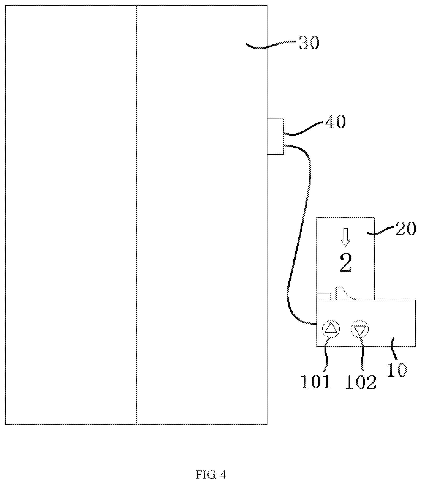
[0009] FIG. 4 is a perspective view of the elevator button pressing module mounted on the elevator floor control panel; and
[0010] FIG. 5 is a perspective view of a mobile robot using the elevator button pressing module.
DETAILED DESCRIPTION OF THE EMBODIMENT(S)
[0011] The technical solution of the disclosure will be described in detail in the following embodiments with reference to the accompanying drawings. In the specification, the same or similar reference numerals denote the same or similar components. The following description of the embodiments of the present disclosure with reference to the accompanying drawings is intended to explain the general inventive concept of the disclosure and should not be construed as a limitation of the present disclosure.
[0012] In addition, in the following detailed description, for purposes of explanation, numerous specific details are set forth in order to provide a thorough understanding of the embodiments of the disclosure. However, one or more embodiments may be practiced without these specific details. In other instances, well-known structures and devices are shown in schematic form in order to simplify the drawing.
[0013] A system for a mobile robot 1 to autonomously take an elevator, as shown in FIGS. 1-5, comprises an elevator button pressing module 10. The elevator button pressing module 10 is mounted on an elevator floor control panel 20 of the elevator. The elevator button pressing module 10 communicates with the mobile robot 1 wirelessly, and is adapted to press corresponding elevator buttons 21, 22 on the elevator floor control panel 20 according to an instruction issued by the mobile robot 1 to call an elevator car.
[0014] The elevator button pressing module 10, as shown in FIGS. 1 and 2, includes a housing 100, a pair of virtual fingers 111, 112, a driver 113, and a controller 114.
[0015] As shown in FIGS. 1-5, the housing 100 is adapted to be mounted on the elevator floor control panel 20, and has a back side 120 facing the elevator floor control panel 20, and a front side 110 facing away from the elevator floor control panel 20.
[0016] The virtual fingers 111, 112, as shown in FIG. 2, are provided on the back side 120 of the housing 100 and are configured to be movable relative to the housing 100. The driver 113 is provided in the housing 100 and is used for driving the virtual fingers 111, 112 to move. The controller 114 is provided in the housing 100 and is used to control the driver 113.
[0017] The controller 114, shown in FIG. 1, is configured to communicate with the mobile robot 1 wirelessly and is adapted to control the driver 113 according to an instruction issued by the mobile robot 1. The driver 113 is adapted to drive the virtual finger 111 or 112 to move to press a corresponding elevator button 21 or 22 on the elevator floor control panel 20 under the control of the controller 114.
[0018] The elevator button pressing module 10 further comprises virtual buttons 101, 102. The virtual buttons 101, 102 are provided on the front side 110 of the housing 100, as shown in FIGS. 1, 4, and 5. The driver 113 is configured to, in response to the virtual button 101 or 102 being pressed, drive the virtual finger 111 or 112 to press the elevator button 21 or 22 corresponding to the pressed virtual button 101 or 102 on the elevator floor control panel 20 under the control of the controller 114.
[0019] The elevator button pressing module 10, as shown in FIG. 1, includes a display 103 provided on the front side 110 of the housing 100 and configured to display a working status of the elevator button pressing module 10 and/or the elevator.
[0020] The elevator button pressing module 10 further comprises a data interface 105, as shown in FIGS. 1 and 2. The elevator button pressing module 10 is adapted to be connected to an external device, for example, to an external computer, a sensor, or the like, through the data interface 105.
[0021] The elevator button pressing module 10, as shown in FIGS. 1 and 2, includes a power switch 104. The power switch 104 is provided on the top of the housing 100 and is used to control a power supply to the elevator button pressing module 10.
[0022] As shown in FIGS. 4 and 5, the system further comprises a sensor 40. The sensor 40 is provided near an elevator floor door 30, connected to the controller 114 of the elevator button pressing module 10, and configured for detecting whether or not the elevator floor door 30 is opened. The controller 114 of the elevator button pressing module 10 notifies the mobile robot 1 that it can enter the elevator car when the sensor 40 detects that the elevator floor door 30 has been opened. In various embodiments, the sensor 40 may be a non-contact distance sensor or an image sensor.
[0023] The elevator buttons 21, 22, shown in FIG. 3, include an elevator up button 21 and an elevator down button 22 provided on the elevator floor control panel 20. The elevator button pressing module 10 is adapted to press the elevator up button 21 and the elevator down button 22 on the elevator floor control panel 20.
[0024] The virtual fingers 111, 112, as shown in FIG. 2, include a first virtual finger 111 and a second virtual finger 112. The first virtual finger 111 is used to press the elevator up button 21, and the second virtual finger 112 is used to press the elevator down button 22. The driver 113 drives the first virtual finger 111 to press the elevator up button 21 under the control of the controller 114 when the mobile robot 1 issues an instruction to press the elevator up button 21. The driver 113 drives the second virtual finger 112 to press the elevator down button 22 under the control of the controller 114 when the mobile robot 1 issues an instruction to press the elevator down button 22.
[0025] The virtual buttons 101, 102, as shown in FIGS. 1, 4, and 5, include a first virtual button 101 and a second virtual button 102. The first virtual button 101 corresponds to the elevator up button 21, and the second virtual button 102 corresponds to the elevator down button 22. The driver 113 drives the first virtual finger 111 to press the elevator up button 21 under the control of the controller 114 when the first virtual button 101 is pressed. The driver 113 drives the second virtual finger 112 to press the elevator down button 22 under the control of the controller 114 when the second virtual button 102 is pressed.
[0026] In the foregoing various exemplary embodiments according to the present disclosure, the mobile robot 1 can autonomously take the elevator using the system. Therefore, the present disclosure expands the application range of the robots and does not require any modification to the elevator itself, which will not have any impact on the safety of the elevator.
[0027] Those skilled in the art will appreciate that the above-described embodiments are illustrative and can be modified, and that the structures described in the various embodiments can be freely combined without conflict in structure or principle. Although the present disclosure has been described with reference to the accompanying drawings, the embodiments disclosed in the drawings are intended to be illustrative explanation of the embodiments of the disclosure, and should not be construed as limiting the disclosure. Although several embodiments of the present general inventive concept have been shown and described, it would be appreciated by those skilled in the art that changes may be made in these embodiments without departing from the principles and spirit of the present general inventive concept, and the scope of the present disclosure is defined by the claims and their equivalents.
* * * * *
D00000
D00001
D00002
D00003
D00004
D00005
XML
uspto.report is an independent third-party trademark research tool that is not affiliated, endorsed, or sponsored by the United States Patent and Trademark Office (USPTO) or any other governmental organization. The information provided by uspto.report is based on publicly available data at the time of writing and is intended for informational purposes only.
While we strive to provide accurate and up-to-date information, we do not guarantee the accuracy, completeness, reliability, or suitability of the information displayed on this site. The use of this site is at your own risk. Any reliance you place on such information is therefore strictly at your own risk.
All official trademark data, including owner information, should be verified by visiting the official USPTO website at www.uspto.gov. This site is not intended to replace professional legal advice and should not be used as a substitute for consulting with a legal professional who is knowledgeable about trademark law.