Adjustment Device, Adjustor And Shock Absorber
ZHAN; Yongyong ; et al.
U.S. patent application number 16/814699 was filed with the patent office on 2020-09-17 for adjustment device, adjustor and shock absorber. The applicant listed for this patent is T-MAX (HANGZHOU) TECHNOLOGY CO., LTD.. Invention is credited to Xinfa DU, Tao HE, Songfeng WANG, Yiming WANG, Hongliang XU, Yongyong ZHAN.
| Application Number | 20200290424 16/814699 |
| Document ID | / |
| Family ID | 1000004748101 |
| Filed Date | 2020-09-17 |


View All Diagrams
| United States Patent Application | 20200290424 |
| Kind Code | A1 |
| ZHAN; Yongyong ; et al. | September 17, 2020 |
ADJUSTMENT DEVICE, ADJUSTOR AND SHOCK ABSORBER
Abstract
An adjustment device includes a body, an adjustment inner gear ring, and an adjustment shaft. The body has a cavity therein, has a first end provided with a first hole and a second hole, and has a peripheral wall provided with a third hole. The first hole, the second hole, and the third hole are connected with the cavity. The adjustment inner gear ring is fitted in the cavity, and has a peripheral wall provided with adjustment holes. The adjustment holes have different cross-sectional areas. A second end of the adjustment shaft has an adjustment gear and passes through the second hole into the cavity. The adjustment gear meshes with the adjustment inner gear ring. The adjustment shaft is rotatable to drive rotation of the adjustment inner gear ring so as to enable the third hole to be connected with the cavity through one of the adjustment holes.
| Inventors: | ZHAN; Yongyong; (Hangzhou, CN) ; WANG; Songfeng; (Hangzhou, CN) ; DU; Xinfa; (Hangzhou, CN) ; WANG; Yiming; (Hangzhou, CN) ; XU; Hongliang; (Hangzhou, CN) ; HE; Tao; (Hangzhou, CN) | ||||||||||
| Applicant: |
|
||||||||||
|---|---|---|---|---|---|---|---|---|---|---|---|
| Family ID: | 1000004748101 | ||||||||||
| Appl. No.: | 16/814699 | ||||||||||
| Filed: | March 10, 2020 |
| Current U.S. Class: | 1/1 |
| Current CPC Class: | F16F 2222/12 20130101; B60G 2202/24 20130101; F16H 1/06 20130101; F16F 2228/066 20130101; B60G 2800/162 20130101; F16K 3/029 20130101; F16F 9/44 20130101; F16K 3/08 20130101; F16F 9/065 20130101; B60G 17/08 20130101; B60G 2500/11 20130101; B60G 13/08 20130101; F16F 9/348 20130101; B60G 2206/41 20130101; B60G 2600/20 20130101; F16F 2230/186 20130101 |
| International Class: | B60G 17/08 20060101 B60G017/08; F16F 9/06 20060101 F16F009/06; F16H 1/06 20060101 F16H001/06; F16F 9/348 20060101 F16F009/348; B60G 13/08 20060101 B60G013/08; F16F 9/44 20060101 F16F009/44; F16K 3/08 20060101 F16K003/08; F16K 3/02 20060101 F16K003/02 |
Foreign Application Data
| Date | Code | Application Number |
|---|---|---|
| Mar 11, 2019 | CN | 201910180966.0 |
| Mar 11, 2019 | CN | 201910180983.4 |
| Mar 11, 2019 | CN | 201910180984.9 |
| Mar 11, 2019 | CN | 201920304957.3 |
| Mar 11, 2019 | CN | 201920306364.0 |
| Mar 11, 2019 | CN | 201920306365.5 |
Claims
1. An adjustment device, comprising: a body having a cavity therein, a first end comprising a first hole and a second hole, and a peripheral wall comprising a third hole, all of the first hole, the second hole, and the third hole being connected with the cavity; an adjustment inner gear ring fitted in the cavity, and having a peripheral wall comprising a plurality of adjustment holes running through the peripheral wall, the plurality of adjustment holes being arranged along a circumferential direction of the adjustment inner gear ring and spaced apart from each other, and the plurality of adjustment holes having cross-sectional areas different from each other; and an adjustment shaft having a first end and a second end, the second end of the adjustment shaft having an adjustment gear and passing through the second hole into the cavity, the adjustment gear meshing with the adjustment inner gear ring, and the adjustment shaft being rotatable to drive rotation of the adjustment inner gear ring by the adjustment gear so as to enable the third hole to be connected with the cavity through one of the plurality of adjustment holes.
2. The adjustment device according to claim 1, wherein the cavity further includes a second end, the second end of the cavity is open, the first hole extends from a first end face of the body towards a second end of the body by a first predetermined length, the second hole extends from the first end face of the body towards the second end of the body by a second predetermined length, and the first end of the adjustment shaft extends out of the second hole.
3. The adjustment device according to claim 2, further comprising a valve assembly, wherein the valve assembly comprises: a valve body provided at the second end of the body to close the second end of the cavity, and comprising a first valve opening and a second valve opening, both of the first valve opening and the second valve opening running through the valve body and being connected with the cavity; a first valve sheet provided at a first end of the valve body and located in the cavity, and configured to open or close the first valve opening; and a second valve sheet provided at a second end of the valve body and located outside the cavity, and configured to open or close the second valve opening.
4. The adjustment device according to claim 3, wherein the valve assembly further comprises a first elastic member located in the cavity and configured to press the first valve sheet onto a first end face of the valve body to close the first valve opening.
5. The adjustment device according to claim 4, wherein the second valve sheet is configured as an annular member and has an inner diameter gradually increased along a direction away from the valve body; the valve assembly further comprises a gasket and a fastener, the gasket is located at a side of the second valve sheet away from the valve body and abuts against an inner peripheral surface of the second valve sheet, and the fastener connects the valve body and the gasket to position the second valve sheet at the second end of the valve body.
6. The adjustment device according to claim 5, wherein the fastener is configured as a T-shaped bolt and a nut, the bolt has a first end located in the cavity, the first elastic member is fitted over the first end of the bolt to position the first elastic member, the bolt has a second end penetrating the first valve sheet, the valve body, the second valve sheet, and the gasket and extending out of the cavity, and the nut is fitted with the second end of the bolt.
7. The adjustment device according to claim 1, wherein the body comprises a solid section and a cylindrical section connected to a second end of the solid section, the first hole and the second hole run through the solid section along an axial direction of the body, and an inner cavity of the cylindrical section is formed as the cavity.
8. The adjustment device according to claim 7, wherein a second end face of the solid section comprises a boss extending into the cavity, the first hole and the second hole run through the boss, an annular groove is defined between an outer peripheral surface of the boss and an inner peripheral surface of the cylindrical section, and the adjustment inner gear ring is fitted in the annular groove; the second hole comprises a first hole segment extending from a first end face of the solid section towards the boss, and a second hole segment running through the boss and connected with the first hole segment, the second hole segment has a larger cross-sectional area than the first hole segment, the second hole segment has an opening portion in a peripheral wall thereof, and the adjustment gear is located in the second hole segment and meshes with the adjustment inner gear ring through the opening portion.
9. The adjustment device according to claim 1, wherein the plurality of adjustment holes are arranged in a half circle of the adjustment inner gear ring; the adjustment device further comprises a limiting member in the body, the adjustment inner gear ring has an end face comprising a limiting guide slot extending along the circumferential direction of the adjustment inner gear ring, and the limiting member is slidably fitted in the limiting guide slot.
10. The adjustment device according to claim 1, further comprising: a knob mounted on the first end of the adjustment shaft to drive the adjustment shaft to rotate, an end face of the knob adjacent to the body comprising a plurality of positioning grooves arranged along a circumferential direction of the knob and spaced apart from each other; and a positioning assembly having a first end arranged in a counter bore in a first end face of the body, and a second end selectively fitted in one of the plurality of positioning grooves.
11. The adjustment device according to claim 10, wherein the positioning assembly comprises a second elastic member and a positioning ball, the second elastic member is in the counter bore, and the positioning ball is provided at an end of the second elastic member and selectively fitted in one of the plurality of positioning grooves.
12. The adjustment device according to claim 1, wherein the cross-sectional areas of the plurality of adjustment holes are gradually decreased along the circumferential direction of the adjustment inner gear ring.
13. The adjustment device according to claim 1, wherein the body comprises a recess in an outer peripheral surface thereof, and the third hole is connected with the recess.
14. The adjustment device according to claim 2, wherein the cross-sectional areas of the plurality of adjustment holes are gradually decreased along the circumferential direction of the adjustment inner gear ring.
15. The adjustment device according to claim 2, wherein the body comprises a recess in an outer peripheral surface thereof, and the third hole is connected with the recess.
16. An adjustor, comprising: a first cylinder body having a first inner cavity; a first piston movably provided in the first inner cavity; and an adjustment device coupled to a first end of the first cylinder body, wherein the adjustment device, comprising: a body having a cavity therein, a first end comprising a first hole and a second hole, and a peripheral wall comprising a third hole, all of the first hole, the second hole, and the third hole being connected with the cavity, an adjustment inner gear ring fitted in the cavity, and having a peripheral wall comprising a plurality of adjustment holes running through the peripheral wall, the plurality of adjustment holes being arranged along a circumferential direction of the adjustment inner gear ring and spaced apart from each other, and the plurality of adjustment holes having cross-sectional areas different from each other, and an adjustment shaft having a first end and a second end, the second end of the adjustment shaft having an adjustment gear and passing through the second hole into the cavity, the adjustment gear meshing with the adjustment inner gear ring, and the adjustment shaft being rotatable to drive rotation of the adjustment inner gear ring by the adjustment gear so as to enable the third hole to be connected with the cavity through one of the plurality of adjustment holes.
17. A shock absorber, comprising: a first cylinder body having a first inner cavity; a first piston movably provided in the first inner cavity; a second cylinder body having a second inner cavity; a second piston movably provided in the second inner cavity; an adjustment device; and a connecting pipe connected with the second inner cavity, and connected with the first inner cavity by means of the adjustment device, wherein the adjustment device, comprising: a body having a cavity therein, a first end comprising a first hole and a second hole, and a peripheral wall comprising a third hole, all of the first hole, the second hole, and the third hole being connected with the cavity, an adjustment inner gear ring fitted in the cavity, and having a peripheral wall comprising a plurality of adjustment holes running through the peripheral wall, the plurality of adjustment holes being arranged along a circumferential direction of the adjustment inner gear ring and spaced apart from each other, and the plurality of adjustment holes having cross-sectional areas different from each other, and an adjustment shaft having a first end and a second end, the second end of the adjustment shaft having an adjustment gear and passing through the second hole into the cavity, the adjustment gear meshing with the adjustment inner gear ring, and the adjustment shaft being rotatable to drive rotation of the adjustment inner gear ring by the adjustment gear so as to enable the third hole to be connected with the cavity through one of the plurality of adjustment holes.
18. The shock absorber according to claim 17, wherein an outer peripheral surface of the body is fitted with an inner peripheral surface of the first cylinder body and comprises a recess, and the third hole is connected with the first inner cavity through the recess.
19. The shock absorber according to claim 17, wherein the first piston divides the first inner cavity into an inner cavity adjacent to a first end of the first cylinder body and an inner cavity adjacent to a second end of the first cylinder body, wherein the inner cavity adjacent to the second end of the first cylinder body contains gas, while the inner cavity adjacent to the first end of the first cylinder body contains oil.
20. The shock absorber according to claim 19, wherein when the oil flows into the first inner cavity from the second inner cavity, the oil in the second inner cavity flows into the inner cavity adjacent to the first end of the first cylinder body through the connecting pipe and the adjustment device sequentially, to push the first piston to move in a direction from the first end of the first cylinder body toward the second end of the first cylinder body, so as to compress the gas; when the oil flows into the second inner cavity from the first inner cavity, the gas in the inner cavity adjacent to the second end of the first cylinder body is released to push the first piston to move in a direction from the second end of the first cylinder body to the first end of the first cylinder body, such that the oil flows into the second inner cavity through the adjustment device and the connecting pipe sequentially.
Description
CROSS-REFERENCE TO RELATED APPLICATIONS
[0001] This application claims priority to and benefits of Chinese Patent Application Serial No. 201910180984.9, filed with National Intellectual Property Administration of the People's Republic of China (PRC) on Mar. 11, 2019, Chinese Patent Application Serial No. 201920304957.3, filed with National Intellectual Property Administration of PRC on Mar. 11, 2019, Chinese Patent Application Serial No. 201910180966.0, filed with National Intellectual Property Administration of PRC on Mar. 11, 2019, Chinese Patent Application Serial No. 201920306364.0, filed with National Intellectual Property Administration of PRC on Mar. 11, 2019, Chinese Patent Application Serial No. 201910180983.4, filed with National Intellectual Property Administration of PRC on Mar. 11, 2019, and Chinese Patent Application Serial No. 201920306365.5, filed with National Intellectual Property Administration of PRC on Mar. 11, 2019, the entire contents of which are incorporated herein by reference.
TECHNICAL FIELD
[0002] The present disclosure relates to a field of shock absorption technology.
BACKGROUND
[0003] A vehicle shock absorber is used to reduce vibration of a vehicle frame and a vehicle body, and improve travelling stability and comfort of the vehicle. If the shock absorber is too soft, the vehicle body is prone to bounce up and down; if the shock absorber is too hard, large resistance may be caused and hinder a spring from working properly. Thus, in order to meet the needs of different vehicles, it is necessary to install shock absorbers with different hardnesses.
[0004] In the related art, in order to adapt to different needs, an adjustment device is provided to adjust the hardness of the shock absorber. However, the adjustment device in the related art has a narrow adjustment range and a poor adjustment effect, and hence the hardness of the shock absorber is unsatisfactorily adjusted.
SUMMARY
[0005] The present disclosure aims to solve one of the technical problems in the related art at least to some extent.
[0006] To this end, embodiments of an aspect of the present disclosure provide an adjustment device that can adjust the hardness of a shock absorber and has a wide adjustment range and an excellent adjustment effect.
[0007] Embodiments of another aspect of the present disclosure provide an adjustor.
[0008] Embodiments of still another aspect of the present disclosure provide a shock absorber.
[0009] The adjustment device according to embodiments of the first aspect of the present disclosure includes: a body having a cavity therein, and having a first end provided with a first hole and a second hole and a peripheral wall provided with a third hole, all of the first hole, the second hole, and the third hole being communicated with the cavity; an adjustment inner gear ring fitted in the cavity, and having a peripheral wall provided with a plurality of adjustment holes running through the peripheral wall, the plurality of adjustment holes being arranged along a circumferential direction of the adjustment inner gear ring and spaced apart from each other, and the plurality of adjustment holes having cross-sectional areas different from each other; and an adjustment shaft having a first end and a second end, the second end of the adjustment shaft having an adjustment gear and passing through the second hole into the cavity, the adjustment gear meshing with the adjustment inner gear ring, and the adjustment shaft being rotatable to drive rotation of the adjustment inner gear ring by the adjustment gear so as to enable the third hole to be communicated with the cavity through one of the plurality of adjustment holes.
[0010] In the adjustment device according to embodiments of the present disclosure, by configuring the cross-sectional areas of the plurality of adjustment holes of the adjustment inner gear ring to be different from each other, and by driving the adjustment inner gear ring to rotate by means of the adjustment gear to enable the third hole to be communicated with the cavity through one of the plurality of adjustment holes, the first hole is communicated with the third hole through the cavity and one of the plurality of adjustment holes. The flow rate of the oil which is allowed to pass through different adjustment holes is different, such that the adjustment for the hardness of the shock absorber can be realized. Moreover, since the adjustment inner gear ring has a relatively large diameter, more adjustment holes can be provided in the adjustment inner gear ring, and the cross-sectional areas of the adjustment holes can vary in a wider range, thereby resulting in a wider adjustment range and improving the adjustment effect.
[0011] The adjustor according to embodiments of another aspect of the present disclosure includes: a first cylinder body having a first inner cavity; a first piston movably provided in the first inner cavity; and an adjustment device provided at a first end of the first cylinder body and configured as the adjustment device described in the above embodiments.
[0012] The shock absorber according to embodiments of still another aspect of the present disclosure includes: a first cylinder body having a first inner cavity; a first piston movably provided in the first inner cavity; a second cylinder body having a second inner cavity; a second piston movably provided in the second inner cavity; an adjustment device configured as the adjustment device described in the above embodiments; and a connecting pipe communicated with the second inner cavity, and communicated with the first inner cavity by means of the adjustment device.
BRIEF DESCRIPTION OF THE DRAWINGS
[0013] FIG. 1 is an exploded view of an adjustment device according to embodiments of the present disclosure.
[0014] FIG. 2 is a sectional view of an adjustment device according to embodiments of the present disclosure, in which a position of a first hole is illustrated.
[0015] FIG. 3 is a sectional view of a body of an adjustment device according to embodiments of the present disclosure.
[0016] FIG. 4 is a sectional view of an adjustment device according to embodiments of the present disclosure, in which a position of a positioning assembly is illustrated.
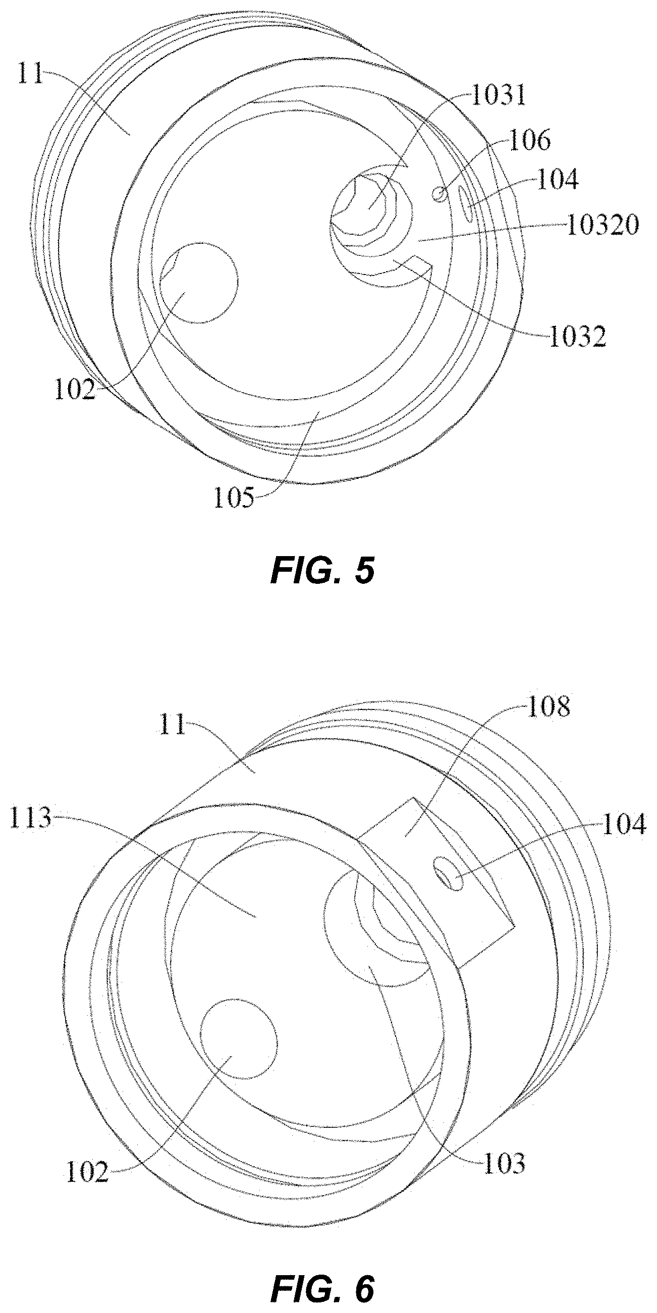
[0017] FIG. 5 is a schematic view of a body of an adjustment device according to embodiments of the present disclosure, in which a position of an opening portion is illustrated.
[0018] FIG. 6 is a schematic view of a body of an adjustment device according to embodiments of the present disclosure, in which a position of a recess is illustrated.
[0019] FIG. 7 is a schematic view of an adjustment inner gear ring of an adjustment device according to embodiments of the present disclosure.
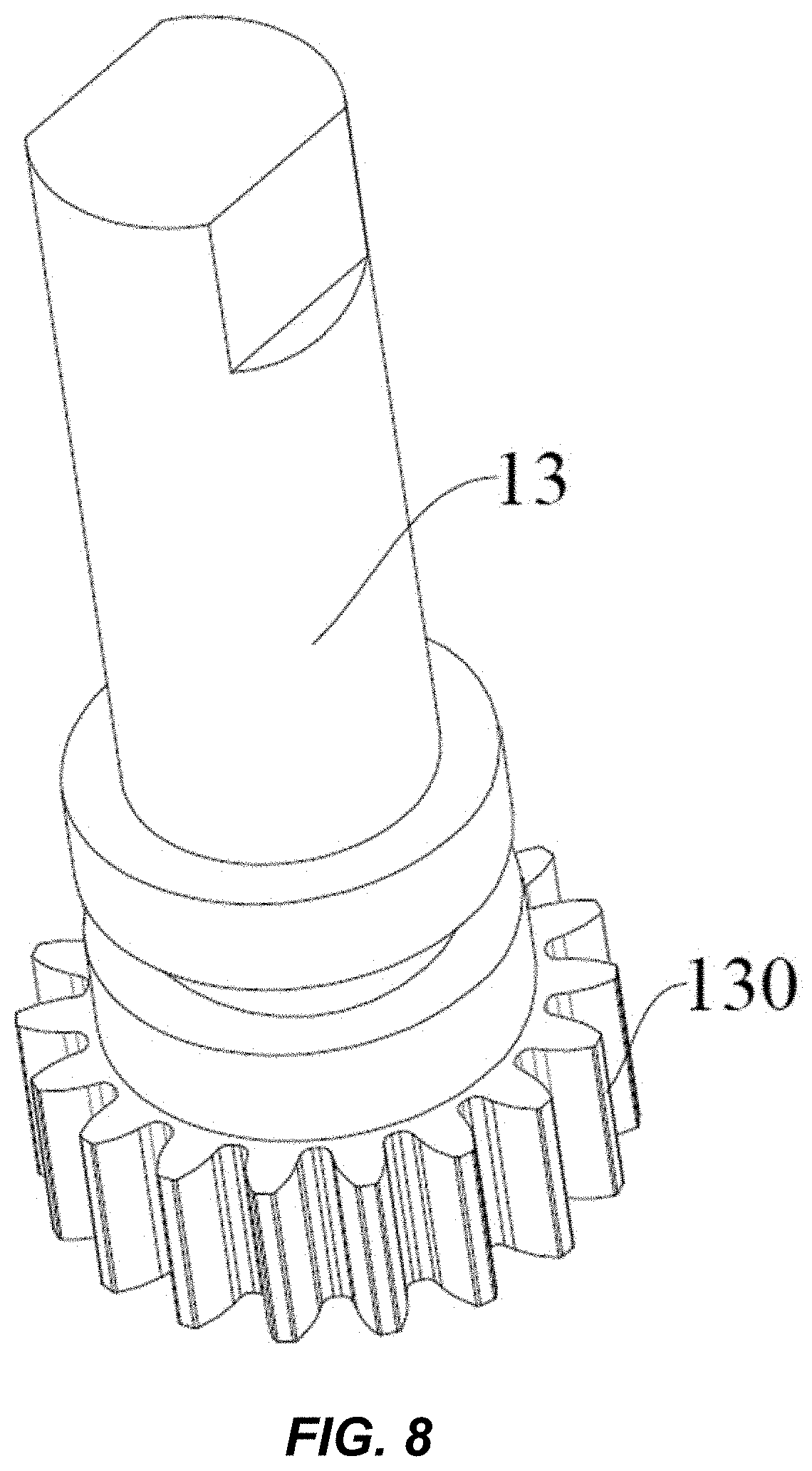
[0020] FIG. 8 is a schematic view of an adjustment shaft of an adjustment device according to embodiments of the present disclosure.
[0021] FIG. 9 is a schematic view of a valve body of an adjustment device according to embodiments of the present disclosure, in which a first end of the valve body is illustrated.
[0022] FIG. 10 is a schematic view of a valve body of an adjustment device according to embodiments of the present disclosure, in which a second end of the valve body is illustrated.
[0023] FIG. 11 is a schematic view of a second valve sheet of an adjustment device according to embodiments of the present disclosure.
[0024] FIG. 12 is a schematic view of a knob of an adjustment device according to embodiments of the present disclosure.
[0025] FIG. 13 is a schematic view of a shock absorber according to embodiments of the present disclosure, in which oil flows from a second inner cavity into a first inner cavity.
[0026] FIG. 14 is a partially enlarged view of FIG. 13.
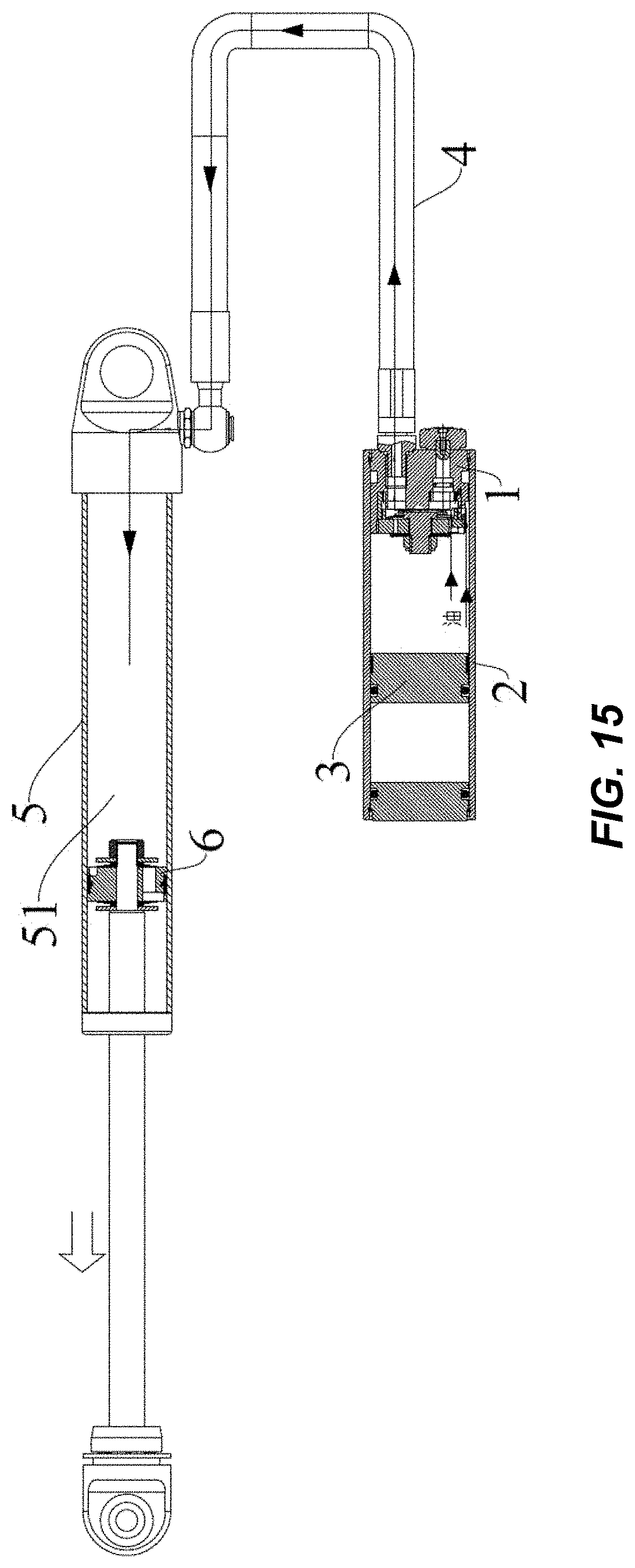
[0027] FIG. 15 is a schematic view of a shock absorber according to embodiments of the present disclosure, in which oil flows from a first inner cavity into a second inner cavity.
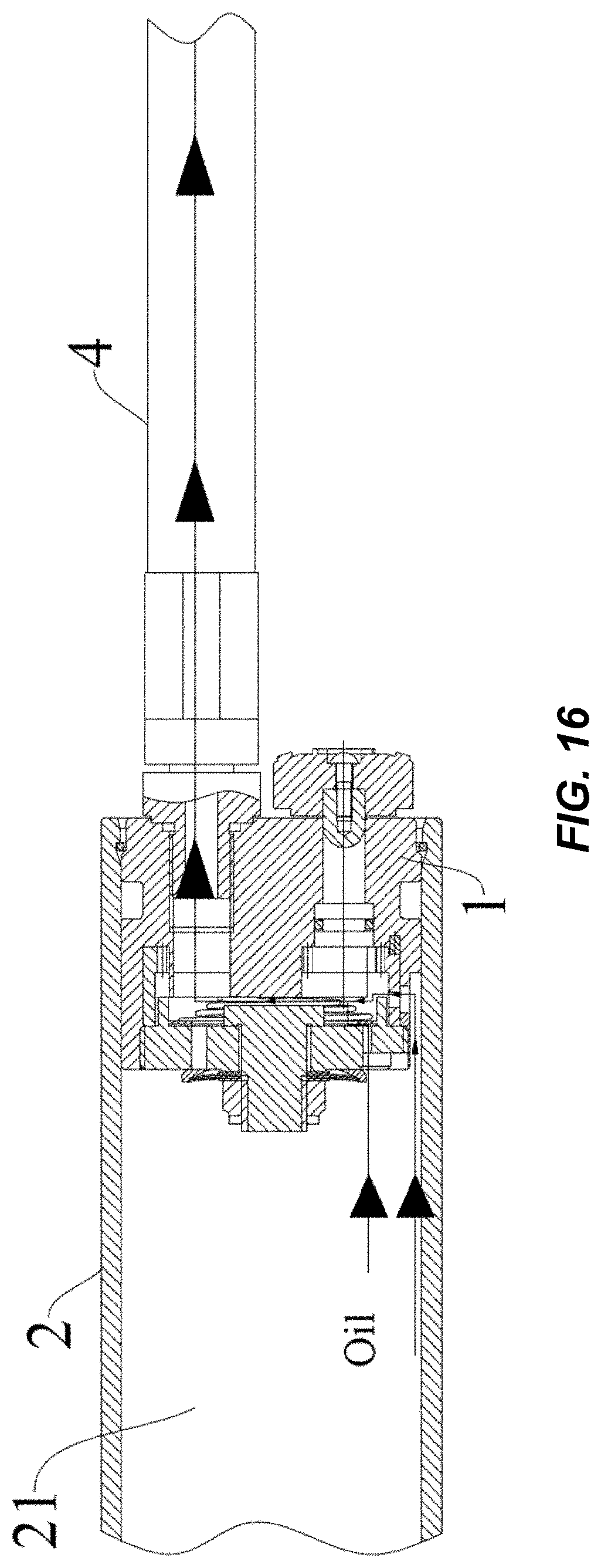
[0028] FIG. 16 is a partially enlarged view of FIG. 15.
[0029] Reference numerals include the following:
adjustment device 1, body 11, first end (solid section) 111 of body, second end (cylindrical section) 112 of body, boss 113, cavity 101, first end 1011 of cavity, second end 1012 of cavity, first hole 102, second hole 103, first hole segment 1031, second hole segment 1032, opening portion 10320, third hole 104, annular groove 105, counter bore 107, recess 108, adjustment inner gear ring 12, adjustment hole 120, limiting guide slot 121, adjustment shaft 13, first end 131 of adjustment shaft, second end 132 of adjustment shaft, adjustment gear 133, valve assembly 14, valve body 141, first end 1411 of valve body, second end 1412 of valve body, first valve opening 1413, second valve opening 1414, first valve sheet 142, second valve sheet 143, first elastic member 144, gasket 145, fastener 146, T-shaped bolt 1461, nut 1462, limiting member 15, knob 16, positioning assembly 17, second elastic member 171, positioning ball 172, first cylinder body 2, first inner cavity 21, first piston 3, connecting pipe 4, second cylinder body 5, second inner cavity 51, second piston 6.
DETAILED DESCRIPTION
[0030] Embodiments of the present disclosure will be described in detail and examples of the embodiments will be illustrated in the drawings. The embodiments described below with reference to the drawings are illustrative and used to generally understand the present disclosure. The embodiments shall not be construed to limit the present disclosure. In the specification, it is to be understood that terms such as "central," "longitudinal," "transverse," "length," "width," "thickness," "upper," "lower," "front," "rear," "left," "right," "vertical," "horizontal," "top," "bottom," "inner," "outer," "clockwise," "counterclockwise," "axial," "radial," and "circumferential" should be construed to refer to the orientation or position relationship as then described or as shown in the drawings under discussion. These relative terms are for convenience of description and do not indicate or imply that any feature of the present disclosure should have a particular orientation, or be constructed and operated in a particular orientation. Thus, these terms shall not be construed to limit the present disclosure.
[0031] A shock absorber according to embodiments of the present disclosure will be described with reference to the drawings.
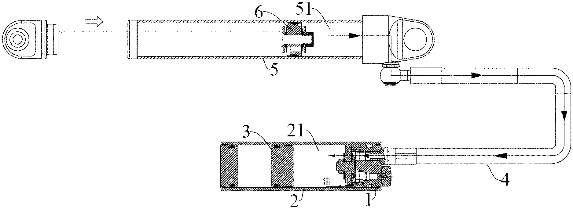
[0032] As illustrated in FIGS. 13-16, the shock absorber according to embodiments of the present disclosure includes a first cylinder body 2, a first piston 3, a connecting pipe 4, a second cylinder body 5, a second piston 6, and an adjustment device 1. The first cylinder body 2 has a first inner cavity 21, and the first piston 3 is movably provided in the first inner cavity 21. The second cylinder body 5 has a second inner cavity 51, and the second piston 6 is movably provided in the second inner cavity 51. The connecting pipe 4 is in communication with the second inner cavity 51, and is communicated with the first inner cavity 21 through the adjustment device 1. In the description of the present disclosure, terms such as "first" and "second" are used herein for purposes of description and are not intended to indicate or imply relative importance or significance.
[0033] As illustrated in FIGS. 14 and 15, the adjustment device 1 is provided in a right end of the first inner cavity 21, and the connecting pipe 4 has a lower end communicated with the first inner cavity 21 through the adjustment device 1 and an upper end communicated with the second inner cavity 51.
[0034] The adjustment device according to embodiments of the present disclosure will be described with reference to the drawings.
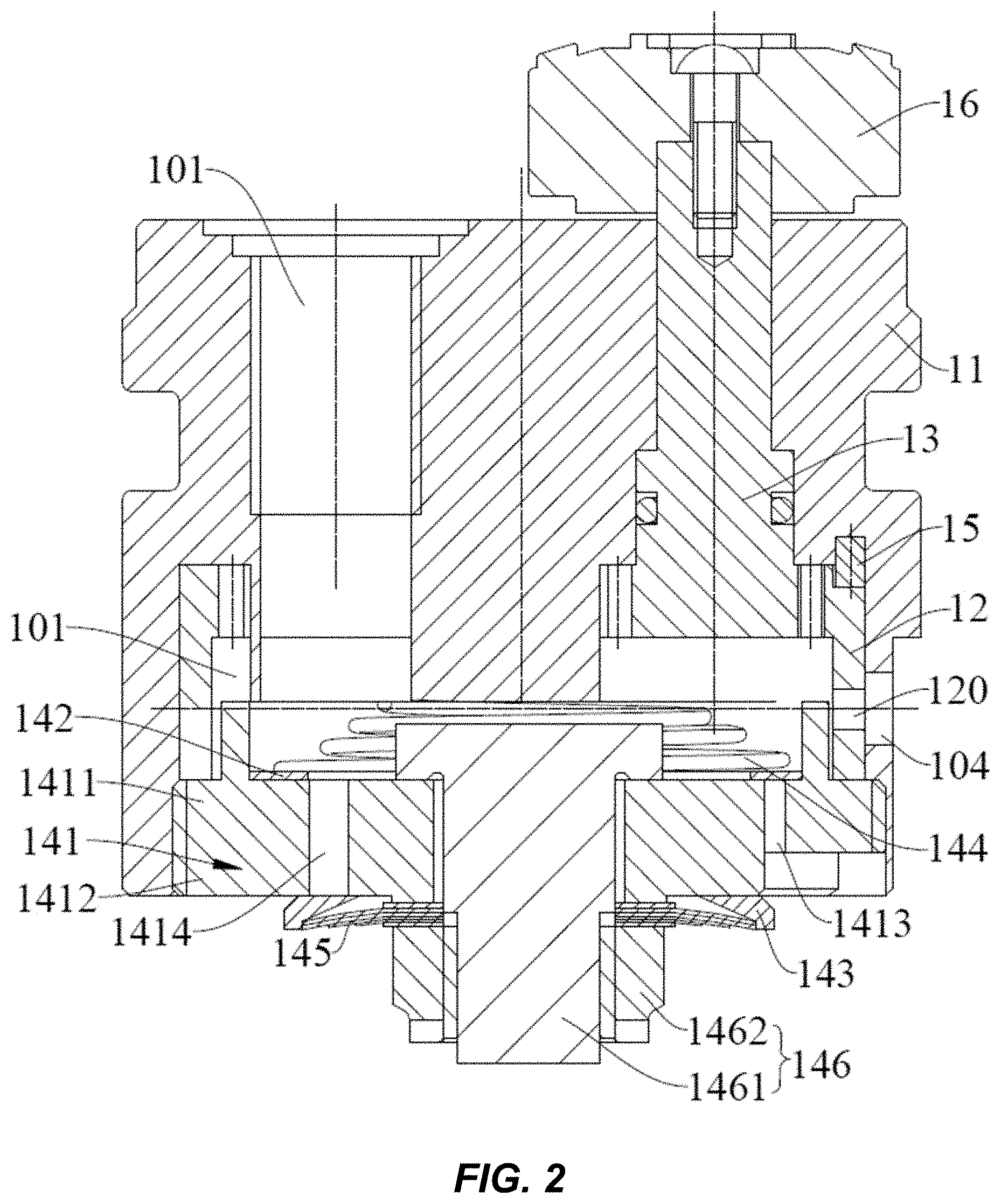
[0035] As illustrated in FIGS. 1-3, the adjustment device 1 according to embodiments of the present disclosure includes a body 11, an adjustment inner gear ring 12, and an adjustment shaft 13.
[0036] The body 11 has a cavity 101 therein, a first end 111 of the body 11 (an upper end of the body 11 as shown in FIG. 2) is provided with a first hole 102 and a second hole 103, and the first hole 102 is in communication with an inner cavity of the connecting pipe 4. A third hole 104 is provided in a peripheral wall of the body 11 and is communicated with the first inner cavity 21. The first hole 102, the second hole 103, and the third hole 104 are all communicated with the cavity 101. As illustrated in FIGS. 2 and 3, the cavity 101 is defined in a lower end of the body 11, the first hole 102 and the second hole 103 are provided in the upper end of the body 11, and both of a lower end of the first hole 102 and a lower end of the second hole 103 are communicated with the cavity 101. The third hole 104 is provided in a lower end of the peripheral wall of the body 11 and runs through the peripheral wall to make the third hole 104 communicated with the cavity 101.
[0037] As illustrated in FIGS. 2 and 7, the adjustment inner gear ring 12 is fitted in the cavity 101 and has a peripheral wall provided with a plurality of adjustment holes 120 running through this peripheral wall. The plurality of adjustment holes 120 are arranged along a circumferential direction of the adjustment inner gear ring 12 and spaced apart from each other, and the plurality of adjustment holes 120 have cross-sectional areas different from each other. In the description of the present disclosure, unless specified otherwise, the term "a plurality of" means at least two, such as two, three, etc.
[0038] As illustrated in FIGS. 2, 3 and 8, the adjustment shaft 13 has a first end 131 and a second end 132. The second end 132 of the adjustment shaft 13 has an adjustment gear 133 and passes through the second hole 103 into the cavity 101. The adjustment gear 133 meshes with the adjustment inner gear ring 12. The adjustment shaft 13 is rotatable to drive rotation of the adjustment inner gear ring 12 by the adjustment gear 133, such that the third hole 104 is communicated with the cavity 101 through one of the plurality of adjustment holes 120.
[0039] In the adjustment device 1 according to embodiments of the present disclosure, the adjustment shaft 13 is rotatable about its axis to drive the adjustment inner gear ring 12 to rotate about an axis of the adjustment inner gear ring 12 by means of the adjustment gear 133. Through the rotation of the adjustment inner gear ring 12, any one of the plurality of adjustment holes 120 in the adjustment inner gear ring 12 can communicate the third hole 104 with the cavity 101, such that oil flowing into the cavity 101 through the connecting pipe 4 and the first hole 102 flows into the first inner cavity 21 through one of the plurality of adjustment holes 120 via the third hole 104, or oil in the first inner cavity 21 flows into the cavity 101 through the third hole 104 and one of the plurality of adjustment holes 120 and flows into the second inner cavity 51 through the first hole 102 and the connecting pipe 4. Moreover, since the cross-sectional areas of the plurality of adjustment holes 120 are different from each other, the flow rate of the oil entering the third hole 104 through different adjustment holes 120 is different.
[0040] In the adjustment device 1 according to embodiments of the present disclosure, by configuring the cross-sectional areas of the plurality of adjustment holes 120 of the adjustment inner gear ring 12 to be different from each other, and by configuring the adjustment shaft 13 to be rotatable to drive the rotation of the adjustment inner gear ring 12 by the adjustment gear 133 to enable the third hole 104 to be communicated with the cavity 101 through one of the plurality of adjustment holes 120, the first hole 102 is communicated with the third hole 104 through the cavity 101 and one of the plurality of adjustment holes 120. The flow rate of the oil which is allowed to pass through different adjustment holes 120 is different, and a compression force and a restoring force of the shock absorber can be adjusted by the different flow rates of the oil, thereby realizing the adjustment for the hardness of the shock absorber. Moreover, since the adjustment inner gear ring 12 has a relatively large diameter, more adjustment holes 120 can be provided in the adjustment inner gear ring 12, and the cross-sectional areas of the plurality of adjustment holes 120 can vary in a wider range, thereby resulting in a wider adjustment range and improving the adjustment effect.
[0041] In some specific embodiments, the cross-sectional areas of the plurality of adjustment holes 120 are gradually decreased along the circumferential direction of the adjustment inner gear ring 12. As illustrated in FIG. 7, the cross sections of the adjustment holes 120 are circular, and diameters of the plurality of adjustment holes 120 are gradually decreased along the circumferential direction of the adjustment inner gear ring 12.
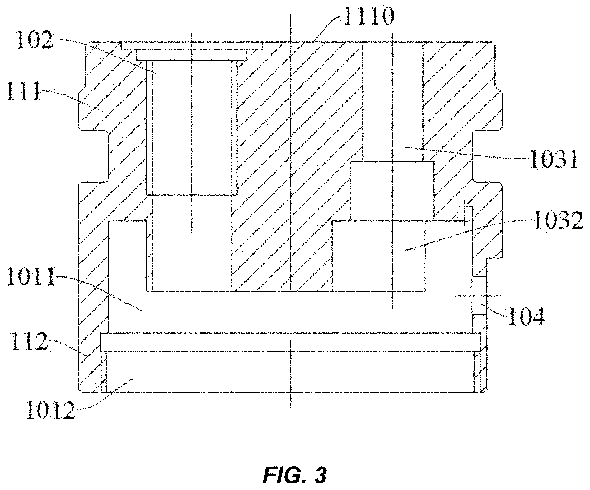
[0042] In some embodiments, the cavity 101 has a first end 1011 (an upper end of the cavity 101 as shown in FIG. 3) and a second end 1012 (a lower end of the cavity 101 as shown in FIG. 3), and the second end 1012 of the cavity 101 is open.
[0043] The first hole 102 extends from a first end face 1110 of the body 11 (an upper end face of the body 11 as shown in FIG. 3) towards a second end 112 of the body 11 (a lower end of the body 11 as shown in FIG. 3) by a first predetermined length. As illustrated in FIG. 3, the first hole 102 extends downwardly from the upper end face of the body 11 by the first predetermined length. The second hole 103 extends from the first end face 1110 of the body 11 towards the second end 112 of the body 11 by a second predetermined length. As illustrated in FIG. 3, the second hole 103 extends downwardly from the upper end face of the body 11 by the second predetermined length.
[0044] The first end 131 of the adjustment shaft 13 (an upper end of the adjustment shaft 13 as shown in FIGS. 2-4) extends out of the second hole 103. As illustrated in FIGS. 2-3, the upper end of the adjustment shaft 13 extends out of the second hole 103, that is, an upper end face of the adjustment shaft 13 is located above the second hole 103.
[0045] In some embodiments, as illustrated in FIG. 2 and FIGS. 9-11, the adjustment device 1 further includes a valve assembly 14, and the valve assembly 14 includes a valve body 141, a first valve sheet 142, and a second valve sheet 143.
[0046] The valve body 141 is provided at the second end 112 of the body 11 to close the second end 1012 of the cavity 101. The valve body 141 is provided with a first valve opening 1413 and a second valve opening 1414, both of which run through the valve body 141 and are communicated with the cavity 101.
[0047] As illustrated in FIGS. 9 and 10, three first valve openings 1413 and three second valve openings 1414 are provided. The three first valve openings 1413 are arranged along a circumferential direction of the valve body 141 and spaced apart from each other. The three second valve openings 1414 are arranged along the circumferential direction of the valve body 141 and spaced apart from each other. The first valve openings 1413 and the second valve openings 1414 are alternately arranged one by one. Each of the first valve openings 1413 has an arc cross section, and each of the second valve openings 1414 has a circular cross section. A lower end face of the valve body 141 is further provided with three arc-shaped grooves 1415 spaced apart along the circumferential direction of the valve body 141, and the first valve opening 1413 has a lower end communicated with the arc-shaped groove 1415.
[0048] The first valve sheet 142 is provided at a first end 1411 of the valve body 141 (an upper end of the valve body 141 as shown in FIG. 2) and located in the cavity 101, and the first valve sheet 142 is configured to open or close the first valve opening 1413. As illustrated in FIG. 2, the first valve sheet 142 is arranged at the upper end of the valve body 141 and located in the cavity 101, and the first valve sheet 142 can open or close an upper end face of the first valve opening 1413. When the first valve sheet 142 opens the upper end face of the first valve opening 1413, the cavity 101 is communicated with the outside through the first valve opening 1413. When the first valve sheet 142 closes the upper end face of the first valve opening 1413, the cavity 101 is not in communication with the outside.
[0049] The second valve sheet 143 is provided at a second end 1412 of the valve body 141 (a lower end of the valve body 141 as shown in FIG. 2) and located outside the cavity 101, and the second valve sheet 143 is configured to open or close the second valve opening 1414. As illustrated in FIG. 2, the second valve sheet 143 is provided at the lower end of the valve body 141 and located outside the cavity 101, and the second valve sheet 143 can open or close a lower end face of the second valve opening 1414. When the second valve sheet 143 opens the lower end face of the second valve opening 1414, the cavity 101 is communicated with the outside through the second valve opening 1414. When the second valve sheet 143 closes the lower end face of the second valve opening 1414, the cavity 101 is not in communication with the outside.
[0050] In some specific embodiments, as illustrated in FIG. 2, the first valve sheet 142 is configured as an annular member, has a lower end face capable of closing the first valve opening 1413, and has an inner cavity opposite the second valve opening 1414. The second valve sheet 143 is configured as an annular member, has an upper end face capable of closing the second valve opening 1414, and is offset from the first valve opening 1413 in a radial direction of the body 11.
[0051] In some embodiments, the valve assembly 14 further includes a first elastic member 144, and the first elastic member 144 is located in the cavity 101 and configured to press the first valve sheet 142 onto a first end face 14110 of the valve body 141 to close the first valve opening 1413. As illustrated in FIG. 2, the first elastic member 144 is arranged in the cavity 101, the first elastic member 144 has an upper end in contact with a lower end face of a boss 113 and a lower end in contact with an upper end face of the first valve sheet 142, and the first elastic member 144 is in a compressed state, such that the first valve sheet 142 is pressed onto an upper end face of the valve body 141 by means of the first elastic member 144, thereby enabling the first valve sheet 142 to close the first valve opening 1413.
[0052] In some embodiments, the second valve sheet 143 is configured as an annular member and has an inner diameter gradually increased along a direction away from the valve body 141 (i.e., an up-to-down direction shown in FIG. 2 and a down-to-up direction shown in FIG. 11). As illustrated in FIG. 2, the inner diameter of the second valve sheet 143 is gradually increased from up to down, and the upper end face of the second valve sheet 143 can close the second valve opening 1414.
[0053] The valve assembly 14 further includes a gasket 145 and a fastener 146, and the gasket 145 is located at a side of the second valve sheet 143 away from the valve body 141 (a lower end of the second valve sheet 143 as shown in FIG. 2) and abuts against an inner peripheral surface of the second valve sheet 143. As illustrated in FIG. 2, the gasket 145 is located at the lower end of the second valve sheet 143, and an outer peripheral surface of the gasket 145 abuts against the inner peripheral surface of the second valve sheet 143.
[0054] The fastener 146 connects the valve body 141 and the gasket 145 to position the second valve sheet 143 at the second end 1412 of the valve body 141. As illustrated in FIG. 2, the fastener 146 connects the valve body 141 and the gasket 145, and positions the second valve sheet 143 at the lower end of the valve body 141 by the gasket 145 abutting against the inner peripheral surface of the second valve sheet 143. It could be understood that one or a plurality of gaskets 145 can be provided, and the number of the gaskets 145 can be determined in the light of specific conditions.
[0055] In some embodiments, the fastener 146 is configured as a T-shaped bolt 1461 and a nut 1462. The bolt 1461 has a first end located in the cavity 101, and the first elastic member 144 is fitted over the first end of the bolt 1461 (an upper end of the bolt 1461 as shown in FIG. 2), such that the first elastic member 144 is positioned. The bolt 1461 has a second end (a lower end of the bolt 1461 as shown in FIG. 2) penetrating the first valve sheet 142, the valve body 141, the second valve sheet 143 and the gasket 145 and extending out of the cavity 101, and the nut 1462 is fitted with the second end of the bolt 1461, such that the valve body 141 and the gasket 145 are connected by the fitting between the bolt 1461 and the nut 1462.
[0056] In some embodiments, the body 11 includes a solid section 111 and a cylindrical section 112 connected to a second end of the solid section 111 (a lower end of the solid section 111 as shown in FIG. 3). The first hole 102 and the second hole 103 run through the solid section 111 along an axial direction of the body 11 (an up-and-down direction as shown in FIG. 3), and an inner cavity of the cylindrical section 112 is formed as the cavity 101. As illustrated in FIG. 3, the body 11 includes the solid section 111 and the cylindrical section 112 connected with each other, in which the solid section 111 exhibits a cylindrical shape and has an axial direction consistent with an axial direction of the cylindrical section 112.
[0057] In some embodiments, a second end face of the solid section 111 (a lower end face of the solid section 111 as shown in FIG. 2) is provided with the boss 113 extending into the cavity 101, the first hole 102 and the second hole 103 run through the boss 113, and an annular groove 105 is defined between an outer peripheral surface of the boss 113 and an inner peripheral surface of the cylindrical section 112. As illustrated in FIG. 3, the lower end face of the solid section 111 is provided with the boss 113 extending downwards and extending into the cavity 101, the first hole 102 and the second hole 103 run through the solid section 111 and the boss 113, and the annular groove 105 is defined between the outer peripheral surface of the boss 113 and the inner peripheral surface of the cylindrical section 112.
[0058] As illustrated in FIGS. 2 and 3, the adjustment inner gear ring 12 is fitted in the annular groove 105.
[0059] The second hole 103 includes a first hole segment 1031 and a second hole segment 1032. The first hole segment 1031 extends from a first end face of the solid section 111 (an upper end face of the solid section 111 as shown in FIG. 3) towards the boss 113. The second hole segment 1032 runs through the boss 113 and is communicated with the first hole segment 1031. The second hole segment 1032 has a larger cross-sectional area than the first hole segment 1031. A peripheral wall of the second hole segment 1032 has an opening portion 10320. The adjustment gear 133 is located in the second hole segment 1032 and meshes with the adjustment inner gear ring 12 through the opening portion 10320.
[0060] In some embodiments, the plurality of adjustment holes 120 are arranged in a half circle of the adjustment inner gear ring 12. In other words, the half circle of the adjustment inner gear ring 12 is provided with the adjustment holes 120.
[0061] The adjustment device 1 further includes a limiting member 15 provided in the body 11. The adjustment inner gear ring 12 has an end face provided with a limiting guide slot 121 extending along the circumferential direction of the adjustment inner gear ring 12. The limiting member 15 is slidably fitted in the limiting guide slot 121. As illustrated in FIGS. 2, 5 and 7, the lower end face of the solid section 111 is provided with an orifice 106 extending downwards, an upper end face of the adjustment inner gear ring 12 is provided with the limiting guide slot 121, and the limiting guide slot 121 extends along the circumferential direction of the adjustment inner gear ring 12 and extends by the half circle of the adjustment inner gear ring 12. The limiting member 15 has an upper end provided in the orifice 106 and a lower end slidably fitted in the limiting guide slot 121. For the adjustment device 1 according to embodiments of the present disclosure, the rotation of the adjustment inner gear ring 12 can be limited to a range having the adjustment holes 120 by means of the limiting member 15 and the limiting guide slot 121, thereby improving the adjustment efficiency.
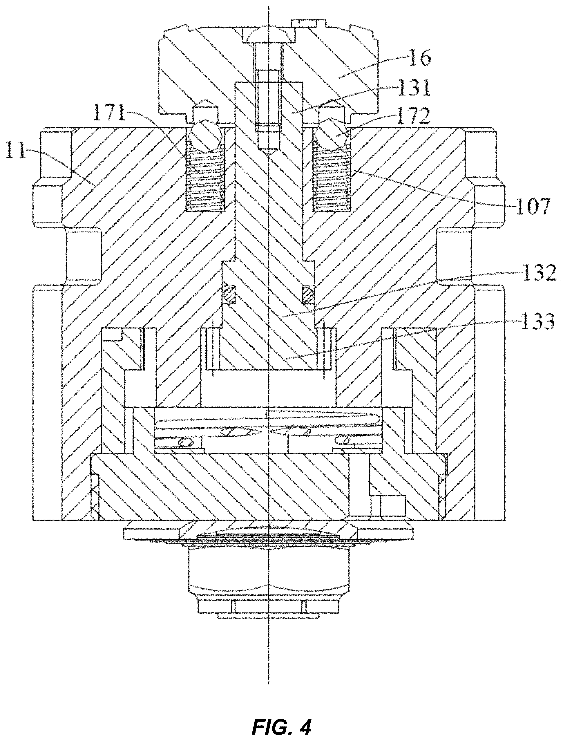
[0062] In some embodiments, as illustrated in FIGS. 3 and 12, the adjustment device 1 further includes a knob 16 and a positioning assembly 17. The knob 16 is mounted on the first end 131 of the adjustment shaft 13 to drive the adjustment shaft 13 to rotate, and an end face of the knob 16 adjacent to the body 11 (a lower end face of the knob 16 as shown in FIG. 3) is provided with a plurality of positioning grooves 161 arranged along a circumferential direction of the knob 16 and spaced apart from each other.
[0063] The first end face 1110 of the body 11 is provided with a counter bore 107, and the positioning assembly 17 has a first end (an upper end of the positioning assembly 17 as shown in FIG. 3) arranged in the counter bore 107 and a second end (a lower end of the positioning assembly 17 as shown in FIG. 3) selectively fitted in one of the plurality of positioning grooves 161.
[0064] For the adjustment device 1 according to embodiments of the present disclosure, the adjustment shaft 13 can be driven to rotate by rotating the knob 16, such that the adjustment inner gear ring 12 is driven to rotate by means of the adjustment gear 133. By providing the plurality of positioning grooves 161 in the lower end face of the knob 16 and providing the positioning assembly 17 on the adjustment device 1, the knob 16 can be maintained in position when the knob 16 has been rotated by a certain degree to communicate one of the adjustment holes 120 with the third hole 104.
[0065] In some specific embodiments, the positioning assembly 17 includes a second elastic member 171 and a positioning ball 172. The second elastic member 171 is provided in the counter bore 107. The positioning ball 172 is provided at an end of the second elastic member 171 (an upper end of the second elastic member 171 as shown in FIG. 3), and the positioning ball 172 is selectively fitted in one of the plurality of positioning grooves 161.
[0066] In some embodiments, an outer peripheral surface of the body 11 is fitted with an inner peripheral surface of the first cylinder body 2 and is provided with a recess 108, and the third hole 104 is communicated with the first inner cavity 21 through the recess 108. Thus, a flow space of the oil entering the first inner cavity 21 through the third hole 104 is increased, so as to facilitate smooth flowing of the oil between the third hole 104 and the first inner cavity 21.
[0067] In some embodiments, when the oil flows from the second inner cavity 51 through the connecting pipe 4 into the first inner cavity 21, the first valve opening 1413 is closed, and the second valve opening 1414 is opened, such that part of the oil entering the cavity 101 through the first hole 102 enters the first inner cavity 21 through the second valve opening 1414, and another part of the oil entering the cavity 101 through the first hole 102 enters the first inner cavity 21 through the adjustment holes 120 and the third hole 104.
[0068] As illustrated in FIGS. 13, 14 and 2, when the oil flows into the first inner cavity 21 from the second inner cavity 51 via the connecting pipe 4, the oil enters the cavity 101 via the connecting pipe 4 and the first hole 102. Under the pressure of the oil in the cavity 101, the second valve sheet 143 opens the second valve opening 1414, and part of the oil in the cavity 101 enters the first inner cavity 21 through the second valve opening 1414, while another part of the oil entering the cavity 101 through the first hole 102 enters the first inner cavity 21 through the adjustment holes 120 and the third hole 104.
[0069] When the oil flows into the second inner cavity 51 from the first inner cavity 21 via the connecting pipe 4, the first valve opening 1413 is opened, and the second valve opening 1414 is closed, such that part of the oil in the first inner cavity 21 flows into the second inner cavity 51 through the first valve opening 1413, the cavity 101, the first hole 102, and the connecting pipe 4 sequentially, and another part of the oil in the first inner cavity 21 flows into the second inner cavity 51 through the third hole 104, the adjustment holes 120, the cavity 101, the first hole 102, and the connecting pipe 4 sequentially.
[0070] As illustrated in FIGS. 15, 16 and 2, when the oil flows into the second inner cavity 51 from the first inner cavity 21 via the connecting pipe 4, under the pressure of the oil in the first inner cavity 21, the first valve sheet 142 opens the first valve opening 1413, such that part of the oil in the first inner cavity 21 flows into the second inner cavity 51 through the first valve opening 1413, the cavity 101, the first hole 102, and the connecting pipe 4 sequentially, and another part of the oil in the first inner cavity 21 flows into the second inner cavity 51 through the third hole 104, the adjustment holes 120, the cavity 101, the first hole 102, and the connecting pipe 4 sequentially.
[0071] In some embodiments, the first piston 3 divides the first inner cavity 21 into an inner cavity adjacent to a first end of the first cylinder body 2 (a right end of the first cylinder body 2 as shown in FIG. 13) and an inner cavity adjacent to a second end of the first cylinder body 2 (a left end of the first cylinder body 2 as shown in FIG. 13). The inner cavity adjacent to the second end of the first cylinder body 2 contains gas, while the inner cavity adjacent to the first end of the first cylinder body 2 can contain oil. In other words, as illustrated in FIG. 13, the first piston 3 divides the first inner cavity 21 into a right inner cavity which can contain oil and a left inner cavity which can contain gas.
[0072] In some embodiments, when the oil flows into the first inner cavity 21 from the second inner cavity 51, the oil in the second inner cavity 51 flows into the inner cavity adjacent to the first end of the first cylinder body 2 through the connecting pipe 4 and the adjustment device 1 sequentially to push the first piston 3 to move in a direction from the first end of the first cylinder body 2 toward the second end of the first cylinder body 2 (from right to left as shown in FIG. 13), so as to compress the gas. As illustrated in FIGS. 13 and 14, when the oil flows into the first inner cavity 21 from the second inner cavity 51, the oil in the second inner cavity 51 flows into the right inner cavity through the connecting pipe 4 and the adjustment device 1 sequentially to push the first piston 3 to move from right to left, so as to compress the gas.
[0073] When the oil flows into the second inner cavity 51 from the first inner cavity 21, the gas in the inner cavity adjacent to the second end of the first cylinder body 2 is released to push the first piston 3 to move in a direction from the second end of the first cylinder body 2 to the first end of the first cylinder body (from left to right as shown in FIG. 15), such that the oil flows into the second inner cavity 51 through the adjustment device 1 and the connecting pipe 4 sequentially. As illustrated in FIGS. 15 and 16, when the oil flows into the second inner cavity 51 from the first inner cavity 21, the gas in the left inner cavity is released to push the first piston 3 to move from left to right, such that the oil flows into the second inner cavity 51 through the adjustment device 1 and the connecting pipe 4 sequentially.
[0074] The first cylinder body 2, the first piston 3, and the adjustment device 1 in the shock absorber according to embodiments of the present disclosure constitute an adjustor according to embodiments of the present disclosure.
[0075] In some embodiments, when the oil flows into the first inner cavity 21 from the outside, the first valve opening 1413 is closed and the second valve opening 1414 is opened, such that part of the oil entering the cavity 101 through the first hole 102 enters the first inner cavity 21 through the second valve opening 1414, and another part of the oil entering the cavity 101 through the first hole 102 enters the first inner cavity 21 through the adjustment holes 120 and the third hole 104.
[0076] As illustrated in FIGS. 13, 14 and 2, when the oil flows into the first inner cavity 21 from the outside, the oil enters the cavity 101 via the connecting pipe 4 and the first hole 102. Under the pressure of the oil in the cavity 101, the second valve sheet 143 opens the second valve opening 1414, and part of the oil in the cavity 101 enters the first inner cavity 21 through the second valve opening 1414, while another part of the oil entering the cavity 101 through the first hole 102 enters the first inner cavity 21 through the adjustment holes 120 and the third hole 104.
[0077] When the oil flows to the outside from the first inner cavity 21, the first valve opening 1413 is opened, and the second valve opening 1414 is closed, such that part of the oil in the first inner cavity 21 flows to the outside through the first valve opening 1413, the cavity 101, the first hole 102, and the connecting pipe 4 sequentially, and another part of the oil in the first inner cavity 21 flows to the outside through the third hole 104, the adjustment holes 120, the cavity 101, the first hole 102, and the connecting pipe 4 sequentially.
[0078] As illustrated in FIGS. 15, 16 and 2, when the oil flows to the outside from the first inner cavity 21, under the pressure of the oil in the first inner cavity 21, the first valve sheet 142 opens the first valve opening 1413, such that part of the oil in the first inner cavity 21 flows to the outside through the first valve opening 1413, the cavity 101, and the first hole 102 sequentially, and another part of the oil in the first inner cavity 21 flows to the outside through the third hole 104, the adjustment holes 120, the cavity 101, and the first hole 102 sequentially.
[0079] Reference throughout this specification to "an embodiment," "some embodiments," "an example," "a specific example," or "some examples," means that a particular feature, structure, material, or characteristic described in connection with the embodiment or example is included in at least one embodiment or example of the present disclosure. Thus, the appearances of the phrases in various places throughout this specification are not necessarily referring to the same embodiment or example of the present disclosure. Furthermore, the particular features, structures, materials, or characteristics may be combined in any suitable manner in one or more embodiments or examples. Additionally, different embodiments or examples, as well as features in different embodiments or examples described in the present disclosure, can be combined by those skilled in the art without any contradiction.
[0080] In the present disclosure, unless specified or limited otherwise, the terms "mounted," "connected," "coupled," "fixed" and the like are used broadly, and may be, for example, fixed connections, detachable connections, or integral connections; may also be mechanical or electrical connections or mutual communication; may also be direct connections or indirect connections via intervening structures; may also be inner communications of two elements or mutual interaction of two elements, which can be understood by those skilled in the art according to specific situations.
[0081] In the present disclosure, unless specified or limited otherwise, a structure in which a first feature is "on" or "below" a second feature may include an embodiment in which the first feature is in direct contact with the second feature, and may also include an embodiment in which the first feature and the second feature are not in direct contact with each other, but are contacted via an additional feature formed therebetween. Furthermore, a first feature "on," "above," or "on top of" a second feature may include an embodiment in which the first feature is right or obliquely "on," "above," or "on top of" the second feature, or just means that the first feature is at a height higher than that of the second feature; while a first feature "below," "under," or "on bottom of" a second feature may include an embodiment in which the first feature is right or obliquely "below," "under," or "on bottom of" the second feature, or just means that the first feature is at a height lower than that of the second feature.
[0082] Although embodiments have been shown and described, it would be appreciated by those skilled in the art that the above embodiments are explanatory and cannot be construed to limit the present disclosure, and changes, modifications, alternatives, and variations can be made in the above embodiments without departing from the scope of the present disclosure.
[0083] It is intended that the specification, together with the drawings, be considered exemplary only, where exemplary means an example. As used herein, the singular forms "a," "an," and "the" are intended to include the plural forms as well, unless the context clearly indicates otherwise. Additionally, the use of "or" is intended to include "and/or," unless the context clearly indicates otherwise.
[0084] While this patent document contains many specifics, these should not be construed as limitations on the scope of any invention or of what may be claimed, but rather as descriptions of features that may be specific to particular embodiments of particular inventions. Certain features that are described in this patent document in the context of separate embodiments can also be implemented in combination in a single embodiment. Conversely, various features that are described in the context of a single embodiment can also be implemented in multiple embodiments separately or in any suitable subcombination. Moreover, although features may be described above as acting in certain combinations and even initially claimed as such, one or more features from a claimed combination can in some cases be excised from the combination, and the claimed combination may be directed to a subcombination or variation of a subcombination.
[0085] Similarly, while operations are depicted in the drawings in a particular order, this should not be understood as requiring that such operations be performed in the particular order shown or in sequential order, or that all illustrated operations be performed, to achieve desirable results. Moreover, the separation of various system components in the embodiments described in this patent document should not be understood as requiring such separation in all embodiments.
[0086] Only a few implementations and examples are described, and other implementations, enhancements and variations can be made based on what is described and illustrated in this patent document.
* * * * *
D00000
D00001
D00002
D00003
D00004
D00005
D00006
D00007
D00008
D00009
D00010
D00011
D00012
D00013
XML
uspto.report is an independent third-party trademark research tool that is not affiliated, endorsed, or sponsored by the United States Patent and Trademark Office (USPTO) or any other governmental organization. The information provided by uspto.report is based on publicly available data at the time of writing and is intended for informational purposes only.
While we strive to provide accurate and up-to-date information, we do not guarantee the accuracy, completeness, reliability, or suitability of the information displayed on this site. The use of this site is at your own risk. Any reliance you place on such information is therefore strictly at your own risk.
All official trademark data, including owner information, should be verified by visiting the official USPTO website at www.uspto.gov. This site is not intended to replace professional legal advice and should not be used as a substitute for consulting with a legal professional who is knowledgeable about trademark law.