Stamping Method And Stamping Apparatus
SUMIYAMA; Shigeo ; et al.
U.S. patent application number 16/810078 was filed with the patent office on 2020-09-17 for stamping method and stamping apparatus. This patent application is currently assigned to TOYOTA BOSHOKU KABUSHIKI KAISHA. The applicant listed for this patent is TOYOTA BOSHOKU KABUSHIKI KAISHA. Invention is credited to Taira ITO, Shigeo SUMIYAMA, Yuta YAMAKITA.
| Application Number | 20200290106 16/810078 |
| Document ID | / |
| Family ID | 1000004721039 |
| Filed Date | 2020-09-17 |


| United States Patent Application | 20200290106 |
| Kind Code | A1 |
| SUMIYAMA; Shigeo ; et al. | September 17, 2020 |
STAMPING METHOD AND STAMPING APPARATUS
Abstract
A stamping method includes: punching out a product from a workpiece by using a die on which the conveyed workpiece is placed, a punch, and a back pressure portion; displacing the workpiece upward with respect to the die when the punch moves away from the die; before the product is punched out, providing a protrusion that protrudes downward and is located at a part of the workpiece, the part being on the upstream side in a workpiece conveying direction of a punch-out portion and aligned with the punch-out portion; and using the protrusion, which is displaced downstream in the conveying direction together with the workpiece, to push the product downstream in the conveying direction, so that the product is ejected to the outside.
| Inventors: | SUMIYAMA; Shigeo; (Toyota-shi, JP) ; YAMAKITA; Yuta; (Nisshin-shi, JP) ; ITO; Taira; (Toyota-shi, JP) | ||||||||||
| Applicant: |
|
||||||||||
|---|---|---|---|---|---|---|---|---|---|---|---|
| Assignee: | TOYOTA BOSHOKU KABUSHIKI
KAISHA Aichi-ken JP |
||||||||||
| Family ID: | 1000004721039 | ||||||||||
| Appl. No.: | 16/810078 | ||||||||||
| Filed: | March 5, 2020 |
| Current U.S. Class: | 1/1 |
| Current CPC Class: | B21D 28/26 20130101 |
| International Class: | B21D 28/26 20060101 B21D028/26 |
Foreign Application Data
| Date | Code | Application Number |
|---|---|---|
| Mar 14, 2019 | JP | 2019-047483 |
Claims
1. A stamping method for punching out a product from a workpiece that is conveyed intermittently, the method comprising: punching out the product from the workpiece by using a die on which the conveyed workpiece is placed, a punch that is arranged to approach and move away from the die, and a back pressure portion that is provided in the die and is urged toward the punch to apply a back pressure to the workpiece; displacing the workpiece upward with respect to the die when the punch moves away from the die; before the product is punched out, providing a protrusion that protrudes downward and is located at a part of the workpiece, wherein the part is on an upstream side in a workpiece conveying direction of a punch-out portion, from which the product is punched out, and is aligned with the punch-out portion; and using the protrusion, which is displaced downstream in the conveying direction together with the workpiece, to push the product downstream in the conveying direction, so that the product is ejected to the outside.
2. The stamping method according to claim 1, comprising providing the protrusion by performing half-blanking on the workpiece.
3. The stamping method according to claim 1, comprising providing the protrusion at a position that corresponds to opposite ends in a width direction of the punch-out portion, wherein the width direction is orthogonal to both the conveying direction and a direction in which the punch approaches and moves away from the die.
4. A stamping apparatus for punching out a product from a workpiece that is conveyed intermittently, the apparatus comprising: a punch-out mechanism that includes a die on which the conveyed workpiece is placed, a punch that is arranged to approach and move away from the die, and a back pressure portion that is provided in the die and is urged toward the punch to apply a back pressure to the workpiece, wherein the punch-out mechanism is configured to punch out the product from the workpiece by using the die, the punch, and the back pressure portion; a protrusion providing mechanism that is configured to provide a protrusion that protrudes downward and is located at a part of the workpiece, wherein the part is on an upstream side in a workpiece conveying direction of a punch-out portion, from which the product is punched out, and is aligned with the punch-out portion; and a displacing mechanism that is configured to displace the workpiece to a position where the protrusion and the product are aligned with each other in the conveying direction when the punch moves away from the die.
Description
BACKGROUND
1. Field
[0001] The following description relates to a stamping method and a stamping apparatus.
2. Description of Related Art
[0002] Conventionally, fine blanking has been known as a method of punching out a product from a plate-shaped workpiece using a die and a punch. In fine blanking, a plate holding member, a die, a punch, and a back-up member, which is provided inside the die, are used. Specifically, the opposite sides of a workpiece are held by the die and the plate holding member, and a product is punched out from the workpiece using the die and the punch while the workpiece is held from the side opposite to the punch by the back-up member.
[0003] Japanese Laid-Open Patent Publication No. 2005-262294 discloses an apparatus that takes out a product to the outside from a fine blanking press. The apparatus of the publication includes a nozzle for drawing in air and uses the nozzle to apply suction to the product, thereby ejecting the product to the outside.
[0004] Since the apparatus of the above-described publication is required to have a nozzle to eject the punched product, the structure of the apparatus as a whole is complicated.
SUMMARY
[0005] It is an objective of the present disclosure to provide a stamping method and a stamping apparatus that are capable of ejecting products using a simple structure.
[0006] This Summary is provided to introduce a selection of concepts in a simplified form that are further described below in the Detailed Description. This Summary is not intended to identify key features or essential features of the claimed subject matter, nor is it intended to be used as an aid in determining the scope of the claimed subject matter.
[0007] In a general aspect, a stamping method for punching out a product from a workpiece that is conveyed intermittently is provided. The method includes: punching out the product from the workpiece by using a die on which the conveyed workpiece is placed, a punch that is arranged to approach and move away from the die, and a back pressure portion that is provided in the die and is urged toward the punch to apply a back pressure to the workpiece; displacing the workpiece upward with respect to the die when the punch moves away from the die; before the product is punched out, providing a protrusion that protrudes downward and is located at a part of the workpiece, wherein the part is on an upstream side in a workpiece conveying direction of a punch-out portion, from which the product is punched out, and is aligned with the punch-out portion; and using the protrusion, which is displaced downstream in the conveying direction together with the workpiece, to push the product downstream in the conveying direction, so that the product is ejected to the outside.
[0008] In another general aspect, a stamping apparatus for punching out a product from a workpiece that is conveyed intermittently is provided. The apparatus includes a punch-out mechanism, a protrusion providing mechanism, and a displacing mechanism. The punch-out mechanism includes a die on which the conveyed workpiece is placed, a punch that is arranged to approach and move away from the die, and a back pressure portion that is provided in the die and is urged toward the punch to apply a back pressure to the workpiece. The punch-out mechanism is configured to punch out the product from the workpiece by using the die, the punch, and the back pressure portion. The protrusion providing mechanism is configured to provide a protrusion that protrudes downward and is located at a part of the workpiece. The part is on an upstream side in a workpiece conveying direction of a punch-out portion, from which the product is punched out, and is aligned with the punch-out portion. The displacing mechanism is configured to displace the workpiece to a position where the protrusion and the product are aligned with each other in the conveying direction when the punch moves away from the die.
[0009] Other features and aspects will be apparent from the following detailed description, the drawings, and the claims.
BRIEF DESCRIPTION OF THE DRAWINGS
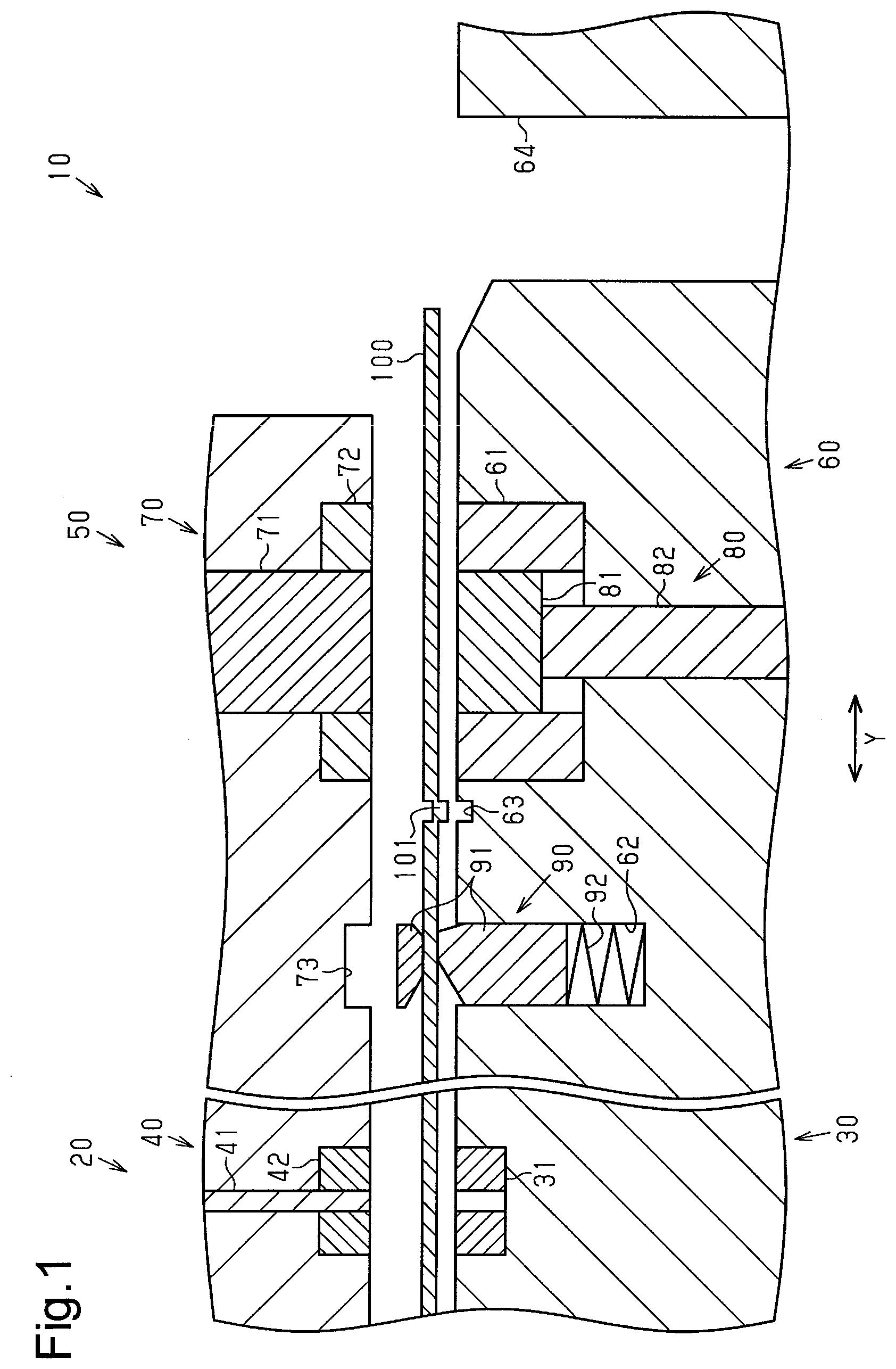
[0010] FIG. 1 is a cross-sectional view of a stamping method and a stamping apparatus according to one embodiment, illustrating the structure of the stamping apparatus.
[0011] FIG. 2 is a plan view of a workpiece illustrating protrusions of the embodiment together with a punch-out portion.
[0012] FIG. 3 is a cross-sectional view of the stamping method of the embodiment, illustrating a state in which the workpiece has been conveyed to a protrusion providing mechanism.
[0013] FIG. 4 is a cross-sectional view of the stamping method of the embodiment, illustrating a state in which protrusions have been provided on the workpiece.
[0014] FIG. 5 is a cross-sectional view of the stamping method of the embodiment, illustrating a state in which the workpiece has been conveyed to a punch-out mechanism.
[0015] FIG. 6 is a cross-sectional view of the stamping method of the embodiment, illustrating a state in which the workpiece is held by a second lower die assembly and a second upper die assembly.
[0016] FIG. 7 is a cross-sectional view of the stamping method of the embodiment, illustrating a state in which a product has been punched out from the workpiece by a second punch.
[0017] FIG. 8 is a cross-sectional view of the stamping method of the embodiment, illustrating a state in which the product is lifted by a back pressure portion.
[0018] FIG. 9 is a cross-sectional view of the stamping method of the embodiment, illustrating a state in which the product is being pushed toward an ejection portion by protrusions.
[0019] FIG. 10 is a plan view of a workpiece illustrating a protrusion of a modification together with a punch-out portion.
[0020] Throughout the drawings and the detailed description, the same reference numerals refer to the same elements. The drawings may not be to scale, and the relative size, proportions, and depiction of elements in the drawings may be exaggerated for clarity, illustration, and convenience.
DETAILED DESCRIPTION
[0021] This description provides a comprehensive understanding of the methods, apparatuses, and/or systems described. Modifications and equivalents of the methods, apparatuses, and/or systems described are apparent to one of ordinary skill in the art. Sequences of operations are exemplary, and may be changed as apparent to one of ordinary skill in the art, with the exception of operations necessarily occurring in a certain order. Descriptions of functions and constructions that are well known to one of ordinary skill in the art may be omitted.
[0022] Exemplary embodiments may have different forms, and are not limited to the examples described. However, the examples described are thorough and complete, and convey the full scope of the disclosure to one of ordinary skill in the art.
[0023] A stamping method and a stamping apparatus 10 according to an embodiment will be described with reference to FIGS. 1 to 9.
[0024] The stamping apparatus 10 of the present embodiment is employed in a progressive stamping apparatus, which is configured to subject a plate-shaped workpiece, which is intermittently conveyed by a feeder (not shown), to multiple steps such as a piercing step and a punching-out step in a single apparatus.
[0025] As shown in FIG. 1, the stamping apparatus 10 is designed to punch out a product P from a workpiece 100, which is conveyed from left to right in FIG. 1. The product P of the present embodiment is a gear having teeth on the outer circumference. Hereinafter, the conveying direction of the workpiece 100 will be simply referred to as conveying direction Y, and the upstream side and the downstream side of the conveying direction Y will be referred to as the upstream side and the downstream side. A direction that is orthogonal to both the conveying direction Y and the vertical direction will be referred to as a width direction.
[0026] The stamping apparatus 10 includes a protrusion providing mechanism 20, a punch-out mechanism 50, and a displacing mechanism 90. The protrusion providing mechanism 20 is configured to provide downward protrusions 101 in the workpiece 100. The punch-out mechanism 50 is provided on the downstream side of the protrusion providing mechanism 20 and is configured to punch out the product P from the workpiece 100. The displacing mechanism 90 is configured to displace the workpiece 100 upward.
[0027] First, the protrusion providing mechanism 20 will be described.
[0028] The protrusion providing mechanism 20 includes a first lower die assembly 30, which has two first dies 31, and a first upper die assembly 40, which has two first punches 41. The conveyed workpiece 100 is placed on the first dies 31. The first punches 41 are arranged to approach and move away from the first dies 31 in the vertical direction. The first upper die assembly 40 is arranged to approach and move away from the first lower die assembly 30.
[0029] Each first punch 41 has a circular shape in the cross section orthogonal to the vertical direction.
[0030] The first upper die assembly 40 has recesses in the lower surface. The recesses receive two first holding members 42, which hold the workpiece 100 against the first dies 31. The first punches 41 are arranged to be projected from and retracted into the lower surfaces of the first holding members 42.
[0031] When the first punches 41 are lowered toward the first dies 31, two protrusions 101 each having a circular cross section are provided in the workpiece 100. The protrusions 101 of the present embodiment are dowels that are protruded downward by performing half-blanking on the workpiece 100. The protruding amount of the protrusions 101 from the lower surface of the workpiece 100 (hereinafter, simply referred to as the protruding amount) is smaller than the thickness of the workpiece 100.
[0032] The two first dies 31 are spaced apart from each other in a width direction X. The two first punches 41 and the two holding members 42 correspond to the two first dies 31.
[0033] Accordingly, the two protrusions 101 of the workpiece 100 are spaced apart from each other in the width direction X as shown in FIG. 2. The workpiece 100 has a punch-out portion 102, from which the product P will be punched out. The protrusions 101 are provided in a part that is on the upstream side of the punch-out portion 102 and aligned with the punch-out portion 102. The protrusions 101 are provided at positions that correspond to the opposite sides of the punch-out portion 102 in the width direction X. The protrusions 101 are provided in a feed bridge of the workpiece 100, which connects the punch-out portion 102 to the subsequent punch-out portion 102, which will be punched out after the first punch-out portion 102.
[0034] In this manner, the workpiece 100, on which the protrusions 101 are provided, is conveyed to the punch-out mechanism 50, which is located on the downstream side of the protrusion providing mechanism 20.
[0035] The punch-out mechanism 50 will now be described.
[0036] As shown in FIG. 1, the punch-out mechanism 50 includes a second lower die assembly 60, which has a second die 61, and a second upper die assembly 70, which has a second punch 71. The workpiece 100 is placed on the second die 61. The second punch 71 is arranged to approach and move away from the second die 61. The second upper die assembly 70 is arranged to approach and move away from the second lower die assembly 60. The second die 61 has a gear forming portion on the inner circumferential surface, and the second punch 71 has a gear forming portion on the outer circumferential surface. The second die 61 corresponds to the die of the present disclosure. The second punch 71 corresponds to the punch of the present disclosure.
[0037] The second die 61 incorporates a back pressure portion 80, which is urged toward the second punch 71 to apply a back pressure to the workpiece 100. The back pressure portion 80 includes a pushing member 81, which pushes the workpiece 100 from below, and an urging portion 82, which urges the pushing member 81 upward. In a state in which the pushing member 81 is not pushed by the second punch 71, the upper surface of the pushing member 81 and the upper surface of the second die 61 are flush with each other. The pushing member 81 has a gear forming portion on the outer circumferential surface.
[0038] The urging portion 82 of the present embodiment may be a gas cylinder unit that includes, for example, a cylinder and a piston rod that is reciprocal in the cylinder.
[0039] The second upper die assembly 70 has a recess in the lower surface. The recess receives a second holding member 72, which holds the workpiece 100 against the second die 61. The second punch 71 is arranged to be projected from and retracted into the lower surface of the second holding member 72.
[0040] The displacing mechanism 90 will now be described.
[0041] The displacing mechanism 90 is provided in a part of the second lower die assembly 60 that is on the upstream side of the second die 61, and is configured to displace the workpiece 100 upward with respect to the second die 61. Specifically, the displacing mechanism 90 is provided in an accommodating portion 62, which is provided in the second lower die assembly 60 and is open upward. The displacing mechanism 90 includes a clamp portion 91, which clamps the workpiece 100 in the vertical direction, and a compression spring 92, which is provided in the accommodating portion 62 to urge the clamp portion 91 upward.
[0042] Escape portions 63, which open upward, are provided in a part of the upper surface of the second lower die assembly 60 that is between the displacing mechanism 90 and the second die 61 in the conveying direction Y. The escape portions 63 are designed to allow the protrusions 101 of the workpiece 100 to escape into when the workpiece 100 is punched out, such that the workpiece 100 is placed along the upper surface of the second lower die assembly 60. The depth of the escape portions 63 is greater than the protruding amount of the protrusions 101.
[0043] An accommodating portion 73, which opens downward, is provided in a part of the lower surface of the second upper die assembly 70 that is on the upstream side of the second holding member 72. The accommodating portion 73 is designed to accommodate the upper part of the clamp portion 91 of the displacing mechanism 90 when the second lower die assembly 60 and the second upper die assembly 70 are clamped.
[0044] The second lower die assembly 60 has an ejection portion 64 in a part that is on the downstream side of the second die 61. The ejection portion 64 ejects the product P, which has been punched out by the second punch 71, to the outside of the second lower die assembly 60. The ejection portion 64 is a through-hole that has a diameter larger than the diameter of the product P and extends vertically through the second lower die assembly 60.
[0045] The stamping method of punching out the product P from the workpiece 100 using the stamping apparatus 10 will now be described.
[0046] First, as shown in FIG. 3, the workpiece 100 is conveyed to the protrusion providing mechanism 20 by a feeder, such that the workpiece 100 is placed on the first dies 31.
[0047] As shown in FIG. 4, the workpiece 100 is held between the first lower die assembly 30 and the first upper die assembly 40. Then, the first punches 41 are lowered to perform half-blanking on the workpiece 100 to provide the protrusions 101 (protrusion providing step).
[0048] As shown in FIG. 5, the workpiece 100, on which the protrusions 101 are provided, is conveyed to the punch-out mechanism 50. At this time, the workpiece 100 is conveyed such that the protrusions 101 are located at positions directly above the escape portions 63 of the second lower die assembly 60.
[0049] Next, the second upper die assembly 70 is lowered as shown in FIG. 6, so that the workpiece 100 is held by the second lower die assembly 60 and the second upper die assembly 70. At this time, the upper part of the clamp portion 91 of the displacing mechanism 90 is accommodated in the accommodating portion 73 of the second upper die assembly 70. The clamp portion 91 is pushed by the second upper die assembly 70 so as to be displaced downward. Also, the protrusions 101 of the workpiece 100 are accommodated in the escape portions 63 of the second lower die assembly 60. Accordingly, the workpiece 100 is placed on the second die 61 while being in accordance with the upper surface of the second lower die assembly 60.
[0050] Next, the second punch 71 is lowered as shown in FIG. 7, so that the second die 61, the second punch 71, and the back pressure portion 80 punch out the product P from the workpiece 100 (punching-out step).
[0051] Next, the second punch 71 is moved away from the second die 61 and the second upper die assembly 70 is lifted as shown in FIG. 8. At the same time, the displacing mechanism 90 displaces the workpiece 100, from which the product P has been punched out, upward with respect to the second die 61 (displacing step).
[0052] The displacing mechanism 90 displaces the workpiece 100 upward to a position where the protrusions 101 are aligned with the product P in the conveying direction Y. The amount by which the workpiece 100 is displaced from the upper surface of the second lower die assembly 60 by the displacing mechanism 90 is greater than the thickness of the product P and smaller than the sum of the thickness of the product P and the protruding amount of the protrusions 101. In the present embodiment, the workpiece 100 is displaced upward to a position where a small clearance exists between the lower surface of the workpiece 100 and the upper surface of the product P. Thus, the displacement amount is the sum of the thickness of the product P and the clearance.
[0053] The product P remains on the pushing member 81 in a state in which the workpiece 100 has been displaced upward by the displacing mechanism 90.
[0054] When the workpiece 100 is conveyed further as shown in FIG. 9, the protrusions 101 are displaced downstream in the conveying direction together with the workpiece 100. The protrusions 101 are caused to abut against the upstream end of the product P, so that the product P is pushed downstream. Accordingly, the product P is ejected to the outside through the ejection portion 64 (ejection step).
[0055] As described above, the product P is produced from the workpiece 100.
[0056] The operation and advantages of the present embodiment will now be described.
[0057] (1) In the punching-out step, the product P is punched out from the workpiece 100 by the second die 61, on which the conveyed workpiece 100 is placed, the second punch 71, which is arranged to approach and move away from the second die 61, and the back pressure portion 80, which is provided in the second die 61 and is urged toward the second punch 71 to apply a back pressure to the workpiece 100. In the displacement step, the workpiece 100 is displaced upward with respect to the second die 61 when the second punch 71 moves away from the second die 61. In the protrusion providing step, the protrusions 101, which protrude downward, are provided prior to the punching-out step. The protrusions 101 are located in a part that is on the upstream side in the conveying direction Y of the workpiece 100 of the punch-out portion 102, from which the product P will be punched out. The part is also aligned with the punch-out portion 102. In the ejection step, the protrusions 101, which are displaced downstream in the conveying direction Y together with the workpiece 100, push the product P downstream in the conveying direction Y, so that the product P is ejected to the outside.
[0058] With this method, the product P, which has been punched out by the second die 61, the second punch 71, and the back pressure portion 80, remains on the back pressure portion 80. The workpiece 100 is displaced upward with respect to the second die 61 when the second punch 71 moves away from the second die 61. With the above-described method, the protrusions 101, which protrude downward, are provided in the workpiece 100 before the product P is punched out. Accordingly, the product P on the back pressure portion 80 is pushed downstream in the conveying direction Y by the protrusions 101 as the workpiece 100 is conveyed, so that the product P is ejected to the outside. Since the above-described method ejects the product P to the outside by utilizing the conveyance of the workpiece 100, no additional devices for ejecting the product P to the outside are needed. The product P is ejected to the outside by a simple method.
[0059] In a case of a configuration that includes a device for ejecting products P to the outside, the ejection step of a product P is completed before the workpiece is conveyed for the punching-out step of the subsequent product P. This extends the manufacturing time by the amount of time corresponding to the ejection step of the product P.
[0060] In this regard, the above-described method ejects the product P as the workpiece 100 is conveyed before the subsequent product P is punched out. This shortens the time required for the stamping process. The productivity of the stamping process is thus improved.
[0061] (2) Half-blanking is performed on the workpiece 100 to provide the protrusions 101.
[0062] When, for example, magnets that are separate from the workpiece 100 are provided as protrusions on the lower surface of the workpiece 100, an operation for retrieving the magnets may be necessary.
[0063] In this regard, the above-described method does not require such an operation since the protrusions 101 are provided integrally with the workpiece 100. This improves the productivity of the stamping process.
[0064] (3) The protrusions 101 are provided at positions that correspond to the opposite sides of the punch-out portion 102 in the width direction X.
[0065] With this method, as the workpiece 100 is conveyed, the protrusions 101, which are provided at positions corresponding to the opposite sides in the width direction X of the punch-out portion 102, push the opposite sides in the width direction X of the product P. The product P is thus ejected in a reliable manner.
[0066] (4) The stamping apparatus 10 includes the punch-out mechanism 50, the protrusion providing mechanism 20, and the displacing mechanism 90. The punch-out mechanism 50 includes the second die 61, on which the conveyed workpiece 100 is placed, the second punch 71, which is arranged to approach and move away from the second die 61, and the back pressure portion 80, which is provided in the second die 61 and is urged toward the second punch 71 to apply a back pressure to the workpiece 100. The punch-out mechanism 50 is configured to punch out the product P from the workpiece 100 by using the second die 61, the second punch 71, and the back pressure portion 80. The protrusion providing mechanism 20 is configured to provide the protrusions 101, which protrude downward, in a part that is located on the upstream side in the conveying direction Y of the workpiece 100 of the punch-out portion 102 of the workpiece 100, from which the product P will be punched out. The part is aligned with the punch-out portion 102. The displacing mechanism 90 is configured to displace the workpiece 100 to a position where the protrusions 101 and the product P overlap with each other in the vertical direction when the second punch 71 moves away from the second die 61.
[0067] This configuration achieves an operational advantage similar to the above-described operational advantage (1).
[0068] The present embodiment may be modified as follows. The present embodiment and the following modifications can be combined as long as the combined modifications remain technically consistent with each other.
[0069] The ejection portion 64 may be a belt conveyor that conveys the product P to the outside.
[0070] The pushing member 81 may incorporate a lifter that is urged toward the second punch 71 and lifts the product P above the upper surface of the pushing member 81 in the displacement step. In this case, since the pushing member 81 is prevented from closely contacting the product P, the product P is easily ejected. At this time, the amount by which the workpiece 100 is displaced from the upper surface of the second lower die assembly 60 by the displacing mechanism 90 simply needs to be greater than the sum of the thickness of the product P and the protruding amount of the lifter from the upper surface of the second lower die assembly 60 and smaller than the sum of the thickness of the product P, the protruding amount of the lifter from the upper surface of the second lower die assembly 60, and the protruding amount of the protrusions 101.
[0071] Two or more displacing mechanisms 90 may be provided on the upstream side and the downstream side of the second die 61 as necessary.
[0072] The number, the shape, and the arrangement of the protrusions 101 may be changed in accordance with the shape of the product P as necessary. For example, as shown in FIG. 10, instead of multiple protrusions 101, a single protrusion 103, which extends along the circumferential direction of the punch-out portion 102 may be provided on the upstream side of the punch-out portion 102 and at a position aligned with the center in the width direction X of the punch-out portion 102.
[0073] The protrusions are not limited to the ones that are provided by performing half-blanking on the workpiece 100. The protrusions may be provided through burring. The protrusions may be provided on the workpiece 100 by attaching magnets on the lower surface of the workpiece 100.
[0074] The range in application of the stamping apparatus 10 is not limited to the product P, which has gear teeth on the outer circumference. The stamping apparatus 10 of the present embodiment can be employed in producing products having various shapes as long as those are punched out of a plate-shaped workpiece.
[0075] Various changes in form and details may be made to the examples above without departing from the spirit and scope of the claims and their equivalents. The examples are for the sake of description only, and not for purposes of limitation. Descriptions of features in each example are to be considered as being applicable to similar features or aspects in other examples. Suitable results may be achieved if sequences are performed in a different order, and/or if components in a described system, architecture, device, or circuit are combined differently, and/or replaced or supplemented by other components or their equivalents. The scope of the disclosure is not defined by the detailed description, but by the claims and their equivalents. All variations within the scope of the claims and their equivalents are included in the disclosure.
* * * * *
D00000
D00001
D00002
D00003
D00004
D00005
D00006
XML
uspto.report is an independent third-party trademark research tool that is not affiliated, endorsed, or sponsored by the United States Patent and Trademark Office (USPTO) or any other governmental organization. The information provided by uspto.report is based on publicly available data at the time of writing and is intended for informational purposes only.
While we strive to provide accurate and up-to-date information, we do not guarantee the accuracy, completeness, reliability, or suitability of the information displayed on this site. The use of this site is at your own risk. Any reliance you place on such information is therefore strictly at your own risk.
All official trademark data, including owner information, should be verified by visiting the official USPTO website at www.uspto.gov. This site is not intended to replace professional legal advice and should not be used as a substitute for consulting with a legal professional who is knowledgeable about trademark law.