Perforated Insole with Dynamic Support Layer
Purcell; Wayne
U.S. patent application number 16/351070 was filed with the patent office on 2020-09-17 for perforated insole with dynamic support layer. The applicant listed for this patent is Wayne Purcell. Invention is credited to Wayne Purcell.
| Application Number | 20200288811 16/351070 |
| Document ID | / |
| Family ID | 1000003957908 |
| Filed Date | 2020-09-17 |


| United States Patent Application | 20200288811 |
| Kind Code | A1 |
| Purcell; Wayne | September 17, 2020 |
Perforated Insole with Dynamic Support Layer
Abstract
An insole installed on top of existing footwear with a sealed chamber extending across the plantar surface of the foot filled with a fluid that can traverse across the chamber in response to pressure caused by a weight shift by the wearer. The movement of the fluid (which may be a liquid, gas, or gel) serves to massage the foot muscles and tendons, release toxins, and increase circulation. The chamber may also have restrictions or unique shapes to guide the fluid for maximum effectiveness.
| Inventors: | Purcell; Wayne; (Avon, IN) | ||||||||||
| Applicant: |
|
||||||||||
|---|---|---|---|---|---|---|---|---|---|---|---|
| Family ID: | 1000003957908 | ||||||||||
| Appl. No.: | 16/351070 | ||||||||||
| Filed: | March 12, 2019 |
| Current U.S. Class: | 1/1 |
| Current CPC Class: | A43B 17/026 20130101; A43B 17/03 20130101; A43B 17/006 20130101 |
| International Class: | A43B 17/02 20060101 A43B017/02; A43B 17/00 20060101 A43B017/00; A43B 17/03 20060101 A43B017/03 |
Claims
1. An insole for insertion into footwear between the plantar surface of the wearer's foot and the inner surface of a shoe, said insole comprising: (a) a base material having a peripheral edge defining a toe portion, a heel portion and an intermediate arch portion, said base material being fabricated from a flexible material having opposite first and second generally planar surfaces; (b) a secondary material peripherally joined and sealed to said first surface and extending between the heel portion and intermediate arch portion to form an enclosed cavity between the base material and secondary material; (c) wherein said cavity contains a fluid substance configured to traverse said cavity in response to changes in the distribution of pressure along the plantar surface of the wearer's foot; and (d) a plurality of restrictions positioned within the cavity between the distal end of the arch portion and the proximal edge of the heel portion which restricts the movement of said fluid substance.
2. The insole of claim 1 wherein said base material further includes at least one series of perforations extending through the base material which form a curve inset from and generally conforming to the peripheral edge of said toe portion and with ends terminating at the medial and lateral peripheral edge of the intermediate arch portion.
3. The insole of claim 2 wherein said curve defined by the perforations extending through the base materials also comprises a series of secondary perforations which do not extend through the base material.
4. The insole of claim 3 wherein said base material further includes a generally elliptically shaped opening extending through the first and second surface with a diameter greater than 5 mm and corresponding to a position between the first and second phalanges of the wearer's foot.
5. The insole of claim 3 wherein said base material further includes a generally elliptical shaped opening with a diameter greater than 5 mm, extending between the first and second planar surface, and generally positioned in said toe portion corresponding between the first and second phalanges of the wearer's foot.
6. The insole of claim 3 wherein said base material further includes a third series of perforations that are configured in a generally elliptical shape with a diameter greater than 5 mm, extending between the first and second planar surface, and generally positioned in said toe portion corresponding between the first and second phalanges of the wearer's foot.
7. The insole of claim 2 wherein said perforations in said base material are die cut.
8. The insole of claim 1 wherein said fluid substance is air.
9. The insole of claim 1 wherein said fluid substance is a gel.
10. An insole for insertion into footwear between the plantar surface of the wearer's foot and the inner surface of a shoe, said insole comprising: a base material which includes (a) a peripheral edge defining a toe portion, a heel portion and an intermediate arch portion, (b) fabricated from a flexible material having opposite first and second generally planar surfaces; and (c) a first series of perforations positioned along a curve which is inset from and generally conforming to the peripheral edge of said toe portion and with ends terminating at the medial and lateral peripheral edge of the intermediate arch portion;
11. The insole of claim 10 wherein a second series of perforations positioned along a curve is inset from and generally conforming to the first series of perforations opposite the peripheral edge of said toe portion and with ends terminating at the medial and lateral peripheral edge of the intermediate arch portion.
12. The insole of claim 11 wherein said first and second perforations each comprise of a polarity of alternating first and second depths wherein the first depth passes through the first and second planar surfaces of the base material and the second depth passes from the first planar surface to a point within the base material between the first planar surface and the second planar surface.
13. The insole of claim 12 wherein said perforations in said base material are die cut.
14. The insole of claim 13 wherein said base material further includes a third series of perforations that are configured in a generally elliptical shape with a diameter greater than 5 mm, extending between the first and second planar surface, and generally positioned in said toe portion corresponding between the first and second phalanges of the wearer's foot.
15. An insole for insertion into footwear between the plantar surface of the wearer's foot and the inner surface of a shoe, said insole comprising: (a) a base material having a peripheral edge defining a toe portion, a heel portion and an intermediate arch portion, said base being fabricated from a flexible material having opposite first and second generally planar surfaces; (b) a secondary material peripherally joined and sealed to said first surface and extending between the heel portion and intermediate arch portion to form an enclosed cavity between the base material and secondary material; (c) wherein said cavity contains a fluid substance configured to traverse said cavity in response to changes in the distribution of pressure along the plantar surface of the wearer's foot; and (d) wherein said base material further includes a series of perforations that are configured in a generally elliptical shape with a diameter greater than 5 mm, extending between the first and second planar surface, and generally positioned in said toe portion corresponding between the first and second phalanges of the wearer's foot.
16. The insole of claim 15 wherein said perforations in said base material are die cut.
17. The insole of claim 16 wherein said fluid substance is a gas.
18. The insole of claim 16 wherein said fluid substance is a liquid.
19. The insole of claim 16 wherein said fluid substance is a gel.
Description
CROSS-REFERENCE TO RELATED APPLICATION
[0001] Original Non-Provisional Application
BACKGROUND
[0002] The benefits of wearing insoles are well known in the fields of sports medicine and health sciences. There are a number of common foot ailments which may be associated with either a particular lifestyle activity or a pre-existing medical condition. Runners, for instance, often suffer from plantar fasciitis, wherein the band of tissue between the toes and the heel become tight and tear, while those living and coping with diabetic neuropathy require additional stimulation across the base of the foot to increase circulation. To address these conditions people often seek out therapeutic massage to encourage oxygenation, venous return, and increased lymphatic return in order to relieve pain and reduce fatigue.
[0003] Use of an insole designed to massage and stimulate the tissues of the foot can provide immediate relief as well as long-term benefits in addressing these issues. A dynamic insole is one which massages the foot by transferring an internal fluid across the plantar surface of the foot in response to changing pressures produced when the wearer shifts their weight.
[0004] During physical activity an insole also provides protection to the foot and throughout the skeletal system by absorbing shock and pressure endured when standing for long periods of time, walking, or running. In the case of a dynamic insole, the protection is further bolstered, when compared to a traditional foam insole, as the internal fluid is able to rapidly move across the arch in order to absorb and disperse the force of the impact across a larger area of the foot.
[0005] A study done by The Ohio State University in 2018 quantified the benefits of a dynamic insole. The purpose of the research was to assess the effects of different insoles configurations (i.e., no additional insole, a static insole, and a dynamic insole) on the measured tibial acceleration while walking while wearing athletic shoes and while wearing work boots. Table 1 summarizes the measured acceleration while walking across the various insoles and shoe type.
TABLE-US-00001 TABLE 1 Tibial accelerations as a function of insole and shoe type No Additional Insole Static Insole Dynamic Insole Athletic Shoe 29.2 (m/s.sup.2) 23.6 (m/s.sup.2) 22.3 (m/s.sup.2) Work Boot 22.5 (m/s.sup.2) 19.9 (m/s.sup.2) 18.4 (m/s.sup.2)
The complete results were published as "Quantifying the effectiveness of static and dynamic insoles in reducing the tibial shock experienced during walking" (2019, Lavender et al.)
SUMMARY OF THE INVENTION
[0006] The present invention is a therapeutic insole which may be installed by the user on top of the existing insole of the footwear. The insole is designed with a sealed chamber which may extend across the toe, arch, or heel portion of the foot--or across any combination therein. This chamber is filled with a fluid substance that can traverse across the chamber in response to changes in pressure caused by a weight shift by the wearer. The fluid may consist of any number of materials including gas, liquid, or gel-like substance. The movement of the fluid serves to massage the foot muscles and tendons, promote the release of toxins, and encourage circulation. The chamber may also have areas with restrictions or unique shapes which restrict and guide the fluid for maximum effectiveness.
[0007] As each foot is unique, a retailer may be challenged to maintain shelf space to accommodate the large variety of products. The insole needs to be personally matched not only to match the user's requirements to their different activities or support level but also to the size and shape of each foot. Herein, the present invention also discloses an apparatus and method for adjusting the size and changing features without the use of tools, thus allowing the retailer to carry a limited number of products while accommodating a broad span of consumer needs.
BRIEF DESCRIPTION OF THE DRAWINGS
[0008] FIG. 1. FIG. 1 shows an upper isometric view of the therapeutic insole.
[0009] FIG. 2. FIG. 2 shows a top view of the insole.
[0010] FIG. 3. FIG. 3 shows a bottom view of the insole.
[0011] FIG. 4. FIG. 4 shows a lateral cross-section of the insole with inner fluid chambers.
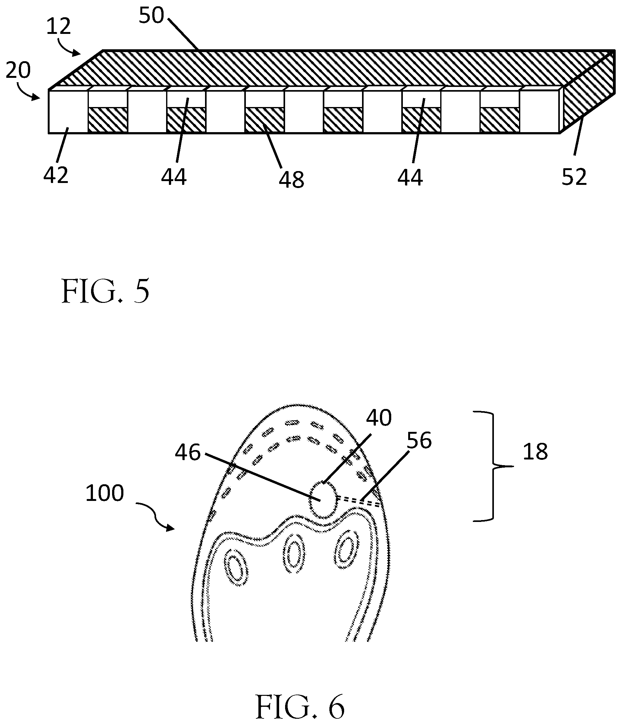
[0012] FIG. 5. FIG. 5 shows a side cross-section of the base layer perforation.
[0013] FIG. 6. FIG. 6 shows a top view of the toe area of the insole.
DETAILED DESCRIPTION OF THE INVENTION
[0014] Any activity where a person is on their feet for a length of time can result in foot pain or fatigue. More stressful activities, such as running, can cause impact injuries which directly affect the foot and transfer throughout joints of the skeletal system. The therapeutic insole 100 disclosed employs a dynamic fluid layer 26 to provide both cushion to minimize impact and immediate therapy to the plantar tissues of the foot. Furthermore, the therapeutic insole 100 works by stimulating the muscles under the foot and promoting circulation deep into the toes--critical to those living and coping with diabetic neuropathy. This increase in circulation provides a natural healing approach while soothing damaged nerves and stimulating muscles. Users who use such an insole report impressive improvements in comfort and pain management.
[0015] FIG. 1 shows an isometric view of the therapeutic insole 100 designed to be placed between the user's plantar surface of the foot and the corresponding insole surface of the user's footwear. In the preferred embodiment, the insole 100 is flexible relatively thin allowing it to be placed directly on top of any existing insole manufactured by the shoemaker. Alternatively, a thicker therapeutic insole 100 may be used as a replacement for the existing insole by the user or integrated by the original shoe manufacturer.
[0016] Sections of the therapeutic insole 100 are shown in FIG. 2 and may be described in terms corresponding to the user's foot including a distal toe section 18, an intermediate arch section 24, and a proximal heel section 14. In a similar methodology, around the peripheral edge of the insole there exists a medial edge 28 along the inside of the foot, a distal toe edge 30, a lateral edge 32 along the outside of the foot, and a proximal heel edge 34.
[0017] The base layer 12 is manufactured as a single piece and the bottom surface of the base layer 52 is shown in FIG. 3. The base layer 12 is generally planar and includes a toe section 18, intermediate arch 28, and heel section 30.
[0018] FIG. 4 shows a cross-section of the therapeutic insole 100 defined by line A-B constructed in FIG. 2. An upper layer 10 is positioned opposite the base layer 12 and sealed along the peripheral edges of the upper layer 36. In the preferred embodiment, the upper layer 10 is positioned and sealed on top of the base layer 12, however, an alternative embodiment could have the upper layer 10 positioned below the base layer 12. A chamber 38 is formed between the upper layer 10 and base layer 12 which is configured to contain a dynamic fluid 26. The dynamic fluid 26 may be a gas, liquid, or gel-like substance. The cross-section line A-B also bisects several of the divots in the chamber 38--which create restrictions 16 within the chamber 38 to divert, guide, or restrict the flow of the dynamic fluid 26.
[0019] Common materials used for the base layer 12 and the upper layer 10 may include closed cell foam, carbon fibers, elastic rubber, microfiber, or any other flexible material. In the preferred embodiment, the material for the base layer 12 and upper layer 10 is TPU, or thermoplastic polyurethane, which is extremely flexible and durable. The base layer 12 and upper layer 10 may also include a layer designed with a perspiration-absorbing system.
[0020] The upper layer 10 may be peripherally bound and sealed to the base layer 12 by means of ultrasonic welding, adhesives, stitching, or other mechanical means. The chamber 38 between the upper layer 10 and base layer 12 may reside exclusively in the heel section 14, intermediate arch section 24, or toe sections 18; or there may be a plurality of chambers 38 disposed across any combination of these sections. In the preferred embodiment, the chamber 38 extends across the distal end of the intermediate arch 24 and proximal edge of the heel section 14.
[0021] As shown in FIG. 2, a plurality of restrictions 16 guide or restrict the movement of the fluid substance 26 may be employed. In the preferred embodiment, the restrictions 16 are formed through ultrasonic welding of the upper layer 10 and the base layer 12.
[0022] The fluid substance 26 may comprise a liquid, gas, or gel or some combination therein. The fluid 26 is configured to traverse across the chamber 38. When the fluid 26 is a non-compressible material, such as a liquid or gel, the chamber 38 is not filled to the full capacity, so that the fluid 26 can transfer from one section to the other. When the fluid 26 is a gas, the pressure of the chamber 38 is configured such that it is capable of further compression under the weight of the user.
[0023] FIGS. 2 and FIGS. 3 provide a top view and bottom view respectively of the therapeutic insole 100. The toe section 18 of FIG. 3 and FIG. 4 illustrate a where a series of perforations 20 and 22 exist in the base layer 12 to enable the user to remove distal sections of the base layer 12 and adjust the overall size to fit within the user's shoe. The series of perforations 20 and 22 are arranged such that they generally form a curved line which are inset from the peripheral edge of the toe section 18 and extend outward to points of the medial peripheral edge 28 and lateral peripheral edge 32 near the intermediate arch section.
[0024] Similar series of perforated arrangements for sizing the toe section 18 may be made in the base material 12 of the heel section 14, wherein the perforations are inset from the proximal peripheral edge of the heel 34.
[0025] The following example is provided to illustrate a method of use whereby the user may possess an unaltered factory insole which is preconfigured to fit a large shoe sizes (such as men's 11-13). If the user requires a smaller size, he/she may tear at the first perforation 20 to accommodate a medium shoe size (such as men's 9-10.5), or tear at the second perforation 22 to accommodate a small shoe size (such as men's 7-8.5).
[0026] In the preferred embodiment, the series of perforations 20 and 22 are created in the base material through a die cutting process. It is common for perforated materials created by die cut methods to have a series of cuts regularly spaced across the face of the material which passes from the top side of the material and through the bottom side of the material. Perforations in a durable material, such as TPU, may be difficult to tear with the common method of perforation described. FIG. 5 illustrates an improvement from the common method for creating die-cut perforations. FIG. 5 shows a closeup of the perforation 20 in the base material 12 being die cut by an alternating series of deep cuts 42, wherein a section of the cutting edge of a die passes through the top side of the base material 50 and exits through the bottom side of the base material 52, and a series of shallow cuts 44 positioned between the deep cuts 42, wherein the cutting edge of the die passes through the top side of the base material 50 but does not exit through the bottom side of the base material 52. The combination of deep cuts 42 and shallow cuts 44 reduce the strength of the remaining attached base material 48 such that a user is able to quickly size the insole without the use of cutting tools, such as knives, scissors, etc. In the preferred embodiment, the deep cuts 42 and shallow cuts 44 exist along the same curve, alternating between deep 42 and shallow cuts, and wherein the deep cuts 42 and shallow cuts 44 in combination are continuous along the top side of the base material 50.
[0027] A unique feature of the therapeutic insole 100 is the ability for the user to configure the insole to function with thong sandals. Thong sandals are generally defined as having a strap, pipe, or post which passes between the big toe (first phalanges of the foot) and the second toe (second phalanges of the foot) to connect the midfoot strap and the sole of the shoe. In one embodiment the therapeutic insole 100 may be designed with a strap plug 46 formed within the base material 12 and generally corresponding between the first and second phalanges of the user to create an opening for the post of the thong sandal. The strap plug 46 may be removed by the user to create an opening within the base material 12 through which the thong strap may pass through. The strap plug 46 may preferably be elliptically shaped and have a diameter greater than 5 mm. Additionally, a strap insertion path 56 comprising a generally straight line connecting from the peripheral edge of the base material to the edge of the strap plug 46 and intended to be cut or torn by the user such that the user may position the therapeutic insole on the pre-existing factory insole without removing the thong strap from the sole of the shoe. The strap plug 46 and strap insertion path 56 may be formed as a perforation during the die cut process and may be formed by deep cuts 42, shallow cuts 44, or a combination therein as described within this specification.
[0028] The therapeutic insole 100 may further comprise an adhesive layer on the bottom of the base layer 52 to aid in positioning the therapeutic insole to the existing insole of the shoe. The adhesive layer is preferably configured as adhesive strip 54 with a non-adhesive release liner. Alternatively, the adhesive layer may cover the entirety of the bottom of the base layer 52 and wherein there are deep cut 44 perforations present in the bottom of the base layer 42, the adhesive layer may also be perforated.
* * * * *
D00000
D00001
D00002
D00003
XML
uspto.report is an independent third-party trademark research tool that is not affiliated, endorsed, or sponsored by the United States Patent and Trademark Office (USPTO) or any other governmental organization. The information provided by uspto.report is based on publicly available data at the time of writing and is intended for informational purposes only.
While we strive to provide accurate and up-to-date information, we do not guarantee the accuracy, completeness, reliability, or suitability of the information displayed on this site. The use of this site is at your own risk. Any reliance you place on such information is therefore strictly at your own risk.
All official trademark data, including owner information, should be verified by visiting the official USPTO website at www.uspto.gov. This site is not intended to replace professional legal advice and should not be used as a substitute for consulting with a legal professional who is knowledgeable about trademark law.