Garments And Other Items Incorporating Line-cutting Devices
Burrows; Janine ; et al.
U.S. patent application number 16/354631 was filed with the patent office on 2020-09-17 for garments and other items incorporating line-cutting devices. The applicant listed for this patent is Academy, Ltd.. Invention is credited to Michelle Broussard, Janine Burrows, Jenna Kerns, Nathan Kinney, Brian Krezinski.
| Application Number | 20200288690 16/354631 |
| Document ID | / |
| Family ID | 1000004003531 |
| Filed Date | 2020-09-17 |


View All Diagrams
| United States Patent Application | 20200288690 |
| Kind Code | A1 |
| Burrows; Janine ; et al. | September 17, 2020 |
GARMENTS AND OTHER ITEMS INCORPORATING LINE-CUTTING DEVICES
Abstract
Line cutters that may be incorporated into other items, such as garments or paddles. A garment that incorporates a line-cutting trim component allows a wearer to easily cut line or cord while fishing or engaging in other activities. The trim component includes a housing with an opening, and a line cutter partially extending into the opening. The trim component can be secured to the garment using a rivet, or sewn onto the garment. In another example, a paddle may incorporate a line cutter as part of a spring clip used to secure together the tubes of a multi-piece paddle.
| Inventors: | Burrows; Janine; (Katy, TX) ; Broussard; Michelle; (Katy, TX) ; Kerns; Jenna; (Katy, TX) ; Kinney; Nathan; (Katy, TX) ; Krezinski; Brian; (Katy, TX) | ||||||||||
| Applicant: |
|
||||||||||
|---|---|---|---|---|---|---|---|---|---|---|---|
| Family ID: | 1000004003531 | ||||||||||
| Appl. No.: | 16/354631 | ||||||||||
| Filed: | March 15, 2019 |
| Current U.S. Class: | 1/1 |
| Current CPC Class: | A45F 2005/023 20130101; A45F 5/02 20130101; A01K 97/00 20130101; A01K 97/24 20130101 |
| International Class: | A01K 97/00 20060101 A01K097/00; A45F 5/02 20060101 A45F005/02; A01K 97/24 20060101 A01K097/24 |
Claims
1. A garment, comprising: (a) a garment body; and (b) a garment trim secured to the garment body, the garment trim comprising: (i) a housing; (ii) an opening extending into the housing; and (iii) a line cutter at least partially extending into the opening.
2. The garment of claim 1, wherein the opening tapers as it extends into the body.
3. The garment of claim 1, wherein the opening is wedge shaped.
4. The garment of claim 2, wherein the housing comprises an outer surface facing away from the garment body, and inner surface facing towards the garment body, and a perimeter surface extending between the outer and inner surfaces.
5. The garment of claim 4, wherein the opening is formed in the outer, inner, and perimeter surfaces.
6. The garment of claim 4, wherein the garment trim is sewn to the garment body.
7. The garment of claim 6, wherein the garment trim is sewn to the garment body by a fabric loop sewn into the garment body, the fabric loop extending through an elongated opening extending through the garment trim.
8. The garment of claim 6, wherein the garment trim housing includes at least two holes where the garment trim is sewn to the garment body.
9. The garment of claim 8, wherein the line cutter is located between the two holes.
10. The garment of claim 4, wherein the garment trim is secured to the garment body by a button, tack or rivet.
11. The garment of claim 4, wherein the garment trim is a shank button configured to fit through a button hole in the garment.
12. The garment of claim 11, wherein the shank button comprises a post extending from the inner surface and through a portion of the garment body.
13. A garment, comprising: (a) a garment body, the garment body comprising a button hole; and (b) a shank button secured to the garment body, the shank button comprising: (i) a housing; (ii) an opening extending into the housing; (iii) a line cutter at least partially extending into the opening; and (iv) a shank configured to secure the shank button to a portion of the garment body; wherein the housing is sized to be passed through the button hole.
14. The garment of claim 13, wherein the shank button is configured to secure a first portion of the garment to a second portion of the garment.
15. The garment of claim 13, wherein the housing comprises a body of the shank button.
16. A paddle, the paddle comprising a head, the head comprising an opening extending into the head and a line cutter at least partially extending into the opening.
17. The paddle of claim 16, wherein the head extends out from a shaft of the paddle.
18. The paddle of claim 17, wherein the head is a portion of a spring clip configured to secure together two tubes of the shaft.
19. The paddle of claim 18, wherein the spring clip comprises a pair of spring arms, the head extending from one of the spring arms.
20. The paddle of claim 19, wherein, when the two tubes are secured together, the head of the spring clip extends through openings in the two tubes.
Description
RELATED FIELDS
[0001] Garments (such as shirts, pants, or shorts) and other items with incorporated line-cutting components.
BACKGROUND
[0002] When fishing and engaging in other activities, it can be helpful to have a line cutter that is easily accessible.
SUMMARY
[0003] This patent describes garments with incorporated line-cutting trim components that provide the garment's wearer with an easy way to cut fishing line and other types of line or string, when fishing and engaging in other activities where it is helpful to have easy access to a line cutter. This patent also describes other items with incorporated line-cutting components, such as a paddle.
BRIEF DESCRIPTION OF DRAWINGS
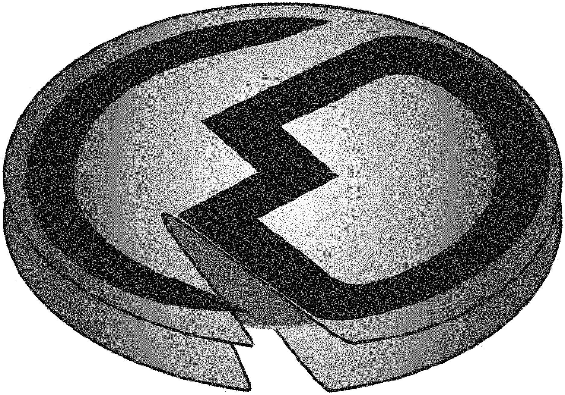
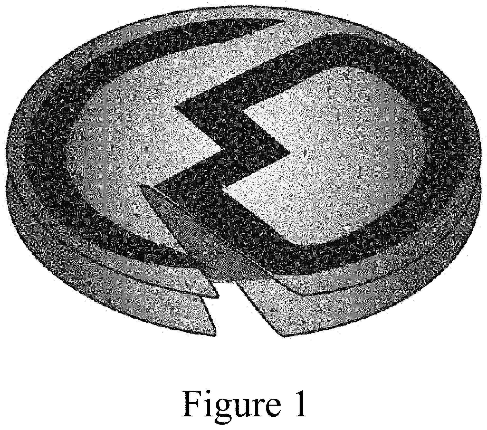
[0004] FIG. 1 shows an example of a line-cutting trim component, from a perspective, upper view.
[0005] FIG. 2 shows the line-cutting trim component of FIG. 1, from a perspective, lower view.
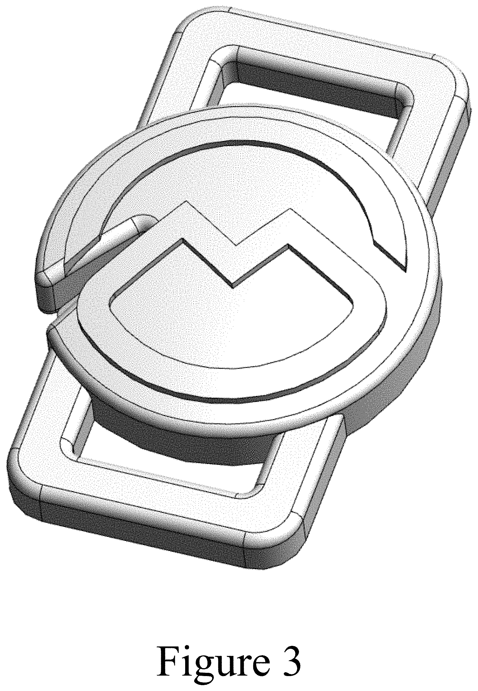
[0006] FIG. 3 shows another example of a line-cutting trim component, from a perspective, upper view.
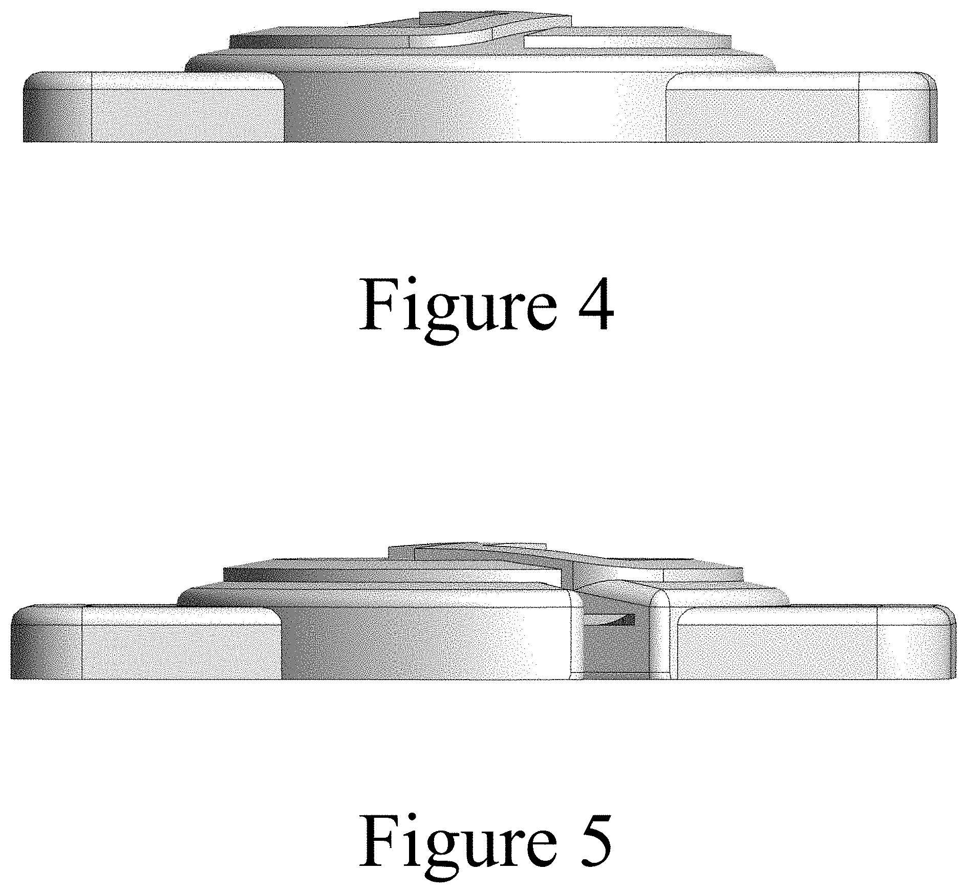
[0007] FIG. 4 shows the line-cutting trim component of FIG. 3, from a right side view.
[0008] FIG. 5 shows the line-cutting trim component of FIG. 3, from a left side view.
[0009] FIG. 6 shows the line-cutting trim component of FIG. 3, from a top side view.
[0010] FIG. 7 shows the line-cutting trim component of FIG. 3, from a bottom side view.
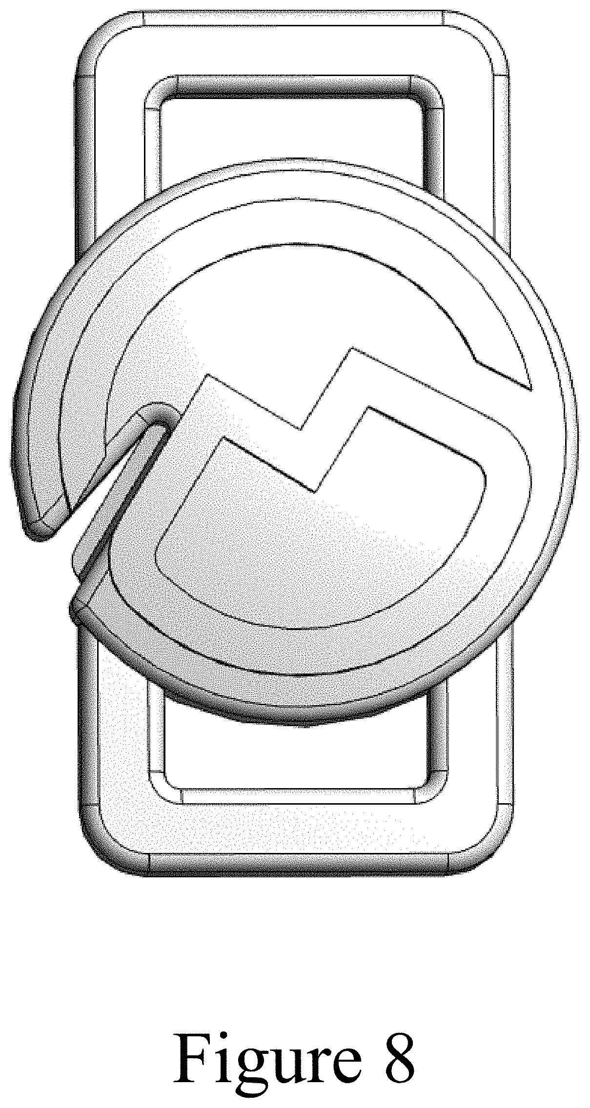
[0011] FIG. 8 shows the line-cutting trim component of FIG. 3, from a front view.
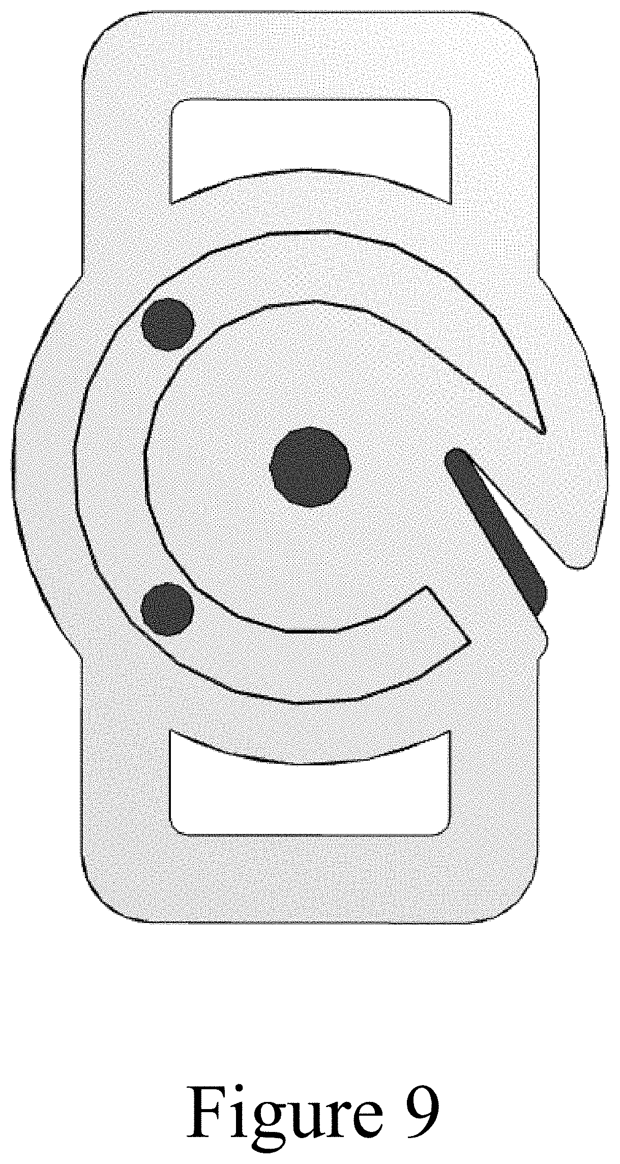
[0012] FIG. 9 shows the line-cutting trim component of FIG. 3, from a rear view.
[0013] FIG. 10 shows another example of a line-cutting trim component, from a perspective, upper view.
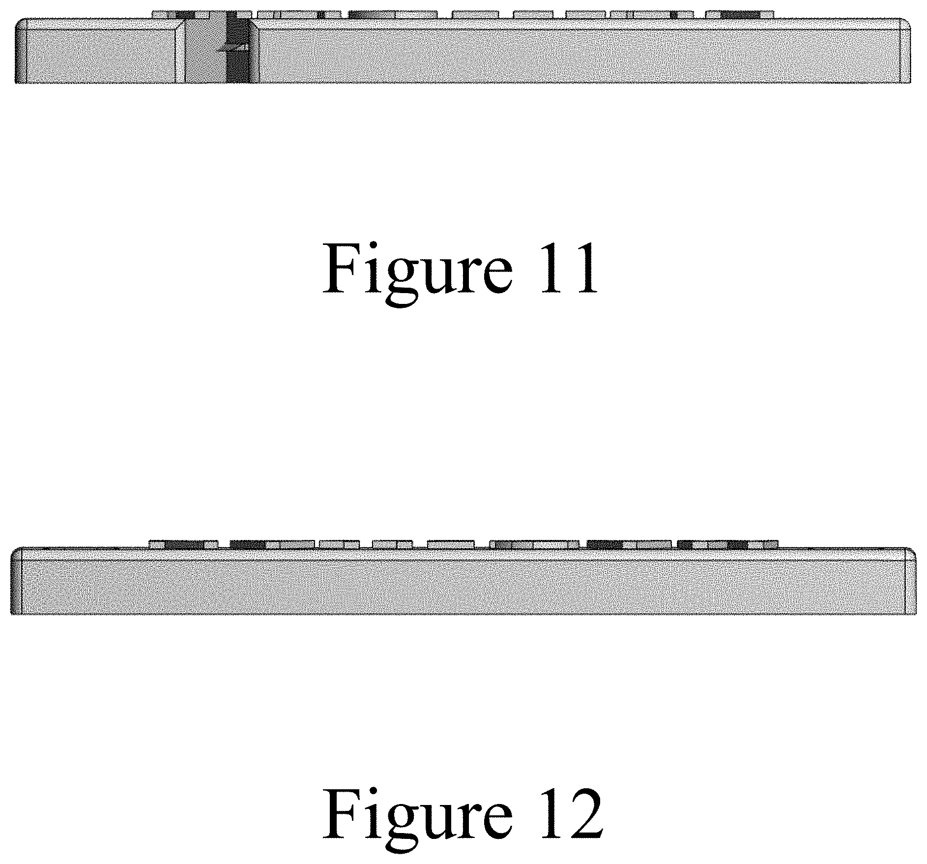
[0014] FIG. 11 shows the line-cutting trim component of FIG. 10, from a bottom side view.
[0015] FIG. 12 shows the line-cutting trim component of FIG. 10, from a top side view.
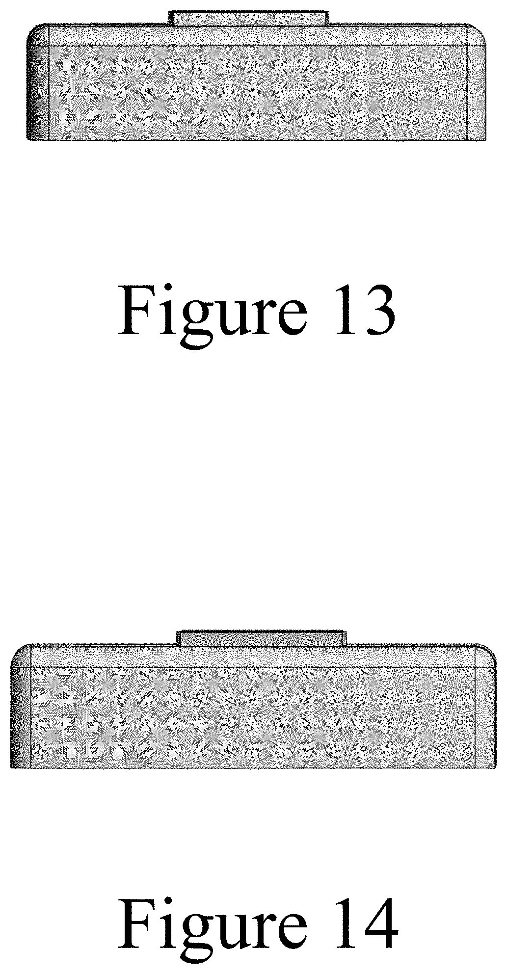
[0016] FIG. 13 shows the line-cutting trim component of FIG. 10, from a right side view.
[0017] FIG. 14 shows the line-cutting trim component of FIG. 10, from a left side view.
[0018] FIG. 15 shows the line-cutting trim component of FIG. 10, from a front view.
[0019] FIG. 16 shows the line-cutting trim component of FIG. 10, from a rear view.
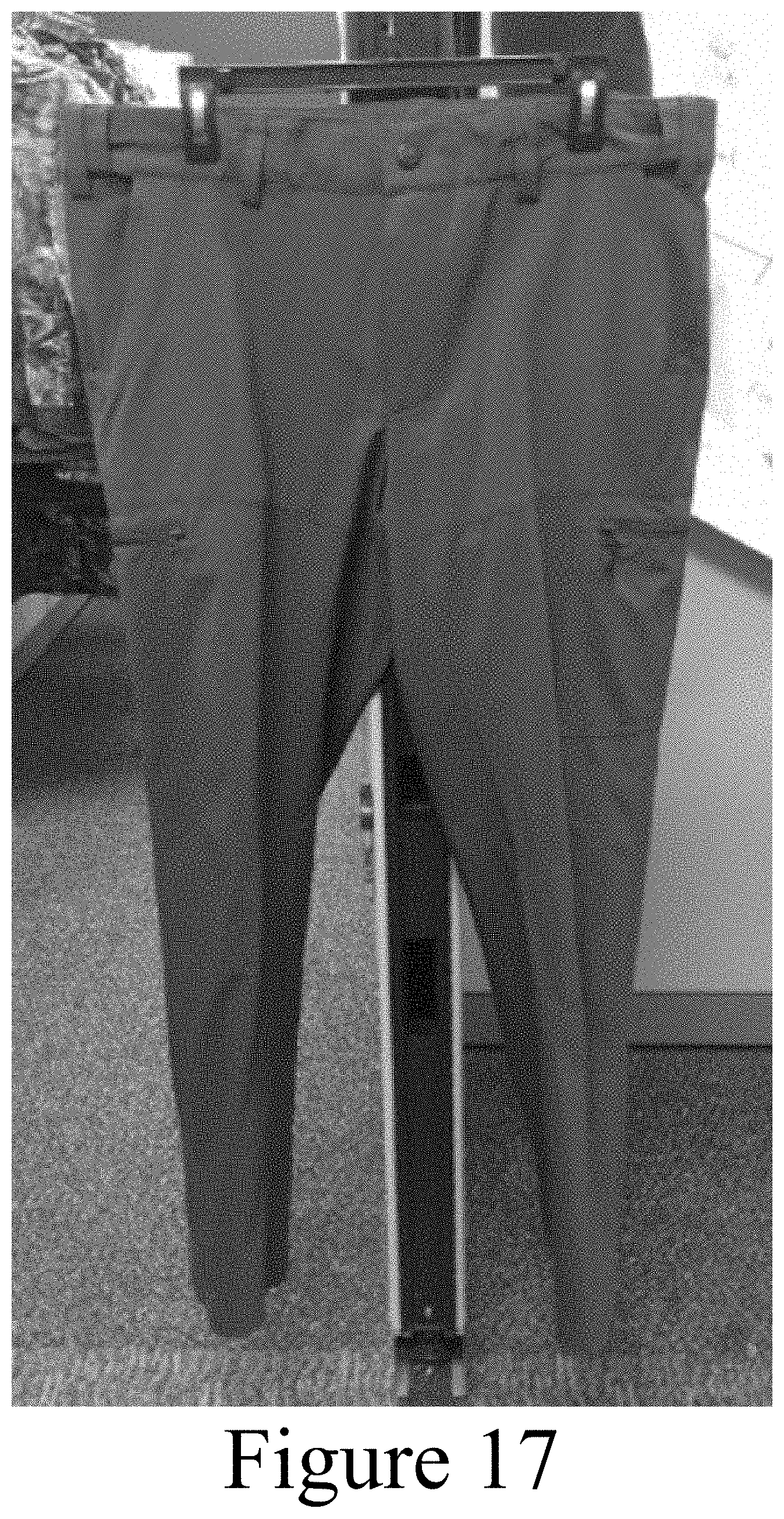
[0020] FIG. 17 shows pants incorporating a line-cutting trim component as a button.
[0021] FIG. 18 shows a close up of the line-cutting trim component of FIG. 17.
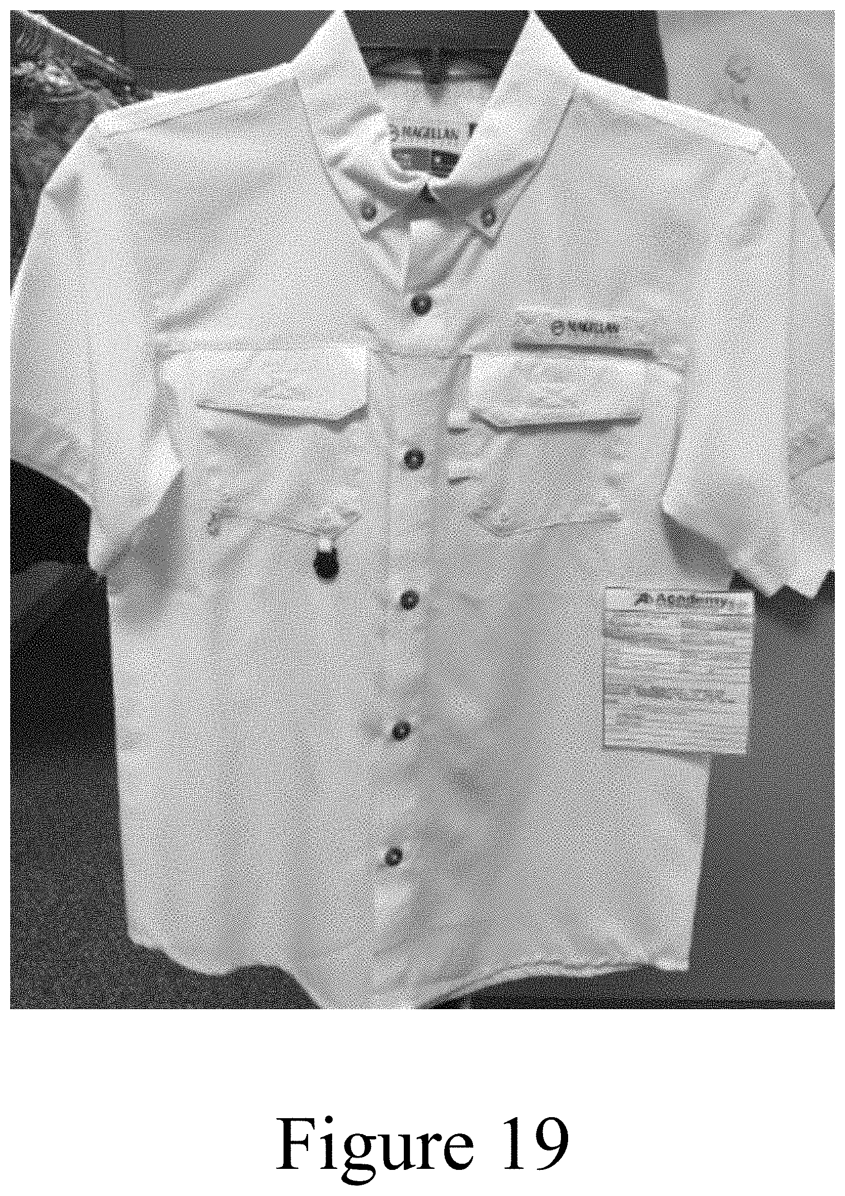
[0022] FIG. 19 shows a shirt incorporating a line-cutting trim component.
[0023] FIG. 20 shows a close up of the line-cutting trim component of FIG. 19.
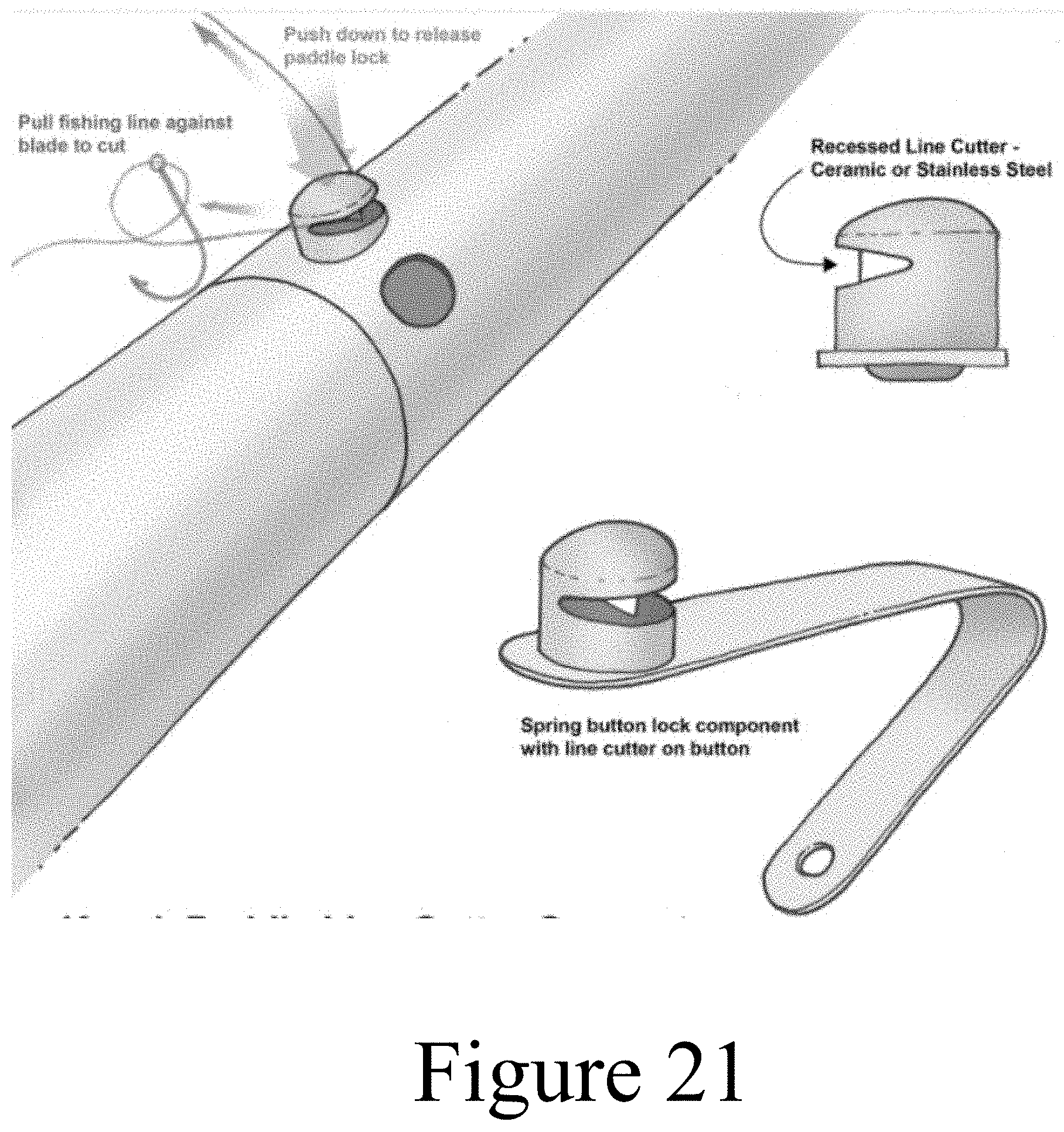
[0024] FIG. 21 shows a line-cutting component of a kayak paddle.
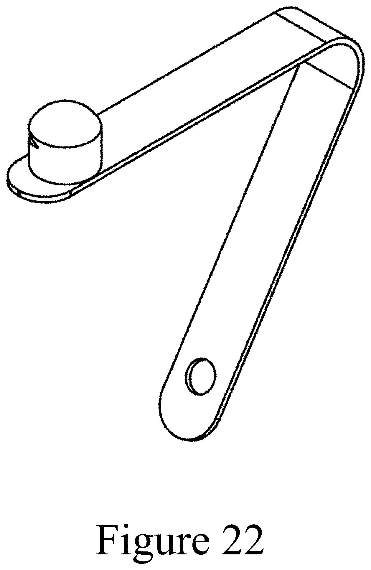
[0025] FIG. 22 shows a line-cutting component for a paddle, from a perspective view.
[0026] FIG. 23 shows the line-cutting component of FIG. 22, from a side view.
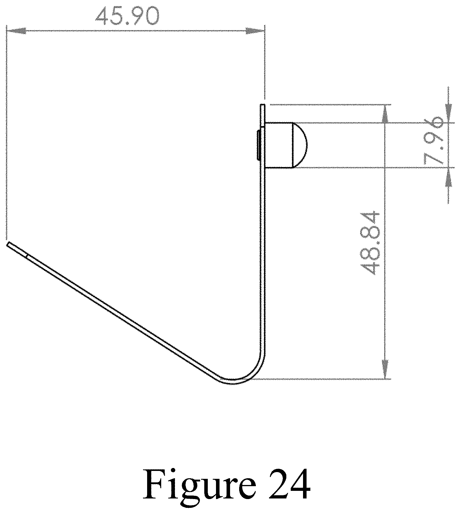
[0027] FIG. 24 shows the line-cutting component of FIG. 22, from another side view.
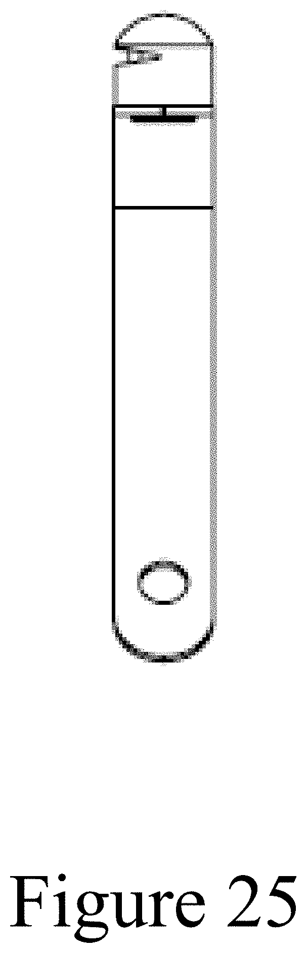
[0028] FIG. 25 shows the line-cutting component of FIG. 22, from another side view.
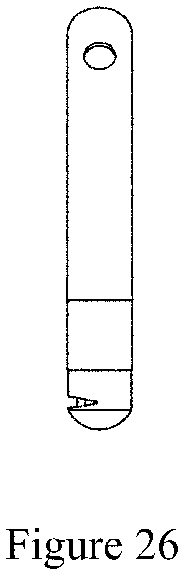
[0029] FIG. 26 shows the line-cutting component of FIG. 22, from another side view.
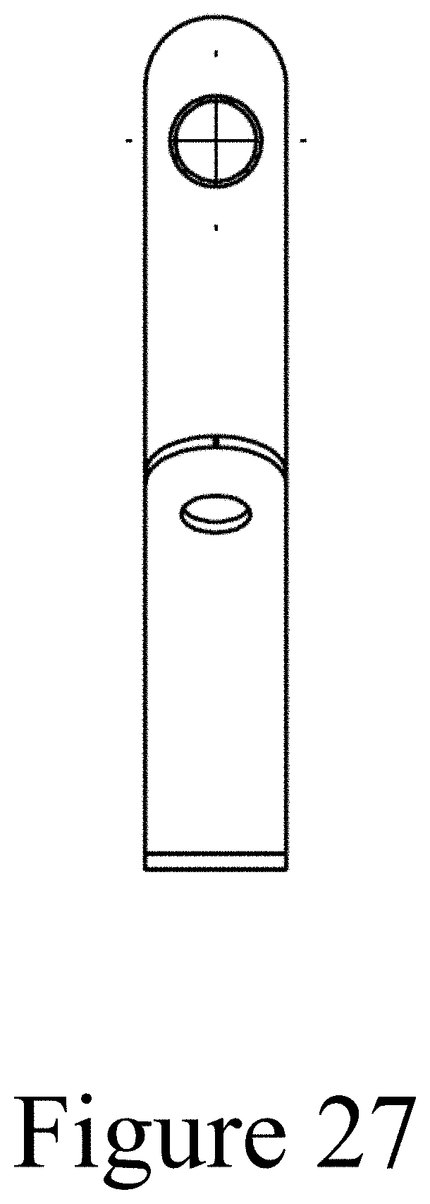
[0030] FIG. 27 shows the line-cutting component of FIG. 22, from another side view.
[0031] FIG. 28 shows a close up of the line cutter head of the line-cutting component of FIG. 22.
DETAILED DESCRIPTION OF DRAWINGS
[0032] FIGS. 1 and 2 show one example of a line-cutting trim component for a garment. As shown in these figures, the line-cutting trim component includes a housing, an opening extending into the housing, and a line cutter extending into a portion of the opening. In use, pulling or otherwise introducing under tension a line or cord (e.g., fishing line) into the opening will bring it into contact with the cutter, cutting the line or cord.
[0033] The opening in the housing tapers (in this example, as a wedge shape), which may assist in bringing the line or cord into the opening and into contact with the cutter. As shown in the example of FIGS. 1 and 2, the opening extends through the inner, outer, and perimeter surfaces of the housing.
[0034] In the example of FIGS. 1 and 2, the line-cutting trim is secured to the garment by passing the post on the inner surface (see FIG. 2) through a hole or opening in the garment body, and securing the component in place using a button tack or rivet.
[0035] FIGS. 3-9 and 10-16 show additional examples of line-cutting trim components. In these examples, the line-cutting trim is secured to the garment by sewing the component to the garment body, using the two holes extending through the component.
[0036] FIGS. 17-18 show an example of a line-cutting trim component incorporated into a pair of pants. In this example, the line-cutting trim component is a shank button (e.g., utilizing a post extending from the back of the button, such as shown in FIG. 2). As shown in FIG. 18, the shank button is sized and otherwise configured to fit through a button hole in the pants in order to button the pants.
[0037] FIGS. 19-20 show an example of a line-cutting trim component incorporated into a shirt. In this example, the shirt includes a fabric loop sewn into the shirt that loops through an opening of the trim component so that the line-cutting trim component hangs from the fabric loop. By securing the line-cutting trim component to the garment in this manner (or in other manners) the trim component can be swung or otherwise repositioned at least somewhat relative to the main body of the garment.
[0038] FIGS. 21-28 show examples of a line cutter incorporated into a spring clip, such as a spring clip that can be used to secure in a removable fashion the tubes of a multi-piece paddle (e.g. a kayak paddle, stand-up paddle board paddle, or other multi-piece paddle). As illustrated in FIG. 22, the spring clip includes a pair of spring arms 20, 22, an opening 24, and a pin head 26. The opening 24 may receive a fastener to secure the spring clip inside the tube of a paddle. The spring clip may be positioned inside of the paddle tube so that the pin head 26 of the spring clip passes through an opening in the paddle tube so that the pin head can be depressed into the opening and will spring back when released. When two paddle tubes are connected, the pin head may extend through openings in both tubes to connect them together, and may be depressed to allow one tube to be removed from another.
[0039] As shown in FIGS. 21 and 28, the pin head includes an opening and a cutter positioned within the opening, allowing the cutting of fishing line or other items in a similar fashion to the line-cutting trim components described above.
[0040] The line-cutting components shown in the figures may be made by injection molding a plastic housing around a metal cutter, or in any other desirable manner.
[0041] FIGS. 1-28 show non-limiting examples of our invention, and are not intended to limit the scope of this patent in any way. Changes and modifications can be made to the examples shown in FIGS. 1-28 and described above while still embodying our invention.
* * * * *
D00000
D00001
D00002
D00003
D00004
D00005
D00006
D00007
D00008
D00009
D00010
D00011
D00012
D00013
D00014
D00015

D00016
D00017
D00018

D00019
D00020
D00021
D00022
D00023

XML
uspto.report is an independent third-party trademark research tool that is not affiliated, endorsed, or sponsored by the United States Patent and Trademark Office (USPTO) or any other governmental organization. The information provided by uspto.report is based on publicly available data at the time of writing and is intended for informational purposes only.
While we strive to provide accurate and up-to-date information, we do not guarantee the accuracy, completeness, reliability, or suitability of the information displayed on this site. The use of this site is at your own risk. Any reliance you place on such information is therefore strictly at your own risk.
All official trademark data, including owner information, should be verified by visiting the official USPTO website at www.uspto.gov. This site is not intended to replace professional legal advice and should not be used as a substitute for consulting with a legal professional who is knowledgeable about trademark law.