Battery Module And Battery Pack
CHEN; Xingdi ; et al.
U.S. patent application number 16/507318 was filed with the patent office on 2020-09-10 for battery module and battery pack. This patent application is currently assigned to CONTEMPORARY AMPEREX TECHNOLOGY CO., LIMITED. The applicant listed for this patent is CONTEMPORARY AMPEREX TECHNOLOGY CO., LIMITED. Invention is credited to Xingdi CHEN, Yuepan HOU, Ziyuan LI, Weilong LIN, Jun MA, Kaijie YOU.
| Application Number | 20200287180 16/507318 |
| Document ID | / |
| Family ID | 1000004231025 |
| Filed Date | 2020-09-10 |


| United States Patent Application | 20200287180 |
| Kind Code | A1 |
| CHEN; Xingdi ; et al. | September 10, 2020 |
BATTERY MODULE AND BATTERY PACK
Abstract
The present disclosure relates to a battery module including at least one battery unit array structure, an upper cover, a lower cover and a fireproof component disposed vertically. Each battery unit array structure includes a plurality of battery units and a plurality of busbars electrically connected to the plurality of battery units. The battery unit array structure is disposed between the upper cover and the lower cover. Each battery unit of each battery unit array structure is provided with a vent facing towards the fireproof component. Different from the related art, when thermal runaway occurs in a battery unit according to the present disclosure, flame and high-temperature particles ejected from a vent of a battery unit are blocked by the fireproof component from burning adjacent battery units, thereby preventing the thermal runaway in the other battery units from being triggered by the existing thermal runaway.
| Inventors: | CHEN; Xingdi; (Ningde City, CN) ; YOU; Kaijie; (Ningde City, CN) ; LIN; Weilong; (Ningde City, CN) ; MA; Jun; (Ningde City, CN) ; HOU; Yuepan; (Ningde City, CN) ; LI; Ziyuan; (Ningde City, CN) | ||||||||||
| Applicant: |
|
||||||||||
|---|---|---|---|---|---|---|---|---|---|---|---|
| Assignee: | CONTEMPORARY AMPEREX TECHNOLOGY
CO., LIMITED Ningde City CN |
||||||||||
| Family ID: | 1000004231025 | ||||||||||
| Appl. No.: | 16/507318 | ||||||||||
| Filed: | July 10, 2019 |
| Current U.S. Class: | 1/1 |
| Current CPC Class: | H01M 2/1247 20130101; H01M 2220/20 20130101; H01M 2/1077 20130101; H01M 2/206 20130101 |
| International Class: | H01M 2/10 20060101 H01M002/10; H01M 2/12 20060101 H01M002/12; H01M 2/20 20060101 H01M002/20 |
Foreign Application Data
| Date | Code | Application Number |
|---|---|---|
| Mar 7, 2019 | CN | 201910173449.0 |
Claims
1. A battery module, comprising: at least one battery unit array structure (10), each of the at least one battery unit array structure (10) comprising a plurality of battery units (11) and a plurality of busbars (12) electrically connected to the plurality of battery units (11); an upper cover (13); a lower cover (14), the at least one battery unit array structure (10) being disposed between the upper cover (13) and the lower cover (14); and a fireproof component (17) disposed vertically, wherein each of the plurality of battery units (11) in each of the at least one battery unit array structure (10) is provided with a vent (116) facing towards the fireproof component (17).
2. The battery module according to claim 1, wherein the at least one battery unit array structure (10) includes two or more battery unit array structures (10) including a first battery unit array structure (101) and a second battery unit array structure (102) adjacent to the first battery unit array structure (101), the vent (116) of each of the plurality of battery units (11) of the first battery unit array structure (101) and the vent (116) of each of the plurality of battery units (11) of the second battery unit array structure (102) both face towards the fireproof component (17), and the fireproof component (17) is disposed between the vent (116) of each of the plurality of battery units (11) of the first battery unit array structure (101) and the vent (116) of each of the plurality of battery units (11) of the second battery unit array structure (102).
3. The battery module according to claim 2, wherein the fireproof component (17) comprises a fireproof main body (171), and a first extension portion (172) connected to an upper end of the fireproof main body (171) and extending towards the first battery unit array structure (101).
4. The battery module according to claim 3, wherein the fireproof component (17) further comprises a second extension portion (173) connected to the upper end of the fireproof main body (171) and extending towards the second battery unit array structure (102).
5. The battery module according to claim 3, further comprising a fire-extinguishing component (18), wherein the fire-extinguishing component (18) is provided below the two or more battery unit array structures (10), and the fire-extinguishing component (18) is provided with a fluid passageway for storing a fire-extinguishing liquid.
6. The battery module according to claim 4, wherein the fireproof main body (171), the first extension portion (172) and the second extension portion (173) are formed into one piece.
7. The battery module according to claim 1, wherein the fireproof component (17) comprises a fireproof main body (171), and a third extension portion (174) connected to an upper end of the fireproof main body (171) and extending towards the plurality of battery units (11) in a predetermined direction; and/or the fireproof component (17) comprises the fireproof main body (171), and a fourth extension portion (175) connected to a lower end of the fireproof main body (171) and extending towards the plurality of battery units (11) in the predetermined direction.
8. The battery module according to claim 1, wherein one battery unit array structure (10) of the at least one battery unit array structure (10) further comprises a collecting plate (15), and the collecting plate (15) is disposed at a side of the one battery unit array structure (10) and connected to the plurality of battery units (11) of the one battery unit array structure (10).
9. The battery module according to claim 1, wherein the fireproof component (17) has a melting point higher than or equal to 500.degree. C.
10. The battery module according to claim 9, wherein the fireproof component (17) is made of a mica plate.
11. A battery pack, comprising an accommodating box; and a plurality of battery modules accommodated in the accommodating box, one of the plurality of battery modules being the battery module (1) according to claim 1.
Description
CROSS-REFERENCE TO RELATED APPLICATIONS
[0001] The present application claims priority to Chinese Patent Application No. 201910173449.0, filed on Mar. 7, 2019, the content of which is incorporated herein by reference in its entirety.
TECHNICAL FIELD
[0002] The present disclosure relates to the technical field of energy storage devices, and in particular, relates to a battery module and a battery pack.
BACKGROUND
[0003] In recent years, with a continuous increasing of energy density of battery unit, it is urgent to improve the safety of the battery unit in the development of electric vehicles, and the thermal runaway is a focused issue in the research about safety of the battery unit. A battery pack, as the power resource of electric vehicles, is usually installed in the chassis of the electric vehicles. The battery pack includes a plurality of battery modules, and each battery module includes a plurality of battery units arranged in series and a plurality of bus bars electrically connected to the plurality of battery units.
[0004] In the related art, the battery module of the battery pack is provided with no fireproof component. When the thermal runaway occurs in the battery unit, a vent of the battery unit may eject flame and high-temperature particles, and the flame and high-temperature particles are likely to burn adjacent battery units, causing a chain reaction. In this way, a more serious safety accident may occur in the whole battery pack.
SUMMARY
[0005] In view of above, the present disclosure provides a battery module and a battery pack, aiming to solve the technical problems in the related art.
[0006] According to a first aspect of the present disclosure, a battery module is provided. The battery module includes: at least one battery unit array structure, each of the at least one battery unit array structure a plurality of battery units and a plurality of busbars electrically connected to the plurality of battery units; an upper cover; a lower cover, the at least one battery unit array structure being disposed between the upper cover and the lower cover; and a fireproof component disposed vertically. Each of the plurality of battery units in each of the at least one battery unit array structure is provided with a vent facing towards the fireproof component.
[0007] As a preferable structure of the present disclosure, the at least one battery unit array structure includes two or more battery unit array structures including a first battery unit array structure and a second battery unit array structure. The vent of each of the plurality of battery units of the first battery unit array structure and the vent of each of the plurality of battery units of the second battery unit array structure both face towards the fireproof component, and the fireproof component is disposed between the vent of each of the plurality of battery units of the first battery unit array structure and the vent of each of the plurality of battery units of the second battery unit array structure.
[0008] As a preferable structure of the present disclosure, the fireproof component includes a fireproof main body, and a first extension portion connected to an upper end of the fireproof main body and extending towards the first battery unit array structure.
[0009] As a preferable structure of the present disclosure, the fireproof component further includes a second extension portion connected to the upper end of the fireproof main body and extending towards the second battery unit array structure.
[0010] As a preferable structure of the present disclosure, the battery module further includes a fire-extinguishing component. The fire-extinguishing component is provided below the at least one battery unit array structure, and the fire-extinguishing component is provided with a fluid passageway for storing a fire-extinguishing liquid.
[0011] As a preferable structure of the present disclosure, the fireproof main body, the first extension portion and the second extension portion are formed into one piece.
[0012] As a preferable structure of the present disclosure, the fireproof component includes a fireproof main body, and a third extension portion connected to an upper end of the fireproof main body and extending towards the plurality of battery units; and/or the fireproof component includes the fireproof main body, and a fourth extension portion connected to a lower end of the fireproof main body and extending towards the plurality of battery units.
[0013] As a preferable structure of the present disclosure, one battery unit array structure of the at least one battery unit array structure further includes a collecting plate. The collecting plate is disposed at a side of the one battery unit array structure and connected to the plurality of battery units of the one battery unit array structure.
[0014] As a preferable structure of the present disclosure, the fireproof component has a melting point higher than or equal to 500 .quadrature..
[0015] As a preferable structure of the present disclosure, the fireproof component is made of a mica plate.
[0016] As a preferable structure of the present disclosure, the fireproof component is made of mica.
[0017] Different from the related art, in the above technical solutions, all the vents of the plurality of battery units of the battery unit array structures face towards the fireproof component. When thermal runaway occurs in a specific battery unit, flame and high-temperature particles ejected from a vent of the battery unit are blocked by the fireproof component from burning adjacent battery units, thereby preventing the thermal runaway in the other battery units from being triggered by the existing thermal runaway.
[0018] In order to solve the above technical problem, a second aspect of the present disclosure provides a battery pack is provided. The battery pack includes an accommodating box, and a plurality of battery modules accommodated in the accommodating box. One of the plurality of battery modules is the battery module according to the first aspect.
[0019] Different from the related art, in the above technical solutions, all the vents of the plurality of battery units of the battery unit array structures face towards the fireproof component. When thermal runaway occurs in a specific battery unit, flame and high-temperature particles ejected from a vent of the battery unit are blocked by the fireproof component from burning adjacent battery units, thereby preventing the thermal runaway in the other battery units from being triggered by the existing thermal runaway.
BRIEF DESCRIPTION OF DRAWINGS
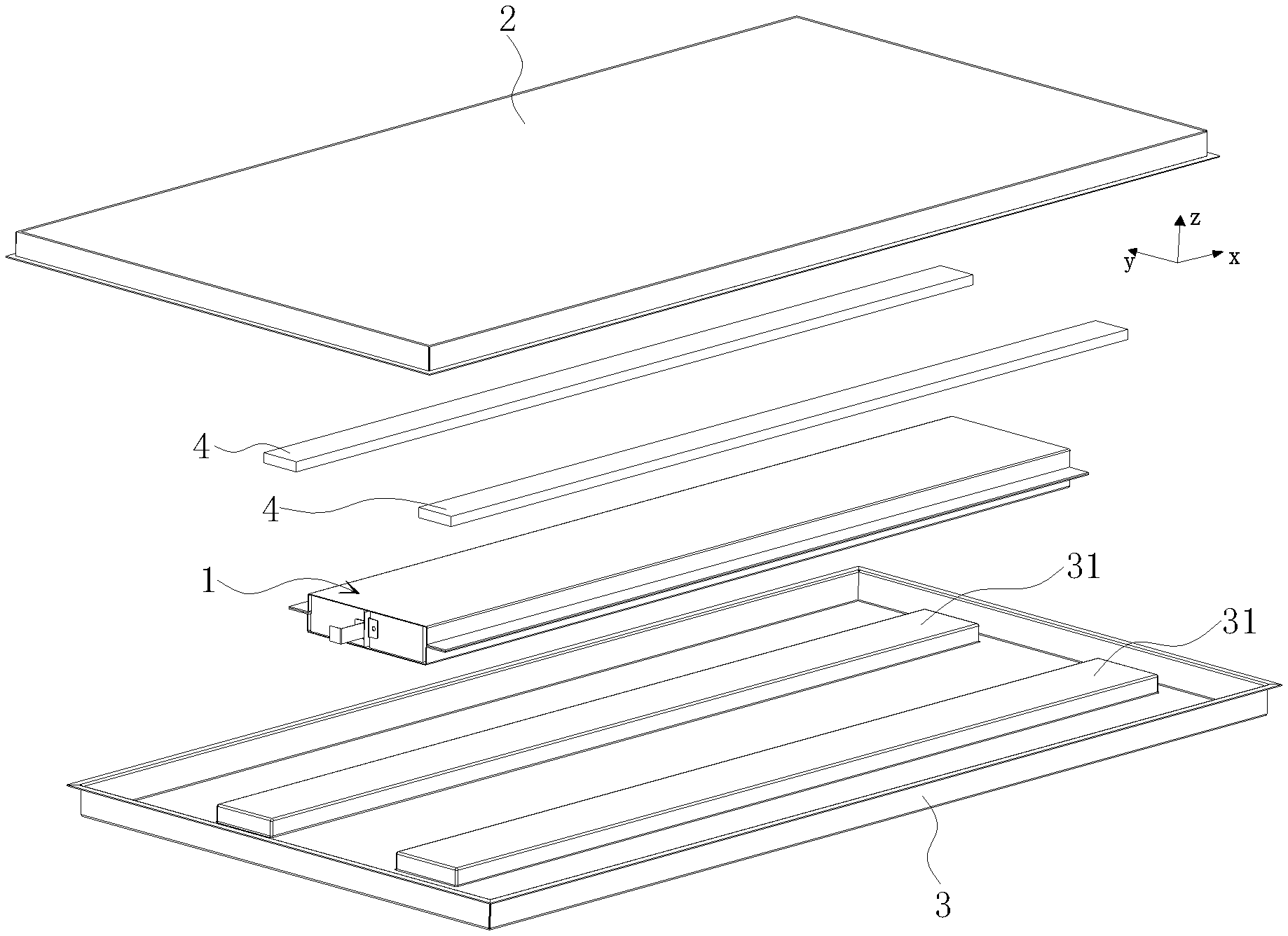
[0020] FIG. 1 is an exploded view of a battery pack according to a specific embodiment;
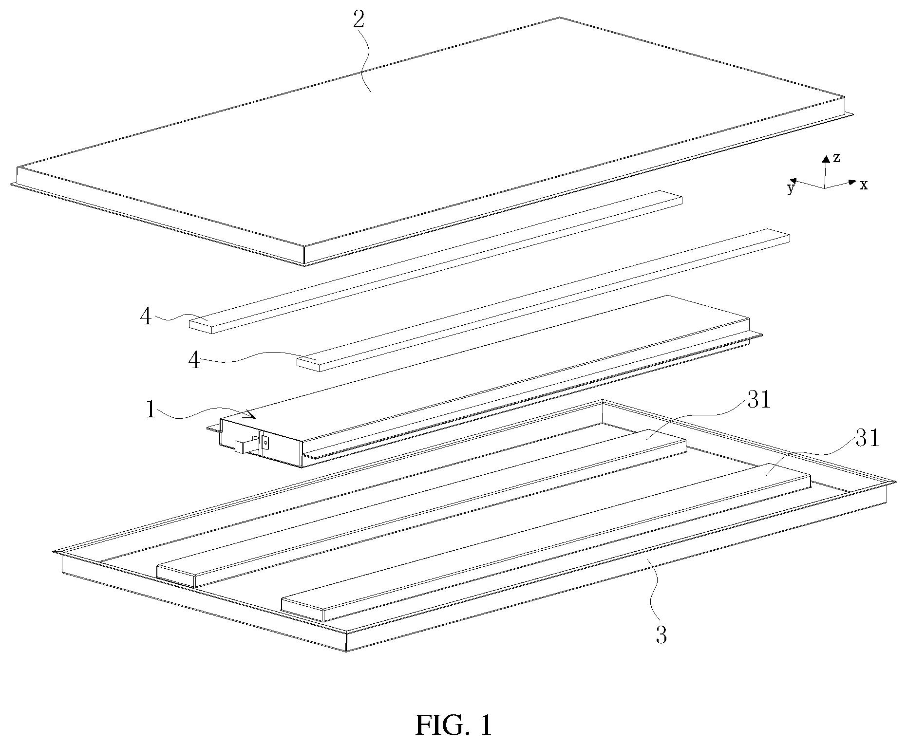
[0021] FIG. 2 is an exploded view of a battery module according to a specific embodiment;
[0022] FIG. 3 is a cross-sectional view of a battery module according to a specific embodiment;
[0023] FIG. 4 is an exploded view of a battery unit array structure according to a specific embodiment;
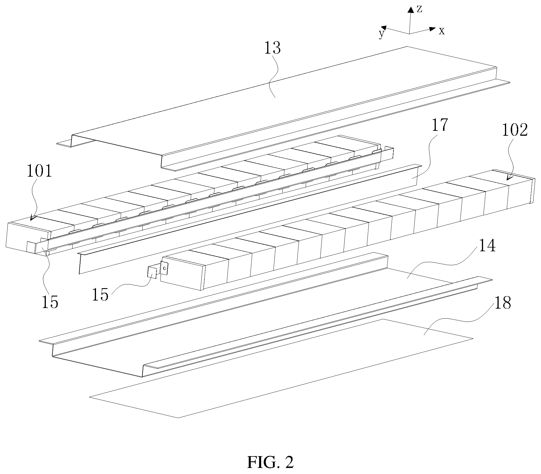
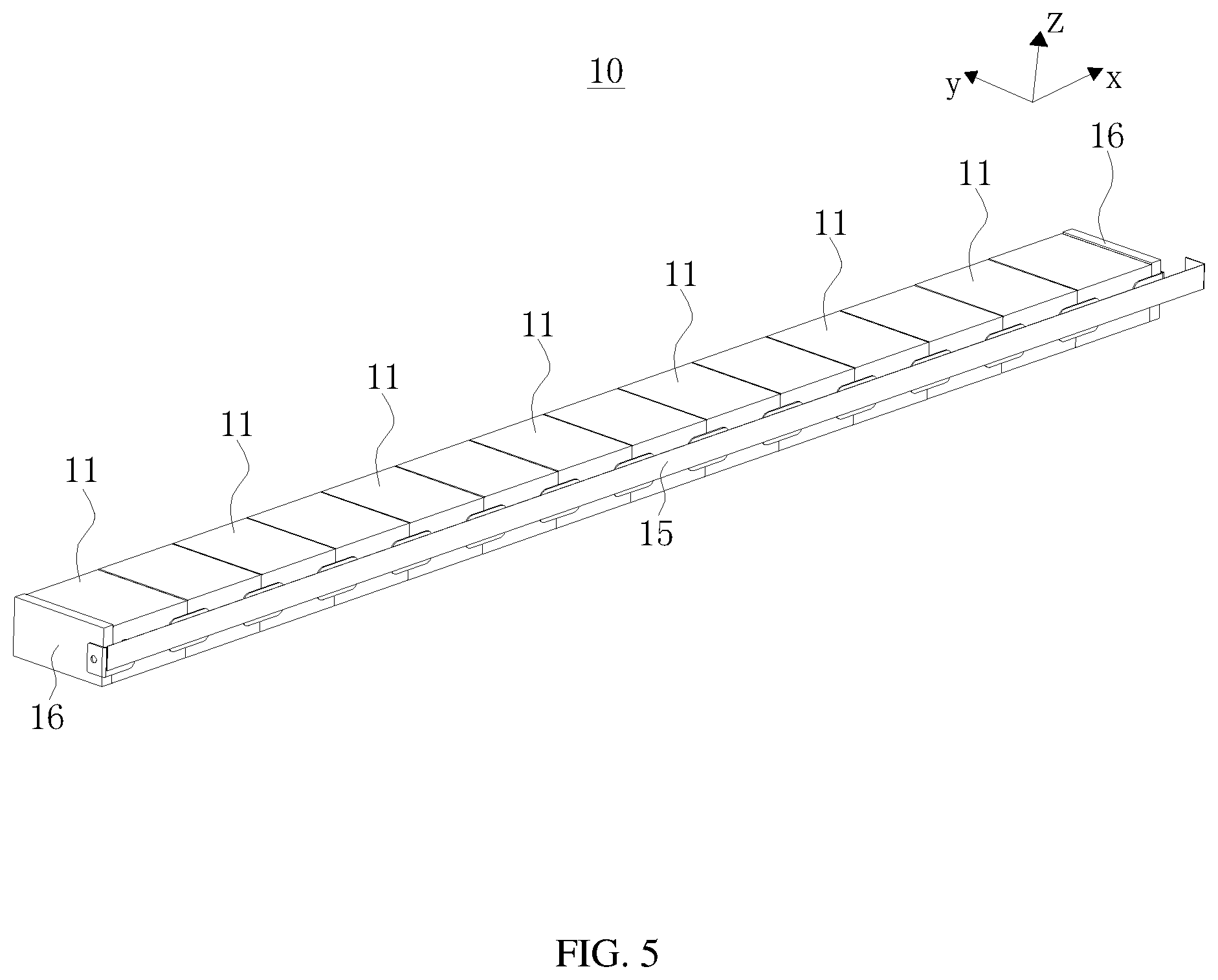
[0024] FIG. 5 is a schematic structural diagram of a battery unit array structure according to a specific embodiment;
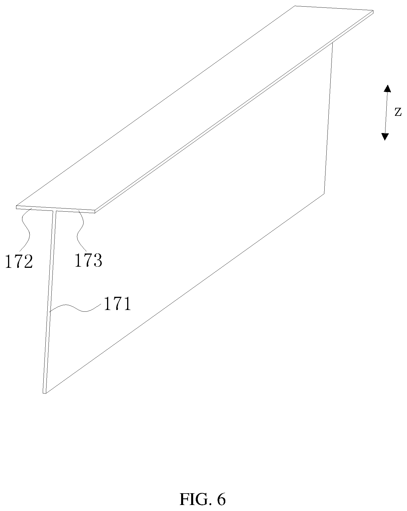
[0025] FIG. 6 is a schematic structural diagram of a fireproof component according to a specific embodiment;
[0026] FIG. 7 is a schematic structural diagram of a fireproof component according to another specific embodiment;
[0027] FIG. 8 is an exploded view of a battery unit according to a specific embodiment;
[0028] FIG. 9 is a cross-sectional view of a battery assembly in form of a wound structure according to a specific embodiment; and
[0029] FIG. 10 is a cross-sectional view of a battery assembly in form of a layered structure according to a specific embodiment.
REFERENCE SINGS
[0030] 1. battery module [0031] 10 battery unit array structure [0032] 101 first battery unit array structure [0033] 102 second battery unit array structure [0034] 11 battery unit [0035] 111 battery assembly [0036] 1111 first electrode plate [0037] 1112 second electrode plate [0038] 1113 separator [0039] 1114 flat surface [0040] 112 battery casing [0041] 1121 first surface [0042] 1122 second surface [0043] 113 electrode terminal connector [0044] 114 cover plate [0045] 115 electrode terminal [0046] 116 vent [0047] 12 busbar [0048] 13 upper cover [0049] 14 lower cover [0050] 15 collecting plate [0051] 16 end plate [0052] 17 fireproof component [0053] 171 fireproof main body [0054] 172 first extension portion [0055] 173 second extension portion [0056] 174 third extension portion [0057] 175 fourth extension portion [0058] 18 fire-extinguishing component [0059] 2 box cover [0060] 3 box body [0061] 31 fixing beam [0062] 4 pressing bar [0063] 5 high-temperature particles.
DESCRIPTION OF EMBODIMENTS
[0064] The technical solutions will be described in detail below with reference to specific embodiments and accompanying drawings in term of technical content, structural features, and objects and effects.
[0065] The terms "first", or "second" in the description are used for a purpose of description only, but not intended to indicate or imply relative importance thereof. Unless otherwise specified or stated, term "a plurality of" means two or more, terms "connected", "fixed", etc. shall be understood in a broad sense. For example, the term "connected" includes various connection manners, such as fixed connection, detachable connection, integrated connection, electrical connection, direct connection or indirect connection via an intermediate medium. These skilled in the art are able to understand specific meanings of the above terms in accordance with specific circumstances.
[0066] It should be understood that terms indicating orientations or positions, such as "upper", "lower", "left", "right", etc., generally are used to describe the orientations or positions with reference to the drawings, and thus should not be construed as a limitation of the present disclosure. It also should be understood that when an element is referred as being "on" or "under" another element, the element can be directly located "on" or "under" another element or connected to another element with an intermediate element.
[0067] FIG. 1 illustrates a battery pack according to an embodiment. The battery pack includes an accommodating box and a plurality of battery modules 1 disposed in the accommodating box. The plurality of battery modules 1 can be arranged either along a horizontal direction (a length direction indicated by arrow x or a width direction indicated by arrow y), or along a vertical direction (a direction indicated by arrow z).
[0068] In an example, the accommodating box includes a box cover 2 and a box body 3. A plurality of fixing beams 31 is provided on the box body 3. In another embodiment, the fixing beams 31 can also be provided on the box cover 2. In the present embodiment, the fixing beams 31 can be protruding beams that protrude upwards from the bottom of the box body 3, or act as separate components that are welded on the bottom of the box body 3.
[0069] The battery pack further includes pressing bars 4. The pressing bars 4 press both ends of the battery module 1 against the fixing beams 31, so as to fix the battery module 1 to the box body 3. In this case, the battery module 1 is fixed by the pressing bars 4.
[0070] In an embodiment as shown in FIG. 2, the battery module 1 includes an upper cover 13, a lower cover 14, a fireproof component 17, a fire-extinguishing component 18, and two battery unit array structures 10 (or more than two battery unit array structures 10). One of the two battery unit array structures 10 is a first battery unit array structure 101, and the other one is a second battery unit array structure 102. Both the first battery unit array structure 101 and the second battery unit array structure 102 are disposed between the upper cover 13 and the lower cover 14.
[0071] In the present embodiment, each of the first battery unit array structure 101 and the second battery unit array structure 102 includes fourteen battery units 11 arranged along the length direction (indicated by arrow x). A number, length, height, volume and the like of the battery units 11 can be adjusted as needed.
[0072] In another embodiment, the battery module 1 includes only one battery unit array structure 10, and each battery unit 11 in the battery unit array structure 10 is provided with a vent 116 facing towards the fireproof component 17.
[0073] The fireproof component 17 is disposed vertically. The vents 116 of the first battery unit array structure 101 and the vents 116 of the second battery unit array structure 102 all face towards the fireproof component 17, and the fireproof component 17 is disposed between the vents 116 of the first battery unit array structure 101 and the vents 116 of the second battery unit array structure 102.
[0074] In this case, as the fireproof component 17 is disposed between the vents 116 of the first battery unit array structure 101 and the vents 116 of the second battery unit array structure 102, the fireproof component 17 separates the battery units 11 of the first battery unit array structure 101 from the battery units 11 of the second battery unit array structure 102, thereby preventing the existing thermal runaway in some battery units from triggering the thermal runaway in adjacent battery units.
[0075] In an example, the fire-extinguishing component 18 is provided below the battery unit array structure 10, and the fire-extinguishing component 18 is provided with a fluid passageway for storing a fire-extinguishing liquid. The fire-extinguishing component 18 extends along a direction in which the battery units 11 are arranged, and has a length in the length direction (indicated by arrow x) that is substantially same as or different from that of the battery unit array structure 10.
[0076] In this embodiment, the fire-extinguishing component 18 is disposed below the lower cover 14, and the fire-extinguishing liquid can be provided inside the fire-extinguishing component 18. In this way, on the one hand, during a normal operating process of the battery module 1, the fire-extinguishing liquid serves as a cooling liquid used for cooling the battery units 11 of the battery unit array structure 10; and on the other hand, when the thermal runaway occurs and the battery unit 11 is on fire, the fire-extinguishing component 18 melts and releases the fire-extinguishing liquid to extinguish the flame, thereby reducing the damage caused by the thermal runaway of the battery unit 11.
[0077] As shown in FIG. 3, when the thermal runaway occurs in the battery unit 11 (the battery unit 11 of the first battery unit array structure 101 or the battery unit 11 of the second battery unit array structure 102), the vent 116 is broken to eject flame and high-temperature particles 5. At this time, the flame and the high-temperature particles 5 are ejected from the battery unit 11 in a horizontal direction (either the length direction indicated by arrow x or the width direction indicated by arrow y), and blocked by the fireproof component 17. Thus, the high-temperature particles 5 fall, and burn through the lower cover 14 as well as the fire-extinguishing component 18, such that the fire-extinguishing liquid in the fire-extinguishing component 18 cool the high-temperature particles 5. In this way, the damage to the battery units 11 caused by the thermal runaway can be reduced.
[0078] In an embodiment shown in FIG. 4 and FIG. 5, the battery unit array structure 10 includes a plurality of battery units 11 and a plurality of busbars 12 electrically connected to the plurality of battery units 11. The plurality of battery units 11 is arranged in the horizontal direction (the length direction indicated by arrow x or the width direction indicated by arrow y). A collecting plate 15 is vertically disposed at a side of the battery unit array structure 10, and the collecting plate 15 is connected to the e battery units 11 in the battery unit array structure 10.
[0079] In the present embodiment, the battery unit array structure 10 further includes two end plates 16, and the two end plates 16 are respectively located at two ends of the plurality of battery units 11 in the horizontal direction (the length direction indicated by arrow x or the width direction indicated by arrow y).
[0080] In a specific embodiment, a side surface of the battery unit 11 is applied with glue and is bonded to an adjacent battery unit 11. The plurality of battery units 11 is provided with the end plates 16 at the two ends, so as to form the battery unit array structure 10. The battery units 11 are electrically connected to one another via the busbars 12. The collecting plate 15 is provided at the positions of busbars 12 of the battery unit array structure 10. The battery unit array structure 10 lies on the lower cover 14, a lower surface of the battery unit array structure 10 is fixed to the lower cover 14 through a structural adhesive, and an upper surface of the battery unit array structure 10 is fixed to the upper cover 13 through a structural adhesive.
[0081] In an embodiment shown in FIG. 6, the fireproof component 17 includes a fireproof main body 171, and a first extension portion 172 connected to an upper end of the fireproof main body 171 and extending towards the first battery unit array structure 101.
[0082] The fireproof component 17 further includes a second extension portion 173 connected to the upper end of the fireproof main body 171 and extending towards the second battery unit array structure 102. In the present embodiment, the first extension portion 172 extends in the direction facing towards the first battery unit array structure 101, and the second extension portion 173 extends in the direction facing towards the second battery unit array structure 102. However, the extension of the first extension portion 172 and the second extension portion 173 are not limited to the extension in the horizontal direction (the length direction indicated by arrow x or the width direction indicated by arrow y) as shown in FIG. 6. It is possible that the first extension portion 172 and the second extension portion 173 extend obliquely upward and downward, or extend along an arc or the like.
[0083] In the present embodiment, for example, the fireproof component 17 is T-shaped. Through the cooperation between the T-shaped fireproof component 17 and the fire-extinguishing component 18, not only the flame and the high-temperature particles 5 can be prevented from being ejected upwards in a vertical direction (a direction indicated by arrow z) and endangering the passenger compartment, but also the flame and high-temperature particles 5 can be ejected downwards to cause melting of the fire-extinguishing component 18, further reducing the damage to the battery units 11 caused by the thermal runaway.
[0084] In an example, the fireproof main body 171, the first extension portion 172 and the second extension portion 173 are formed into one piece. In this way, the processing of the fireproof component 17 can be simplified.
[0085] In another embodiment shown in FIG. 7, the fireproof component 17 includes a fireproof main body 171 and a third extension portion 174 connected to an upper end of the fireproof main body 171, and the third extension portion 174 extends towards the battery unit 11; and/or the fireproof component 17 includes a fireproof main body 171 and a fourth extension portion 175 connected to a lower end of the fireproof main body 17, and the fourth extension portion 175 extends towards the battery unit 11.
[0086] In another embodiment shown in FIG. 7, the fireproof component 17 includes a fireproof main body 171, a third extension portion 174, and a fourth extension portion 175. The positions and shapes of the third extension portion 174 and the fourth extension portion 175 are not specifically limited, as long as the third extension portion 174 is configured to prevent the flame and high-temperature particles 5 from being ejected upwards in the vertical direction (the direction indicated by arrow z) and the fourth extension portion 175 is configured to prevent the flame and high-temperature particles 5 from being ejected downwards in the vertical direction (the direction indicated by arrow z), i.e., both acting as protections. Other embodiment, in which the flame and high-temperature particles 5 can be blocked from burning and damaging the adjacent battery units, shall fall within the protection scope of the present disclosure.
[0087] It should be noted that the above-mentioned fireproof component 17 can include any combination of the first extension portion 172, the second extension portion 173, the third extension portion 174, and the fourth extension portion 175. In practical applications, the shape of the fireproof component 17 can be adjusted according to the actual situation, in order to achieve the optimal effect. The shape of the fireproof component 17 is not limited to the shape shown in the present embodiment.
[0088] The fireproof component 17 has a melting point higher than or equal to 500 .quadrature., such that the flame cannot melt the fireproof component 17, thereby achieving the fireproofness. With respect to the fireproof component 17 made of a mica plate in a specific embodiment, the mica plate has an extremely high melting point (about 1723 .quadrature.), which meets the requirement on the fireproofness of the fireproof component 17, and the mica plate also has excellent processing properties. The fireproof component 17 is not limited to the embodiment of mica plate.
[0089] As shown in FIG. 8, the battery unit 11 includes an electrode assembly 111, a battery casing 112, electrode terminal connectors 113, a cover plate 114, and electrode terminals 115. The battery casing 112 can have a hexahedral shape or any other shape. The battery casing 112 has an inner space for accommodating the electrode assembly 111 and the electrolyte, and an opening. The electrode assembly 111 is accommodated in the battery casing 112, the cover plate 114 covers the opening and configured to enclose the electrode assembly 111 in the battery casing 112, and the electrode assembly 111 is electrically connected to the electrode terminals 115 through the electrode terminal connectors 113. In the present embodiment, there are two electrode terminal connectors 113, i.e., a positive terminal connector 113 and a negative terminal connector 113. The battery casing 112 can be made of a material such as aluminum, aluminum alloy, or plastic.
[0090] The electrode assembly 111 is accommodated in the battery casing 112 and include a first electrode plate 1111, a second electrode plate 1112, and a separator 1113 disposed between the first electrode plate 1111 and the second electrode plate 1112. The first electrode plate 1111 is a positive electrode plate or a negative electrode plate, and the second electrode plate 1112 has opposite polarity to the first electrode plate 1111, i.e., the second electrode plate 1112 is a negative electrode plate or a positive electrode plate. The separator 1113 is an insulator interposed between the first electrode plate 1111 and the second electrode plate 1112. The electrode assembly 111 can be in form of a wound structure (as shown in FIG. 9) or a layered structure (FIG. 10).
[0091] For purpose of illustration, the first electrode plate 1111 is a positive electrode plate and the second electrode plate 1112 is a negative electrode plate. In other embodiments, it is possible that the first electrode plate 1111 is a negative electrode plate and the second electrode plate 1112 is a positive electrode plate. In addition, a positive electrode active material is coated on a coating region of the positive electrode plate, and a negative electrode active material is coated on a coating region of the negative electrode plate. An uncoated region extending from each coating region acts as a tab. The electrode assembly 111 includes two tabs, i.e., a positive tab and a negative tab. The positive tab extends from the coating region of the positive electrode plate, and the negative tab extends from the coating region of the negative electrode plate. The positive electrode tab is electrically connected to the positive electrode terminal 115 through the positive electrode terminal connector 113, and the negative electrode tab is electrically connected to the negative electrode terminal 115 through the negative electrode terminal connector 113.
[0092] The battery casing 112, in an approximately hexahedral form, includes two first surfaces 1121 and two second surfaces 1122. Each of the first surfaces 1121 has a larger area than each of the second surfaces 1122. In the battery module 1, the two second surfaces 1122 of each battery unit 11 are opposite to each other in the horizontal direction (for example, the length direction indicated by arrow x), and the two first surfaces 1121 of each battery unit 11 are opposite to each other in the vertical direction (the direction indicated by arrow z).
[0093] When the electrode assembly 111 is in form of a wound structure, as shown in FIG. 9, the electrode assembly 111 is flat, and the outer surfaces of the electrode assembly 111 include two flat surfaces 1114. The two flat surfaces 1114 are opposite to one another in the vertical direction (the direction indicated by arrow z). In other words, the flat surfaces 1114 are opposite to the first surfaces 1121. The electrode assembly 111 has an approximately hexahedral form, and the flat surface 1114 is substantially parallel to a winding axis and is an outer surface having the largest area. The flat surface 1114 can be a relatively flat surface, rather than a strictly flat surface.
[0094] When the electrode assembly 111 is in form of a layered structure, as shown in FIG. 10, the first electrode plate 1111, the separator 1113, and the second electrode plate 1112 are stacked in the vertical direction (the direction indicated by arrow z), i.e., the first electrode plate 1111 is opposite to the first surface 1121.
[0095] During a charging and discharging process, the electrode assembly 111 inevitably expands in a thickness direction of the first electrode plate 1111. In the electrode assembly 111 of the wound structure, an expansion force is greatest in a direction perpendicular to the flat surface 1114. In the electrode assembly 111 of the layered structure, the expansion force is greatest in a stacking direction of the first electrode plate 1111 and the second electrode plate 1112.
[0096] The electrode assembly 111 can adopt the wound structure or the layered structure. When the electrode assembly 111 is in form of the wound structure, the flat surfaces 1114 are located in the vertical direction (the direction indicated by arrow z). When the electrode assembly 111 is in form of the layered structure, the first electrode plate 1111 and the second electrode plate 1112 are stacked in the vertical direction (the direction indicated by arrow z). It can be seen that, whether the electrode assembly 111 adopts the wound structure or the layered structure, the maximum expansion force applied by the electrode assembly 111 on the battery casing 112 is oriented in the vertical direction.
[0097] On the contrary, in the battery unit 11 of the battery module 1 in the related art, the maximum expansion force applied by the electrode assembly 111 on the battery casing 112 is always oriented in the horizontal direction. The battery module 1 has a much greater size in the horizontal direction than that in the vertical direction. For example, due to the limitation on the height of a vehicle chassis, more battery units 11 have to be stacked in the horizontal direction, the expansion force is accumulated in the horizontal direction. In this regard, the battery module 1 is subjected to an extremely great expansion force in the horizontal direction, and it is necessary to provide very thick end plates on both sides of the battery module 1 in the horizontal direction to resist the expansion force. However, the increased thickness of the end plates can lower the energy density of the battery module 1. In the present embodiment, as the maximum expansion force applied by the electrode assembly 111 on the battery casing 112 is oriented in the vertical direction and the number of battery units 11 stacked in the vertical direction is smaller, the maximum expansion force of the battery module 1 is substantially reduced when compared with the related art.
[0098] The battery unit 11 can produce gas in the battery casing 112 during the charging and discharging process, the produced gas exerts a force on the battery casing 112, thereby intensifying the expansion of the battery casing 112. In the present disclosure, as the first surface 1121 has a larger area than the second surface 1122 and the two first surfaces 1121 of the battery unit 11 are opposite to each other in the vertical direction, the maximum force applied by the produced gas on the battery casing 112 is also oriented in the vertical direction. Compared with the related art, the maximum expansion force of the battery module 1 is further reduced.
[0099] It should be understood that the embodiments according to the present disclosure discussed above are merely illustrative embodiments, but not intended to limit the present disclosure. The technical solution according to the present disclosure can be modified or changed in various manners. Based on the description or the accompanying drawing, any modifications, equivalent replacements, improvements, and direct or indirect applications in other related arts should fall within the scope of protection of the present disclosure.
* * * * *
D00000
D00001
D00002
D00003
D00004
D00005
D00006
D00007
D00008
XML
uspto.report is an independent third-party trademark research tool that is not affiliated, endorsed, or sponsored by the United States Patent and Trademark Office (USPTO) or any other governmental organization. The information provided by uspto.report is based on publicly available data at the time of writing and is intended for informational purposes only.
While we strive to provide accurate and up-to-date information, we do not guarantee the accuracy, completeness, reliability, or suitability of the information displayed on this site. The use of this site is at your own risk. Any reliance you place on such information is therefore strictly at your own risk.
All official trademark data, including owner information, should be verified by visiting the official USPTO website at www.uspto.gov. This site is not intended to replace professional legal advice and should not be used as a substitute for consulting with a legal professional who is knowledgeable about trademark law.