Sorption Heat Exchanger Module
Burk; Roland ; et al.
U.S. patent application number 16/808045 was filed with the patent office on 2020-09-10 for sorption heat exchanger module. The applicant listed for this patent is Mahle International GmbH. Invention is credited to Roland Burk, Barbara Mette.
| Application Number | 20200284487 16/808045 |
| Document ID | / |
| Family ID | 1000004719011 |
| Filed Date | 2020-09-10 |

| United States Patent Application | 20200284487 |
| Kind Code | A1 |
| Burk; Roland ; et al. | September 10, 2020 |
SORPTION HEAT EXCHANGER MODULE
Abstract
A sorption heat exchanger module may include a liquid and gas-tight housing with a sorption zone and with a receiving zone, through which a working fluid may flow. The working fluid may be able to be sorped or desorped in the sorption zone in a sorbent and evaporated or condensed in the receiving zone on a receiver. An outlet path with a displacement space and with an outlet passage leading out of the displacement space may be connected to the receiving zone downstream, so that a gas separated from the working fluid may be able to be collected in the displacement space and via the outlet passage conducted out of the displacement space.
| Inventors: | Burk; Roland; (Stuttgart, DE) ; Mette; Barbara; (Stuttgart, DE) | ||||||||||
| Applicant: |
|
||||||||||
|---|---|---|---|---|---|---|---|---|---|---|---|
| Family ID: | 1000004719011 | ||||||||||
| Appl. No.: | 16/808045 | ||||||||||
| Filed: | March 3, 2020 |
| Current U.S. Class: | 1/1 |
| Current CPC Class: | F25B 43/046 20130101 |
| International Class: | F25B 43/04 20060101 F25B043/04 |
Foreign Application Data
| Date | Code | Application Number |
|---|---|---|
| Mar 4, 2019 | DE | 102019105387.0 |
Claims
1. A sorption heat exchanger module, comprising: a liquid and gas-tight housing with a sorption zone and with a receiving zone, through which a working fluid is flowable; wherein the working fluid is able to be sorped or desorped in the sorption zone in a sorbent and evaporated or condensed in the receiving zone on a receiver; and wherein an outlet path with a displacement space and with an outlet passage leading out of the displacement space is connected to the receiving zone downstream, so that a gas separated from the working fluid is able to be collected in the displacement space and via the outlet passage conducted out of the displacement space.
2. The sorption heat exchanger module according to claim 1, wherein the receiver of the receiving zone is formed through a condensation structure or through a sorption material.
3. The sorption heat exchanger module according to claim 1, wherein a free-standing outer surface of the receiver for the condensing is orientated in a flow passage parallel to a flow direction of the working fluid, so that during the condensing of the working fluid on the receiver, no gas cushion is able to be formed on the outer surface of the receiver.
4. The sorption heat exchanger module according to claim 1, wherein the displacement space is separated from the receiving zone by a convection barrier wall, so that the separated gas in the displacement space is not convectively influenced through the flowing of the working fluid on the convection barrier wall outside the displacement space.
5. The sorption heat exchanger module according to claim 1, wherein at least one of: in the outlet path, a non-return valve is arranged last downstream, so that with a pressure differential on the non-return valve the separated gas is able to be conducted out of the outlet path to the outside and no ambient gas is able to enter the outlet path; and the outlet path is closed off to the outside in a liquid and gas-tight manner by a closure, so that the outlet path is only able to be opened towards the outside as part of the service and the separated gas drained.
6. The sorption heat exchanger module according to claim 1, wherein in the outlet path a temperature sensor is arranged, so that during the draining of the separated gas a temperature change between the through-flowing gas and the through-flowing working fluid is able to be detected and the draining of the separated gas interrupted.
7. The sorption heat exchanger module according to claim 1, wherein the outlet passage out of the displacement space leads directly to the outside and with an orientation of the sorption heat exchanger module suitable for the operation upwards from the displacement space.
8. The sorption heat exchanger module according to claim 1, wherein in the outlet path the displacement space forms a primary gas collection space for storing the separated gas.
9. The sorption heat exchanger module according to claim 1, wherein in the outlet path a secondary gas collection space for storing the separated gas is connected to the outlet passage downstream, wherein with an orientation of the sorption heat exchanger module to suit the operation, the outlet passage fluidically leads at the lowermost point of the secondary gas collection space into the gas collection space.
10. The sorption heat exchanger module according to claim 9, characterized wherein: the outlet passage is a throttling tube, so that the flow rate of the separated gas out of the displacement space into the secondary gas collection space is able to be limited; or in the outlet passage a non-return valve is arranged, so that a return flow of the separated gas out of the secondary gas collection space into the displacement space is able to be limited.
11. The sorption heat exchanger module according to claim 9, wherein in the outlet path an outer passage is provided, which leads out of the secondary gas collection space to the outside, wherein with the orientation of the sorption heat exchanger module suitable for the operation, the outer passage fluidically leads in the uppermost point of the secondary gas collection space into the same and out of the secondary gas collection space upwards.
12. The sorption heat exchanger module according to claim 1, wherein in the outlet path a cooler is provided, so that portions of the working fluid contained in the separated gas are able to be condensed in the outlet path and separated from the separated gas.
13. The sorption heat exchanger module according to claim 1, characterized wherein at least one of: in the outlet path a thermal or catalytic converter is arranged, so that portions of the working fluid contained in the separated gas are able to be chemically converted into decomposition products; and in the outlet path an exchangeable adsorbent cartridge is arranged, so that portions of the working fluid contained in the separated gas are able to be collected.
14. A method for draining a gas admixed to a working fluid in a sorption heat exchanger module according to claim 1, wherein: determining, via a control unit of the sorption heat exchanger module, check values, which are connected to a performance of the sorption heat exchanger module; determining, via the control unit, by way of the determined check values, through at least one of a calculation and a comparison, a performance loss or no performance loss of the sorption heat exchanger module; following the determination of the performance loss, starting, via the control unit, a venting cycle for draining the gas admixed to the working fluid; wherein in the venting cycle in a first part process the working fluid out of the receiver of the receiving zone is evaporated and sorped in the sorbent of the sorption zone; wherein in the venting cycle in a second part process, the working fluid is desorped out of the sorbent of the sorption zone received in the receiving zone by condensing and the admixed gas separated in the outlet path; and wherein in the venting cycle in the second part process, the internal pressure in the sorption heat exchanger module is simultaneously increased and the separated gas drained out of the sorption heat exchanger module via the outlet path.
15. The method according to claim 14, wherein: in the first part process the receiving zone of the sorption heat exchanger module is irregularly supplied with a heat exchanger of a re-cooling circuit; and in the second part process a circulating of a heat exchanger of a re-cooling circuit in the receiving zone is stopped so that the discharge of the condensation heat out of the receiving zone is prevented, thereby bringing the internal pressure in the sorption heat exchanger module above the ambient pressure.
16. The method according to claim 15, wherein the second part process is conducted exactly just as long as a regular sorption or condensation process in the sorption heat exchanger module.
17. The method according to claim 14, wherein: the second part process is stopped as soon as the control unit determines a temperature increase in the outlet path by way of a temperature sensor arranged in the outlet path; or the second part process is stopped in a time-controlled manner.
18. The sorption heat exchanger module according to claim 4, wherein the convection barrier wall is a perforated grid, a perforated plate, a sinter plate or a membrane.
19. The sorption heat exchanger module according to claim 5, wherein the closure is a cap or a plug arranged last downstream in the outlet path.
20. A sorption heat exchanger module, comprising: a liquid and gas-tight housing with a sorption zone and with a receiving zone, through which a working fluid is flowable; wherein the working fluid is able to be sorped or desorped in the sorption zone in a sorbent and evaporated or condensed in the receiving zone on a receiver; and wherein an outlet path with a displacement space and with an outlet passage leading out of the displacement space is connected to the receiving zone downstream, so that a gas separated from the working fluid is able to be collected in the displacement space and via the outlet passage conducted out of the displacement space; wherein one of: in the outlet path the displacement space forms a primary gas collection space for storing the separated gas; or in the outlet path a secondary gas collection space for storing the separated gas is connected to the outlet passage downstream, wherein with an orientation of the sorption heat exchanger module to suit the operation, the outlet passage fluidically leads at the lowermost point of the secondary gas collection space into the gas collection space.
Description
CROSS-REFERENCE TO RELATED APPLICATIONS
[0001] This application claims priority to German Patent Application No. DE 10 2019 105 387.0, filed on Mar. 4, 2019, the contents of which are hereby incorporated by reference in their entirety.
TECHNICAL FIELD
[0002] The invention relates to a sorption heat exchanger module. The invention also relates to a method for training a gas admixed to a working fluid from the sorption heat exchanger module.
BACKGROUND
[0003] Thermally driven sorption heat exchanger modules as refrigeration systems have a high energy savings potential. In particular, cost-effective waste or excess heat can be utilised as drive energy for these and because of this electric networks relieved of load particularly in warm climate zones with a high refrigeration demand in peak load times. In the cold season, the sorption heat exchanger modules can be utilised as heat pumps which by means of burner heat raise additional environmental heat to an adequate temperature level for heating purposes. Particularly interesting are sorption heat exchanger modules which utilise porous solid materials and do not have any moving and thus interference-prone wear parts. For a successful marketing the service requirement over the entire envisaged lifespan of sorption heat exchanger modules both in stationary and also in mobile applications is decisive.
[0004] Disadvantageously, the performance of sorption heat exchanger modules with a low-pressure working fluid of non-condensing gases is negatively affected. In order to keep the partial pressures of these admixed gases as low as possible, a high degree of tightness has to be achieved during the manufacture of the components. Furthermore, during the evacuation and the conditioning of the working fluid and of the desorption of the sorbent major expenditure is required. This has a negative effect on the manufacturing costs. Furthermore it has to be ensured that the materials that are installed within the sorption heat exchanger modules are chemically compatible with the working fluid. Accordingly, the materials must not be chemically attackable by the working fluid and no chemical degradation reactions of the working fluid subject to forming non-condensing gases must occur at the working temperatures.
[0005] However it is extremely difficult in practice to adequately satisfy all described requirements and avoid over the lifespan of sorption heat exchanger modules of 15 to 20 years an accumulation of the non-condensing gases. This is difficult in particular with metastable working fluids such as for example alcohols. In the case of these it can happen that over extended operating periods in hermetically sealed hollow elements of sorption heat exchanger modules, undesirable reformed gases accumulate. These downgrade the kinetic of the substance transfer of the working fluid during cyclical phase changes, in particular during the condensation and during the sorption.
[0006] WO 2007/068481 A1, WO 2010/112433 A2 and WO 2009/103325 A1 describe differently designed sorption heat exchanger modules. In DE 103 10 748 B3, a device and a method for draining a gas admixed to a working fluid in the sorption heat exchanger module is described. Here, the working fluid is completely evaporated in the sorption heat exchanger module and the admixed gases, together with the evaporated working fluid, released. Here, the working fluid together with the admixed gases is disadvantageously drained, which results in an increased loss of the working fluid.
SUMMARY
[0007] The object of the invention therefore is to state an improved or at least alternative embodiment for a sorption heat exchanger module of the generic type, with which the described disadvantages are overcome. In particular, a draining of a gas admixed to a working fluid in the sorption heat exchanger module is to be made possible. Furthermore, the object of the invention is to provide a corresponding method. In particular, it is to be possible to maintain the performance in the sorption heat exchanger module throughout the lifespan with an acceptable service expenditure.
[0008] According to the invention, these objects are solved through the subject of the independent claims. Advantageous embodiments are subject of the dependent claims.
[0009] A generic sorption heat exchanger module comprises a liquid and gas-tight housing with a sorption zone and with a receiving zone, through which a working fluid can flow. Here, the working fluid can be sorped or desorped in the sorption zone in a sorbent and evaporated or condensed in the receiving zone on a receiving means. According to the invention, an outlet path with a displacement space and with an outlet passage leading out of the displacement space is connected to the receiving zone downstream, so that the gas separated from the working fluid can be collected in the displacement space and via the outlet passage conducted out of the same.
[0010] The sorption heat exchanger module can be an adsorption or an absorption module. The working fluid can be for example alcohol--for example methanol or ethanol--or water. The admixed gas can be for example carbon monoxide or carbon dioxide or molecular nitrogen or molecular oxygen. Accordingly, the term "gas-tight" primarily relates to the gases mentioned here. The term "the admixed gas" used here and further on is merely chosen to simplify the description. In the sorption heat exchanger module according to the invention, it can also be a gas mixture of multiple abovementioned and further gases. In the sorption heat exchanger module according to the invention, the admixed gas is separated from the working fluid in the receiving zone and collected in the displacement space. Because of this, the receiving zone forms a substance sink for the working fluid. Because of this, the working fluid is extracted from the circuit of the working fluid and no longer affects the performance of the sorption heat exchanger module negatively. The volume of the displacement space can be configured in such a manner that the complete quantity of the admixed gas can be received in the same. Because of this, the sorption heat exchanger module can be kept largely free of the admixed gas for a defined operating period. Because of this, the displacement space forms an intermediate storage unit for the gas separated from the working fluid, until the same is conducted out of the displacement space to the outside. Advantageously, the receiving means of the receiving zone can be formed through a condensation structure or through a sorption material. By way of the outlet passage, the already separated gas can be conducted out of the displacement space and out of the sorption heat exchanger module to the outside if required. The term "conducted to the outside" in this connection does not mean that the potentially environmentally-harmful separated gas is liberated from the sorption heat exchanger module into the surroundings. In particular, the possibly environmentally-harmful gas can be collected during the conducting out of the sorption heat exchanger module and disposed of in an environmentally appropriate manner.
[0011] Advantageously it can be provided that an outer surface of the receiving means standing free for the condensing is orientated in a flow passage parallel to the flow direction of the working fluid. During the condensing of the working fluid on the receiving means, no gas cushion can be formed on the outer surface of the receiving means because of this. In other words, the admixed gas cannot settle on the outer surface of the receiving means. Through the parallel or tangential flow direction of the working fluids on the receiving zone, the admixed gas is taken away from the outer surface of the receiving means so that the working fluid can be condensed unhindered in the receiving zone. Because of this, the concentration of the admixed gas along the receiving zone in the flow direction of the working fluid increases continuously so that the admixed gas can enter the displacement space connected downstream almost free of working fluid.
[0012] In order to keep the already separated gas in the displacement space, the displacement space can be separated from the receiving zone through a convection barrier wall. In this way the gas separated in the displacement space cannot be convectively influenced by the flowing of the working fluid on the convection barrier wall outside the displacement space. In other words, the separated gas cannot be dragged along out of the displacement space and not be diluted in the displacement space. Preferably, the convection barrier wall is a perforated grid, a perforated plate, a sinter plate or a membrane. Then, the convection barrier wall comprises multiple openings which are so small that exclusively a slow and laminar transport of the admixed gas through the convection barrier wall is possible. The term "slow" in this connection means that a laminar compression of the separated gas in the displacement space is possible but a convective escape of the separated gas out of the displacement space is prevented. The receiving zone forms a substance sink for the working fluid and the admixed gas is concentrated in the flow direction along the receiving zone and enters the displacement space through the convection barrier wall. During the subsequent evaporation of the working fluid out of the receiving means, the collected gas cannot escape from the displacement space. Because of this, the concentration of the admixed gas in the displacement space during many alternating condensation and evaporation cycles can increase through the periodic pressure changes.
[0013] In a further development of the sorption heat exchanger module it is provided that in the outlet path a non-return valve is arranged last downstream. With a pressure differential on the non-return valve, the separated gas can be discharged from the outlet path and an ambient gas cannot enter the outlet path. Practically, the non-return valve opens only when the pressure within the sorption heat exchanger module exceeds the pressure in the surroundings by a predetermined value. Alternatively or additionally it can be provided that the outlet path is kept liquid and gas-tight towards the outside by way of a closure unit arranged last downstream in the discharge path. The closure unit can preferentially be a closure cap or a closure plug. With this solution, the outlet path can only be opened as part of the service and the separated gas drained. Advantageously, for the liquid and gas-tight closing, highly vacuum-tight or firmly bonded closure techniques--for example metal seals or sealing varnishes--can be employed. The term "arranged last downstream" in this connection means that regardless of the number and the configuration of further components of the outlet path, the non-return valve and/or the closure unit are flowed through last during the draining of the admixed gas. When in the outlet path both the non-return valve and also the closure unit are provided, the closure unit is arranged downstream of the non-return valve.
[0014] The outlet passage can lead out of the displacement space directly to the outside and with the orientation of the sorption heat exchanger module suitable for the operation, from the displacement space upwards. The outlet passage orientated upwards causes, in a non-return valve fixed to the same, that the condensed working fluid that has escaped to the outside with the separated gas is present at the non-return valve and upon an unintentional minor leakage of the non-return valve only the pure working fluid that is largely free of ambient gases can flow back into the displacement space. The term "upwards" in this connection refers to the effect of the earth gravity which is directed from the "top" to the "the bottom".
[0015] Advantageously it can be provided that in the outlet path a temperature sensor is arranged. When draining the separated gas, a temperature change between the through-flowing gas and the through-flowing working fluid can thus be determined and the draining of the separated gas can be timely interrupted. Surprisingly it has been shown that the temperature sensor reacts hardly noticeably to an escaping of the admixed non-condensing gas. By contrast, the temperature sensor shows a steep temperature increase as soon as the escaping gas contains high vapour portions of the working fluid. This can be explained in that the vapour of the working fluid condenses on the temperature sensor and heats the same by liberating the condensation heat. Because of this, the determined temperature increase on the temperature sensor is highly suitable for detecting the optimum end of the draining and thereby minimise the loss of the working fluid.
[0016] In an advantageous configuration of the sorption heat exchanger module it is provided that in the outlet path the displacement space forms a primary gas collection space for storing the separated gas. The primary gas collection space is then designed as an enlargement of the displacement space. By way of the pressure change in the receiving zone, the admixed gas can be exchanged between the receiving zone and the displacement space, so that the separated gas is concentrated in the displacement space. In the process, the function of the sorption heat exchanger module is not negatively affected. Alternatively to this it can be provided that in the outlet path a secondary gas collection space for storing the separated gas is connected to the outlet passage downstream. Here, the outlet passage during the orientation of the sorption heat exchanger module to suit the operation fluidically opens in the lowermost point of the gas collection space. Then, the outlet passage directly connects the displacement space with the gas collection space. The term "bottom" in this connection refers to the effect of the earth gravity which is directed from "top" to "bottom".
[0017] With the secondary gas collection space it can be additionally provided that the outlet passage is a throttling tube, so that the flow rate of the separated gas out of the displacement space into the secondary gas collection space can be limited. Furthermore, convective return flow of the working fluid into the displacement space and further into the receiving zone can also be reduced by way of this. Preferentially, the cross section and the length of the throttling tube are selected so that the working fluid condensed in the secondary gas collection space can be returned with a corresponding pressure gradient. Alternatively, a non-return valve can be arranged in the outlet passage so that a return flow of the separated gas from the secondary gas collection space into the displacement space can be prevented. Because of this, the secondary gas collection space forms a pressure storage unit. In this advantageous embodiment of the secondary gas collection space, the separated gas can be transferred step-by-step from the displacement space into the secondary collection space, as a result of which the pressure in the secondary collection space is then correspondingly increased step-by-step. The working fluid admixed to the separated gas can condense in the secondary gas collection space and returned into the receiving zone. This can be realised for example through a provided minimum leakage of the non-return valve in the outlet passage. The secondary collection space can be subjected to extraction or disposal within the scope of a service process.
[0018] With the secondary gas collection space, an outer passage can be practically provided in the outlet path which leads out of the secondary gas collection space to the outside. With the orientation of the sorption heat exchanger module suitable for the operation, the outer passage fluidically opens on the uppermost point of the secondary gas collection space into the same. The outer passage furthermore leads out of the secondary gas collection space upwards. The last downstream non-return valve and/or the last downstream closure unit are then practically arranged in the outer passage.
[0019] In addition it can be provided that in the outlet path a thermal or catalytic conversation device is arranged. The conversion device can then chemically convert the separated gas and/or portions of the working fluid contained in the separated gas into harmless decomposition products. By way of this, neither the environmentally harmful separated gas and/or portions of the environmentally harmful working fluid contained in the separated gas can then be decomposed and liberated into the environment. The conversion device can comprise various known technical solution components. For example, the separated gas and/or portions or the working fluid contained in the separating gas can be fed to an already existing combustion device, a fuel heater or a combustion engine. Alternatively, the separated gas and/or portions of the working fluid contained in the separated gas can be fed to an optionally heated decomposition catalytic converter. The decomposition catalytic converter can be for example an existing oxidation catalytic converter of an internal combustion engine. Alternatively or additionally it can be provided that in the outlet path an exchangeable adsorbent can be arranged. Portions of the working fluid contained in the separated gas can then be collected in the adsorbent cartridge and retained. The adsorbent cartridge can then be designed for example as a replacement cartridge which can be replaced if required as part of the service. Because of the fact that the adsorbent cartridge retains the working fluid, the same cannot enter the environment during the draining of the separated gas.
[0020] The invention also relates to a method for draining a gas admixed to a working fluid from the sorption heat exchanger module described above. There, a control unit of the sorption heat exchanger module determines check values which are connected to the performance of the sorption heat exchanger module. The check values can be determined for example through temperature sensors installed in the sorption heat exchanger module. Following this, the control unit determines by way of the determined check values a performance loss or no performance loss of the sorption heat exchanger module by calculation or by a comparison. Thus, the control unit can for example offset the determined check values against one another and subsequently compare the check values offset against one another with expectation values. For example minimum temperature differentials to be achieved through a fluid inlet and a fluid outlet of the sorption heat exchanger module as a function of the re-cooling and evaporation temperature can serve as expectation values for example. If the check values offset against one another do not correspond to the expectation values, the control unit determines a performance loss in the sorption heat exchanger module.
[0021] Following the determination of the performance loss, the control unit starts in the sorption heat exchanger module a venting cycle for draining the gas admixed to the working fluid. In the venting cycle, the working fluid in a first part process is evaporated out of the receiving means of the receiving zone and sorped in the sorbent of the sorption zone. Then, the working fluid, in a second part process of the venting cycle, is desorbed out of the sorbent of the sorption zone, received in a receiving zone of the sorption heat exchanger module through condensing; and the admixed gas separated in the outlet path. In the second part process of the venting cycle, the internal pressure in the sorption heat exchanger module is additionally increased at the same time and the separated gas drained out of the sorption heat exchanger module via the outlet path. It can be provided that the second part process is conducted exactly as long as a regular sorption or condensation process in the sorption heat exchanger module. Because of this, the influence of the venting cycle in the sorption heat exchanger module on neighbouring sorption heat exchanger modules can be minimised.
[0022] In the first part process, the working fluid is evaporated in the receiving zone and sorped in the sorbent, for the purpose of which the receiving zone of the sorption heat exchanger module is irregularly supplied with a heat exchanger fluid of a re-cooling circuit. Through the first part process, a large quantity of the working fluid can be sorped in the sorbent of the sorption zone so that in the second part process an adequate quantity of the working fluid can be desorbed in the sorption zone and condensed in the receiving zone. Because of this, the condensation heat can be increased, which is liberated in the receiving zone in the second part process.
[0023] In the second part process, the working fluid now condenses in the receiving zone and the admixed gas is separated from the working fluid. There, the working fluid can be conducted parallel in a flow passage on a free-standing outer surface of the receiving means for condensing. Through the parallel or tangential conducting of the working fluid on the receiving zone, the concentration of the admixed gas along the receiving zone continuously increases in the flow direction of the working fluid so that the admixed gas can enter into the displacement space connected downstream almost free of working fluid.
[0024] In the second part process, the internal pressure in the sorption heat exchanger module is increased at the same time. For this purpose, a circulating of a heat exchanger fluid of a re-cooling circuit in the receiving zone can be stopped so that the discharge of the condensation heat out of the receiving zone is prevented. Because of this, the temperature in the receiving zone and the internal pressure in the sorption heat exchanger module increase. The temperatures range between 60.degree. C. and 125.degree. C. depending on the working fluid and the internal pressure in the sorption heat exchanger module is between 1 bar and 2 bar. The separated gas is now discharged from the sorption heat exchanger module, for the purpose of which for example a non-return valve is opened by way of the generated pressure differential and the separated gas discharged for example into a secondary gas convection space.
[0025] Advantageously, the second part process can be stopped as soon as the control unit determines a temperature change in the outlet path through a temperature sensor arranged in the same. Alternatively, the second part process can be stopped in a time-controlled manner. As already explained above, the loss of the working fluid in the sorption heat exchanger module can thereby be advantageously reduced. For stopping the second part process, the circulating of a heat exchanger fluid of a re-cooling circuit in the receiving zone is restarted and the condensation heat is now discharged. Because of this, the temperature in the receiving zone and the internal pressure in the sorption heat exchanger module drop. The opened non-return valve is closed and the separated gas remains for example in the secondary gas collection space.
[0026] Further important features and advantages of the invention are obtained from the subclaims, from the drawings and from the associated figure description by way of the drawings.
[0027] It is to be understood that the features mentioned above and still to be explained in the following cannot only be used in the respective combination stated but also in other combinations or by themselves without leaving the scope of the present invention.
[0028] Preferred exemplary embodiments of the invention are shown in the drawings and are explained in more detail in the following description, wherein same reference numbers relate to same or similar or functionally same components.
BRIEF DESCRIPTION OF THE DRAWINGS
[0029] It shows, in each case schematically
[0030] FIG. 1 is a part view of a sorption heat exchanger module according to the invention in a first embodiment;
[0031] FIG. 2 is a part view of the sorption heat exchanger module according to the invention in a second embodiment;
[0032] FIG. 3 is a part view of the sorption heat exchanger module according to the invention in a third embodiment.
DETAILED DESCRIPTION
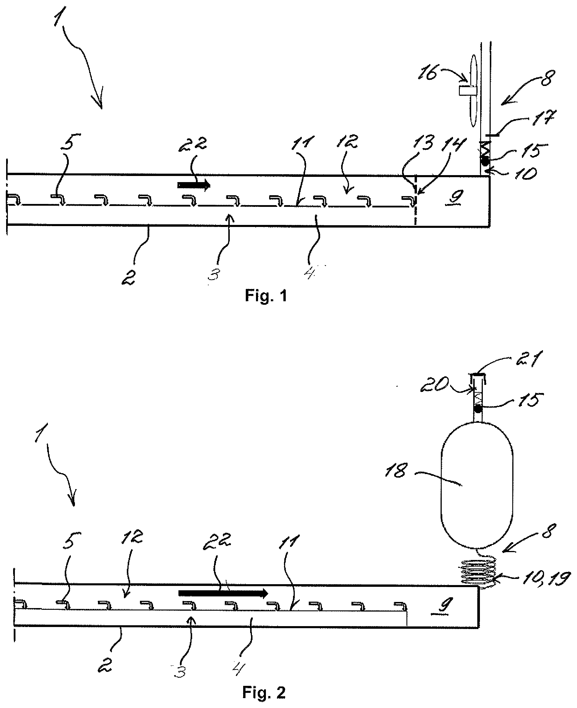
[0033] FIG. 1 shows a part view of a sorption heat exchanger module 1 according to the invention in a first embodiment. The sorption heat exchanger module 1 comprises a liquid and gas-tight housing 2 having a receiving zone 3 having a receiving means 4 and having a sorption zone--not shown here. The sorption zone and the receiving zone 3 can be flowed through by a working fluid 5. The working fluid 5 can be sorped or desorped in the sorption zone and evaporated or condensed in the receiving zone 3 on the receiving means 4. In the sorption heat exchanger module 1 according to the invention, an outlet path 8 with a displacement space 9 and with an outlet passage 10 leading out of the displacement space 9 is connected to the receiving zone 3 downstream. In the first embodiment of the sorption heat exchanger module 1, the outlet passage 10 leads directly to the outside. A free-standing outer surface 11 of the receiving means 4 for the condensing or evaporating is orientated in a flow passage 12 parallel to the flow direction 22 of the working fluid 5.
[0034] During the condensing of the working fluid 5 in the receiving means 4, the working fluid 5 flows past the outer surface 11 parallel or tangentially. Because of this, the gas admixed to the working fluid 5 cannot settle on the outer surface 11 of the receiving means 4. Because of this, the working fluid during the condensing can be received unhindered in the receiving means 4 and retained as indicated by arrows. Consequently, the receiving zone 3 forms a substance sink for the working fluid 5. In the process, a separating of the admixed gas from the working fluid 5 occurs on the receiving means 4, which is then removed from the outer surface 11 of the receiving means 4 in the flow direction 22 of the working fluid 5. Through the condensing of the working fluid 5, the admixed gas is concentrated along the receiving zone 3 in the flow direction 22 of the working fluid 5 and enters the displacement space 9 downstream of the receiving zone 3 almost free of working fluid. Because of this, the admixed gas is extracted from the circuit of the working fluid 5 and no longer negatively affects the performance of the sorption heat exchanger module 1.
[0035] In order to hold the already separated gas in the displacement space 9, the same is separated from the receiving zone 3 and from the flow passage 12 by a convection barrier wall 13. The convection barrier wall 13 can be a perforated grid, a perforated plate, a sinter plate or a membrane and comprises multiple openings 14. The openings 14 are so small that exclusively a slow and laminar transport of the admixed gas through the convection barrier wall 13 is possible. Because of this, the already separated gas in the displacement space 9 is not convectively influenced by the working fluid 5 flowing into the flow passage 12 and remains securely retained in the displacement space 9 over multiple phase changes of the working fluid 5. Here, the displacement space 9 consequently forms a primary gas collection space. Here, the volume of the displacement space 9 is designed in such a manner that the complete quantity of the admixed gas can be received in the same.
[0036] By way of the outlet passage 10, the already separated gas can be conducted out of the displacement space 9 to the outside when required. In order to reduce the loss of the working fluid 5 during the draining out of the sorption heat exchanger module 1, a non-return valve 15 is arranged last downstream in the outlet passage 10. At a pressure differential in the outlet path 8 the non-return valve 15 opens and the admixed gas can be conducted out of the displacement space 9. Furthermore, a cooling device 16--here a blower--is arranged in the outlet passage 10. Through the cooling device 16, portions of the working fluid 5 contained in the separated gas can be condensed in the outlet passage 10 and separated from the separated gas. Following this, the same can be returned into the flow passage 12. A temperature sensor 17, furthermore, monitors the temperature change in the outlet path 8 during the draining of the admixed gas. At a temperature increase, which correlates to a high vapour portion of the working fluid 5, the outlet path 8 can be closed. Because of this, the loss of the working fluid 5 can be reduced. Draining the admixed gas can take place as part of the service during which the outlet path 8 is opened to the outside. When the separated gas is not environmentally harmful, the same can be conducted to the outside if required even outside the service.
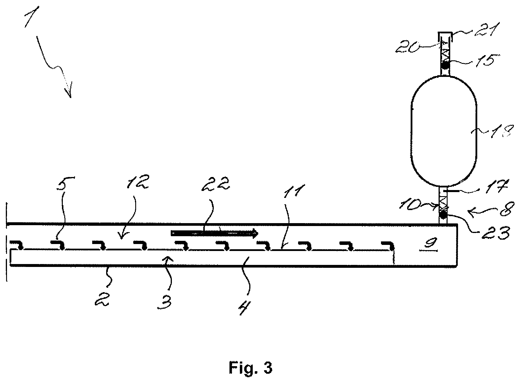
[0037] FIG. 2 shows a part view of the sorption heat exchanger module 1 according to the invention in a second embodiment. Here, a secondary gas collection space 18 for storing the separated gas is connected to the outlet passage 10 downstream. Here, the outlet passage 10 fluidically opens at the lowermost point of the secondary gas collection space 18 into the same. Here, the outlet passage 10 is a throttling tube 19 which limits the flow rate of the separated gas out of the displacement space 9 into the secondary gas collection space 18. The gas collected in the secondary gas collection space 18 can be conducted to the outside as part of the service via an outer passage 20, which at an uppermost point of the gas collection space 18 fluidically opens into the same and leads to the outside. In the outer passage 20, the non-return valve 15 is arranged and the outer passage 20 is closed in a liquid and gas-tight manner through a closure unit 21 arranged downstream after the non-return valve 15. As part of the service, the closure unit 21 can then be opened and the gas stored in the secondary gas collection space 18 conducted out of the sorption heat exchanger module to the outside. In principle, the non-return valve 15 is not necessarily required with the second embodiment of the sorption heat exchanger module 1.
[0038] FIG. 3 now shows a part view of the sorption heat exchanger module 1 according to the invention in a third embodiment. Here, the secondary gas collection space 18 is designed in the form of a pressure storage unit. In the outlet passage 10, a further non-return valve 23 is arranged for this purpose, which separates the displacement space 9 from the secondary gas collection space 18. Otherwise, the sorption heat exchanger module 1 here corresponds to the sorption heat exchanger module 1 in the second embodiment.
[0039] It is to be understood that the first embodiment, the second embodiment and the third embodiment of the sorption heat exchanger module 1 are only exemplary and that further forms of the sorption heat exchanger module 1 are also conceivable. Both in FIG. 1 and also in FIG. 2 and FIG. 3 the sorption heat exchanger module 1 is located in an orientation to suit the operation.
* * * * *
D00000
D00001
D00002
XML
uspto.report is an independent third-party trademark research tool that is not affiliated, endorsed, or sponsored by the United States Patent and Trademark Office (USPTO) or any other governmental organization. The information provided by uspto.report is based on publicly available data at the time of writing and is intended for informational purposes only.
While we strive to provide accurate and up-to-date information, we do not guarantee the accuracy, completeness, reliability, or suitability of the information displayed on this site. The use of this site is at your own risk. Any reliance you place on such information is therefore strictly at your own risk.
All official trademark data, including owner information, should be verified by visiting the official USPTO website at www.uspto.gov. This site is not intended to replace professional legal advice and should not be used as a substitute for consulting with a legal professional who is knowledgeable about trademark law.