Oil Baffle For Gas Turbine Fan Drive Gear System
Sheridan; William G. ; et al.
U.S. patent application number 16/833754 was filed with the patent office on 2020-09-10 for oil baffle for gas turbine fan drive gear system. The applicant listed for this patent is United Technologies Corporation. Invention is credited to Michael E. McCune, William G. Sheridan.
| Application Number | 20200284336 16/833754 |
| Document ID | / |
| Family ID | 1000004845379 |
| Filed Date | 2020-09-10 |

| United States Patent Application | 20200284336 |
| Kind Code | A1 |
| Sheridan; William G. ; et al. | September 10, 2020 |
OIL BAFFLE FOR GAS TURBINE FAN DRIVE GEAR SYSTEM
Abstract
A method of assembling an epicyclic gear train includes providing a unitary carrier that includes spaced apart walls and circumferentially spaced mounts interconnecting the walls, spaced apart apertures provided between the mounts at an outer circumference of the carrier, gear pockets provided between the walls and mounts extending to the apertures, and a central opening in at least one of the walls, inserting an intermediate gear through the central opening and moving the intermediate gear radially into the gear pocket to extend through the aperture, inserting a baffle into the carrier, and inserting a sun gear through the central opening to intermesh with the intermediate gear.
| Inventors: | Sheridan; William G.; (Southington, CT) ; McCune; Michael E.; (Colchester, CT) | ||||||||||
| Applicant: |
|
||||||||||
|---|---|---|---|---|---|---|---|---|---|---|---|
| Family ID: | 1000004845379 | ||||||||||
| Appl. No.: | 16/833754 | ||||||||||
| Filed: | March 30, 2020 |
Related U.S. Patent Documents
| Application Number | Filing Date | Patent Number | ||
|---|---|---|---|---|
| 15808613 | Nov 9, 2017 | 10605351 | ||
| 16833754 | ||||
| 14485039 | Sep 12, 2014 | 9874274 | ||
| 15808613 | ||||
| 13861602 | Apr 12, 2013 | 8898900 | ||
| 14485039 | ||||
| 13346790 | Jan 10, 2012 | 8640336 | ||
| 13861602 | ||||
| 12718436 | Mar 5, 2010 | 8276275 | ||
| 13346790 | ||||
| 11481112 | Jul 5, 2006 | 7704178 | ||
| 12718436 | ||||
| Current U.S. Class: | 1/1 |
| Current CPC Class: | F16H 57/0486 20130101; Y10T 29/49316 20150115; F16H 57/082 20130101; F02C 7/36 20130101; F05D 2260/98 20130101; F16H 57/0482 20130101; F16H 57/0427 20130101; Y10T 29/4932 20150115; F16H 57/0423 20130101; F16H 57/0421 20130101; F01D 25/18 20130101; F05D 2230/60 20130101; F02C 3/04 20130101; Y10T 29/49464 20150115; F16H 57/0479 20130101; F05D 2260/40311 20130101; Y10T 29/49323 20150115; F16H 57/046 20130101 |
| International Class: | F16H 57/04 20060101 F16H057/04; F01D 25/18 20060101 F01D025/18; F02C 7/36 20060101 F02C007/36; F02C 3/04 20060101 F02C003/04 |
Claims
1. A method of assembling an epicyclic gear train comprising the steps of: a) providing a unitary carrier that includes spaced apart walls and circumferentially spaced mounts interconnecting the walls, spaced apart apertures provided between the mounts at an outer circumference of the carrier, gear pockets provided between the walls and mounts extending to the apertures, and a central opening in at least one of the walls; b) inserting an intermediate gear through the central opening and moving the intermediate gear radially into the gear pocket to extend through the aperture; c) inserting a baffle into the carrier; and d) inserting a sun gear through the central opening to intermesh with the intermediate gear.
2. The method according to claim 1, wherein step c) includes securing the baffle to the carrier near the intermediate gear.
3. The method according to claim 2, wherein step c) includes bolting the baffle to one of the walls.
4. The method according to claim 1, comprising inserting a tube through a hole in the carrier to communicate with a lubrication passage in the baffle.
5. The method according to claim 1, comprising securing a torque frame to the mounts, the torque frame fixed relative to a housing.
Description
REFERENCE TO RELATED APPLICATIONS
[0001] This application is a continuation of U.S. patent application Ser. No. 15/808,613, filed on 9 Nov. 2017, which is a continuation of U.S. patent application Ser. No. 14/485,039, filed on 12 Sep. 2014, which is a continuation of U.S. patent application Ser. No. 13/861,602, filed on 12 Apr. 2013, now U.S. Pat. No. 8,898,900, issued Feb. 2, 2014, which is a continuation of U.S. patent application Ser. No. 13/346,790, filed on 10 Jan. 2012, now U.S. Pat. No. 8,640,336, issued 4 Feb. 2014. U.S. patent application Ser. No. 13/346,790 is a continuation of U.S. patent application Ser. No. 12/718,436, filed on 5 Mar. 2010, now U.S. Pat. No. 8,276,275, issued 2 Oct. 2012 which is a divisional of U.S. patent application Ser. No. 11/481,112, filed 5 Jul. 2006, now U.S. Pat. No. 7,704,178, issued 27 Apr. 2010.
BACKGROUND OF THE INVENTION
[0002] This disclosure relates to a gas turbine engine architecture.
[0003] Gas turbine engines typically employ an epicyclic gear train connected to a turbine section of the engine, which is used to drive the turbo fan. In a typical epicyclic gear train, a sun gear receives rotational input from a turbine shaft through a compressor shaft. A carrier supports intermediate gears that surround and mesh with the sun gear. A ring gear surrounds and meshes with the intermediate gears. In arrangements in which the carrier is fixed against rotation, the intermediate gears are referred to as "star" gears and the ring gear is coupled to an output shaft that supports the turbo fan. In arrangements in which the ring gear is fixed against rotation, the intermediate gears are referred to as "planetary" gears and the carrier is coupled to the output shaft that supports the turbo fan.
[0004] The epicyclic gear train gears must receive adequate lubrication during operation of the turbine engine. To this end, the carrier includes oil spray bars arranged between the intermediate gears and the sun gear to spray oil directly on those gears. Separate oil baffles, which may be integral with or separate from the carrier, are arranged between the intermediate gears to collect the sprayed oil and retain it in the area of the intermediate gears for prolonged lubrication before the oil is collected in a lubricant gutter associated with the ring gear.
[0005] Prior art carrier arrangements have required multiple components and complicated assembly in order to accommodate the oil baffles. For example, one or both of the side walls of the carrier must be assembled around the intermediate gears resulting in a multi-piece carrier. Furthermore, separate oil spray bars and oil baffles complicate assembly and increase cost. What is needed is a simplified oil baffle and spray bar arrangement that enables a simpler and less expensive carrier design.
SUMMARY OF THE INVENTION
[0006] In one exemplary embodiment, a turbo fan engine includes a housing that supports a compressor section. At least one compressor hub is within the compressor section. A compressor shaft is arranged in the compressor section. An epicyclic gear train is coupled to the compressor shaft. At least one compressor hub and the compressor shaft are coupled at a common attachment point. The epicyclic gear train includes a carrier. A sun gear and intermediate gears are arranged about and intermeshing with the sun gear. The intermediate gears are supported by the carrier. A baffle is supported relative to the carrier and includes a lubrication passage near at least one of the sun gear and intermediate gears for directing a lubricant on at least one of the sun gear and the intermediate gears.
[0007] In a further embodiment of any of the above, the lubrication passage includes a primary passage that extends laterally between the walls and first and second passages and is in communication with the primary passage and respectively terminates near the sun gear and intermediate gears.
[0008] In a further embodiment of any of the above, a ring gear intermeshes with the intermediate gears and an output shaft is interconnected to the ring gear. An input shaft is interconnected to the sun gear.
[0009] In a further embodiment of any of the above, the carrier is fixed relative to a housing.
[0010] In a further embodiment of any of the above, the carrier includes mounts. The housing supports a torque frame that is secured to the mounts.
[0011] In a further embodiment of any of the above, the baffle is secured to the carrier with fasteners.
[0012] In a further embodiment of any of the above, the baffle is integral with the carrier.
[0013] In another exemplary embodiment, a turbo fan engine includes at least one compressor hub within a compressor section. A compressor shaft is arranged in the compressor section. An epicyclic gear train is coupled to the compressor shaft. At least one compressor hub and the compressor shaft are coupled at a common attachment point. The epicyclic gear train includes spaced apart walls with circumferentially spaced mounts that interconnect the walls. The mounts provide circumferentially spaced apart apertures between the mounts at an outer circumference of the walls. Baffles are arranged between the walls near the mounts. The baffles are secured to at least one of the walls and the mounts by a fastening element. Gear pockets are provided between the baffles. The baffles include a lubrication passage that terminates at a respective one of the gear pockets.
[0014] In a further embodiment of any of the above, the lubrication passage includes a primary passage that extends laterally between the walls and first and second passages and is in communication with the primary passage and respectively terminates near the sun gear and intermediate gears.
[0015] In a further embodiment of any of the above, a ring gear intermeshes with the intermediate gears and an output shaft is interconnected to the ring gear. An input shaft is interconnected to the sun gear.
[0016] In a further embodiment of any of the above, the carrier is fixed relative to a housing.
[0017] In a further embodiment of any of the above, the housing supports a torque frame that is secured to the mounts.
[0018] In a further embodiment of any of the above, the baffles are secured to the carrier with fasteners.
[0019] In a further embodiment of any of the above, the baffle are integral with the carrier.
[0020] In another exemplary embodiment, a turbo fan engine includes at least one compressor hub within a compressor section. A compressor shaft is arranged in the compressor section. An epicyclic gear train is driven by the compressor shaft. At least one compressor hub and the compressor shaft are coupled at a common attachment point. The epicyclic gear train includes spaced apart walls with circumferentially spaced mounts that interconnect the walls. The mounts provide circumferentially spaced apart apertures between the mounts at an outer circumference. Baffles are arranged between the walls near the mounts. The baffles are secured to at least one of the walls and the mounts by a fastening element. Gear pockets are provided between the baffles. The baffles include a lubrication passage that terminates at a respective one of the gear pockets. The lubrication passage includes a primary passage that extends laterally between the walls and first and second passages and is in communication with the primary passage and arranged transverse to one another. Intermediate gears are arranged between the baffles and intermesh with a sun gear. The first passage is directed at the sun gear and the second passage is directed at the intermediate gears.
[0021] In a further embodiment of any of the above the lubrication passage includes a primary passage that extends laterally between the walls and first and second passages and is in communication with the primary passage and respectively terminates near the sun gear and intermediate gears.
[0022] In a further embodiment of any of the above, a ring gear intermeshes with the intermediate gears and an output shaft interconnected to the ring gear. An input shaft is interconnected to the sun gear.
[0023] In a further embodiment of any of the above, a carrier is fixed relative to a housing.
[0024] In a further embodiment of any of the above, the housing supports a torque frame that is secured to the mounts.
[0025] In a further embodiment of any of the above, the baffles are secured to the carrier with fasteners.
[0026] In a further embodiment of any of the above, the baffles are integral with the carrier.
[0027] In another exemplary embodiment, a method of designing a turbo fan engine includes defining at least one compressor hub within a compressor section. A compressor shaft arranged in the compressor section is defined. An epicyclic gear train that is coupled to the compressor shaft is defined. At least one compressor hub and the compressor shaft are coupled at a common attachment point.
[0028] In a further embodiment of any of the above, the epicyclic gear train defining step includes defining a carrier that has spaced apart walls with circumferentially spaced mounts that interconnect the walls. The mounts are defined to provide circumferentially spaced apart apertures between the mounts at an outer circumference of the carrier. A sun gear and intermediate gears arranged about and intermeshing with the sun gear are defined. The intermediate gears are defined to be supported by the carrier. The intermediate gears are defined to extend through the apertures to intermesh with a ring gear. A baffle supported relative to the carrier is defined and includes a lubrication passage near at least one of the sun gear and intermediate gears for directing a lubricant on at least one of the sun gear and intermediate gears. The lubrication passage includes a primary passage that extends laterally between the walls and first and second passages and is in communication with the primary passage.
[0029] In a further embodiment of any of the above, a tube that extends through a hole in one of the walls is defined. The tube is configured to be in communication with the primary passage.
[0030] In a further embodiment of any of the above, a ring gear intermeshing with the intermediate gears is defined. An output shaft is interconnected to the ring gear. An input shaft interconnected to the sun gear is defined.
[0031] In a further embodiment of any of the above, the carrier to be fixed relative to a housing is defined.
[0032] In a further embodiment of any of the above, the housing to support a torque frame that is configured to be secured to the mounts is defined.
[0033] In a further embodiment of any of the above, the baffle to be secured to the carrier with fasteners is defined.
[0034] In a further embodiment of any of the above, defining the baffle to be integral with carrier is defined.
BRIEF DESCRIPTION OF THE DRAWINGS
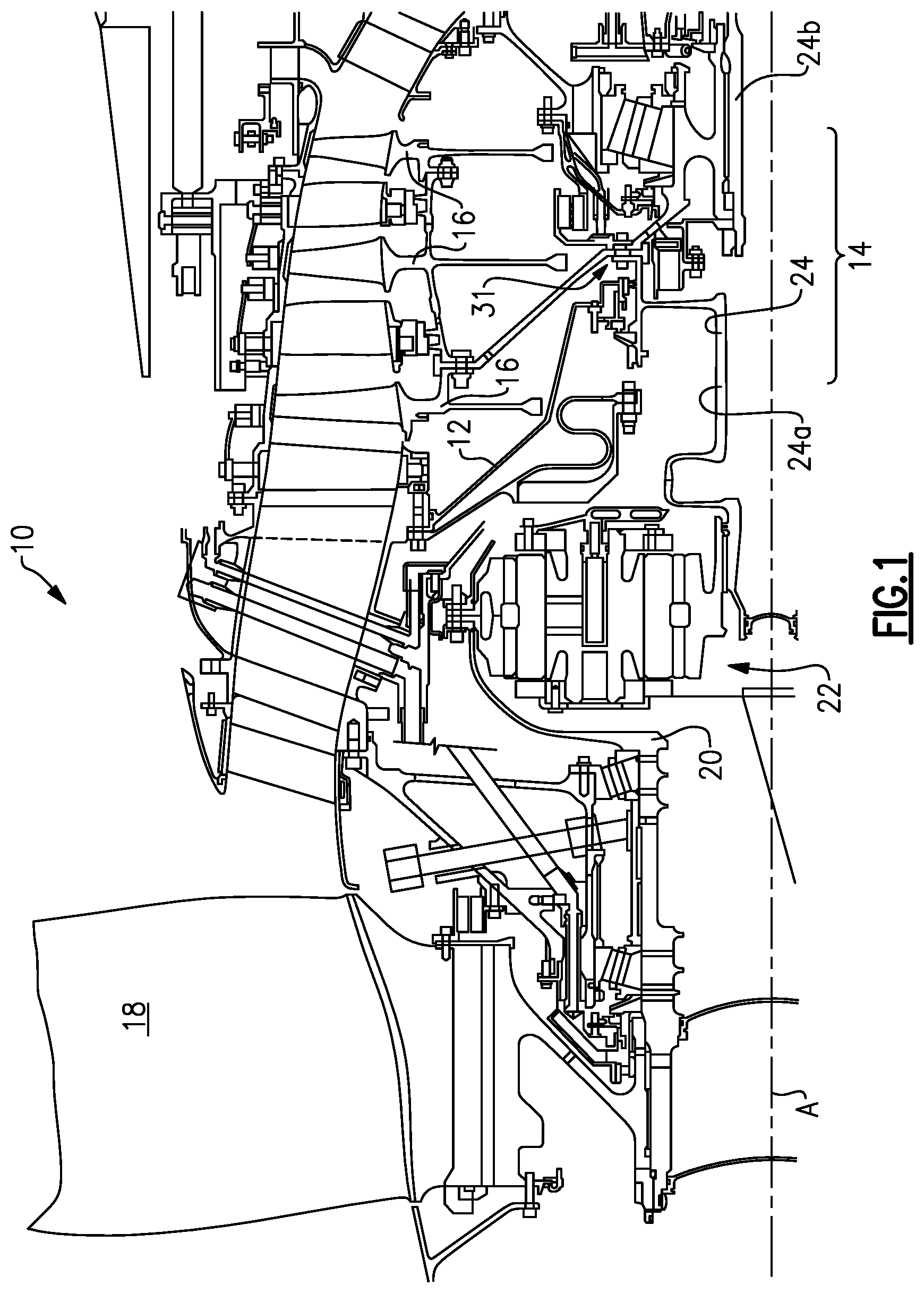
[0035] FIG. 1 is a partial cross-sectional view of a front portion of a gas turbine engine illustrating a turbo fan, epicyclic gear train and a compressor section.
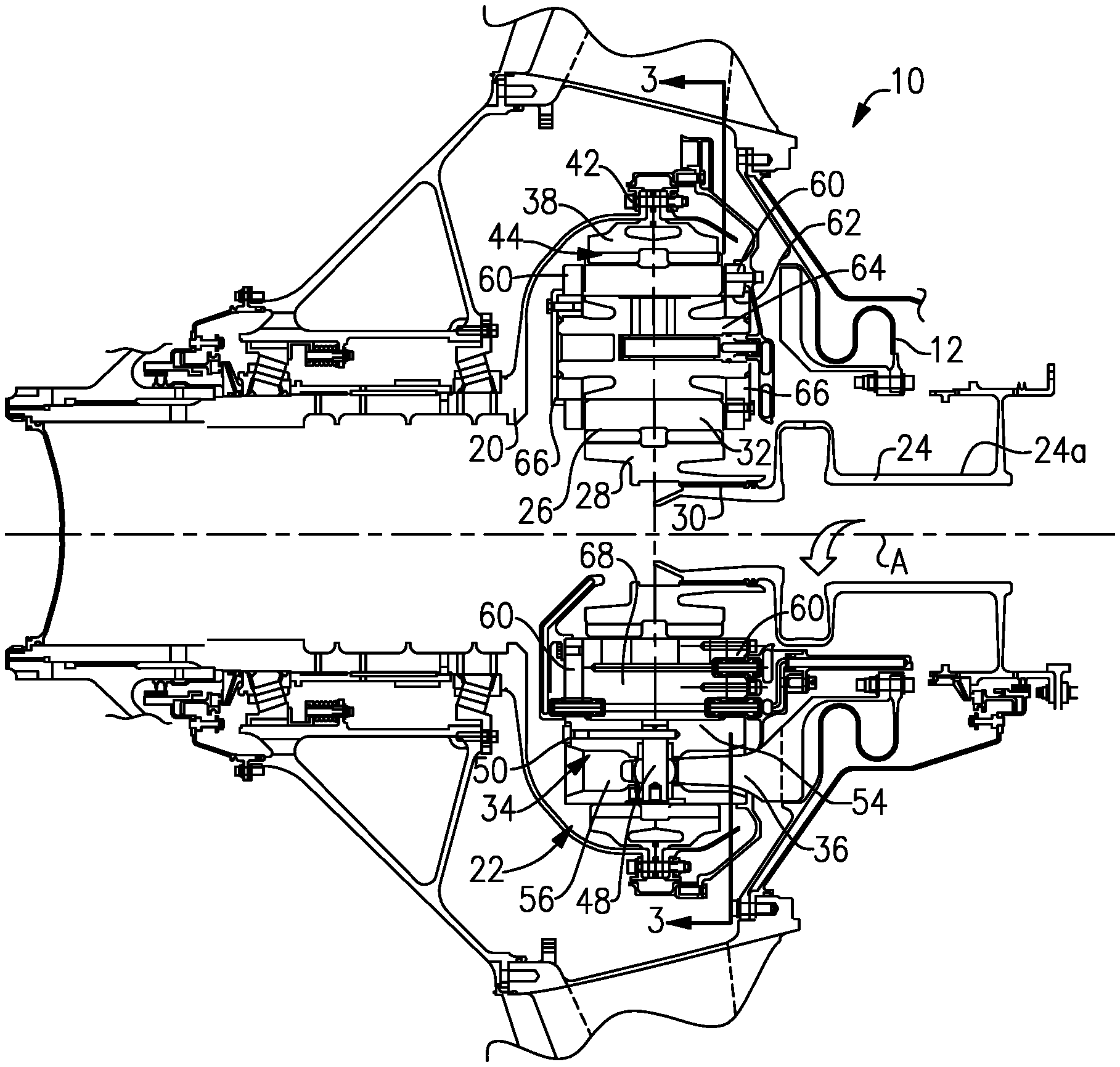
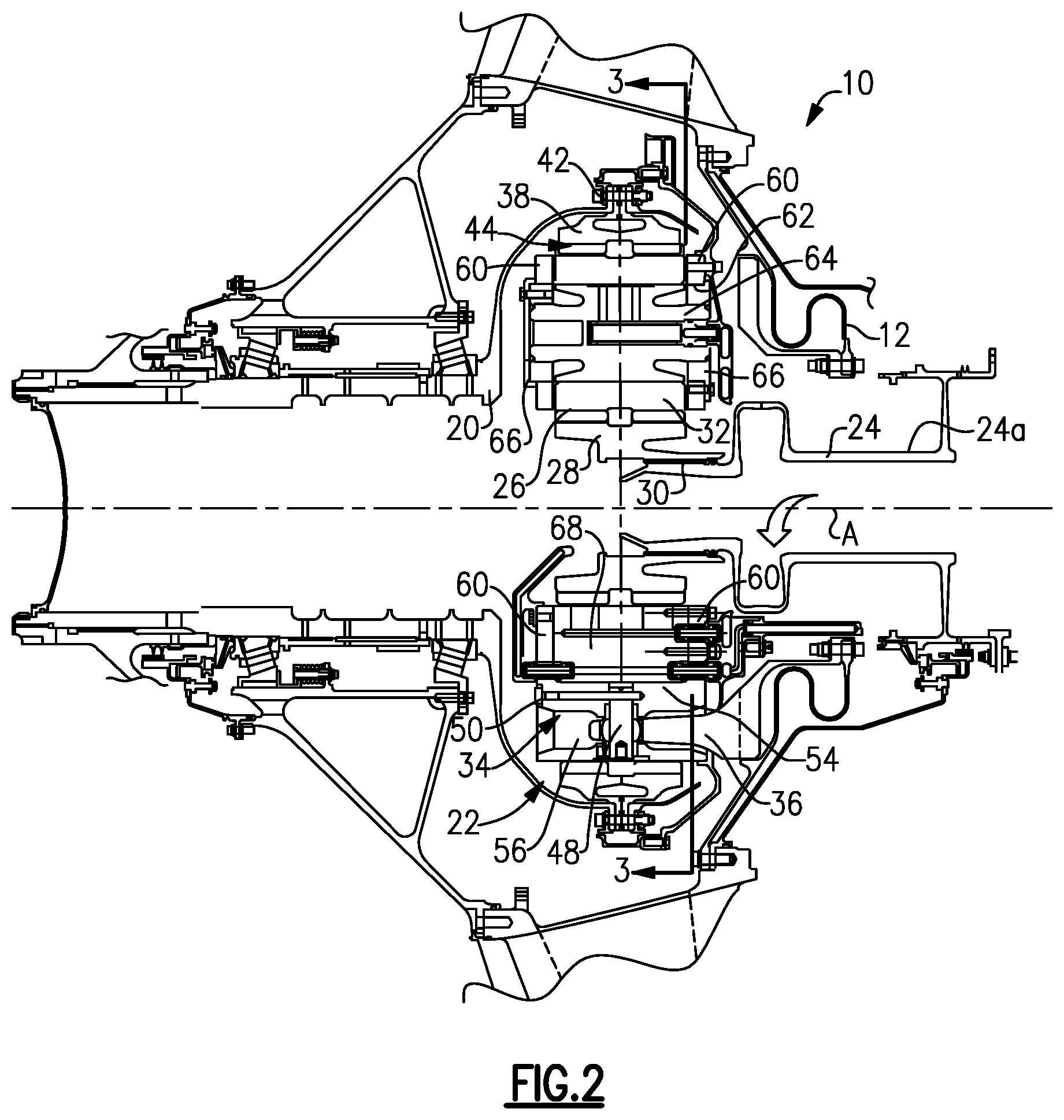
[0036] FIG. 2 is a cross-sectional view of the epicyclic gear train shown in FIG. 1.
[0037] FIG. 3 is an end view of the epicyclic gear train taken along line 3-3 in FIG. 2 with a pair of star gears shown in phantom in an installation position.
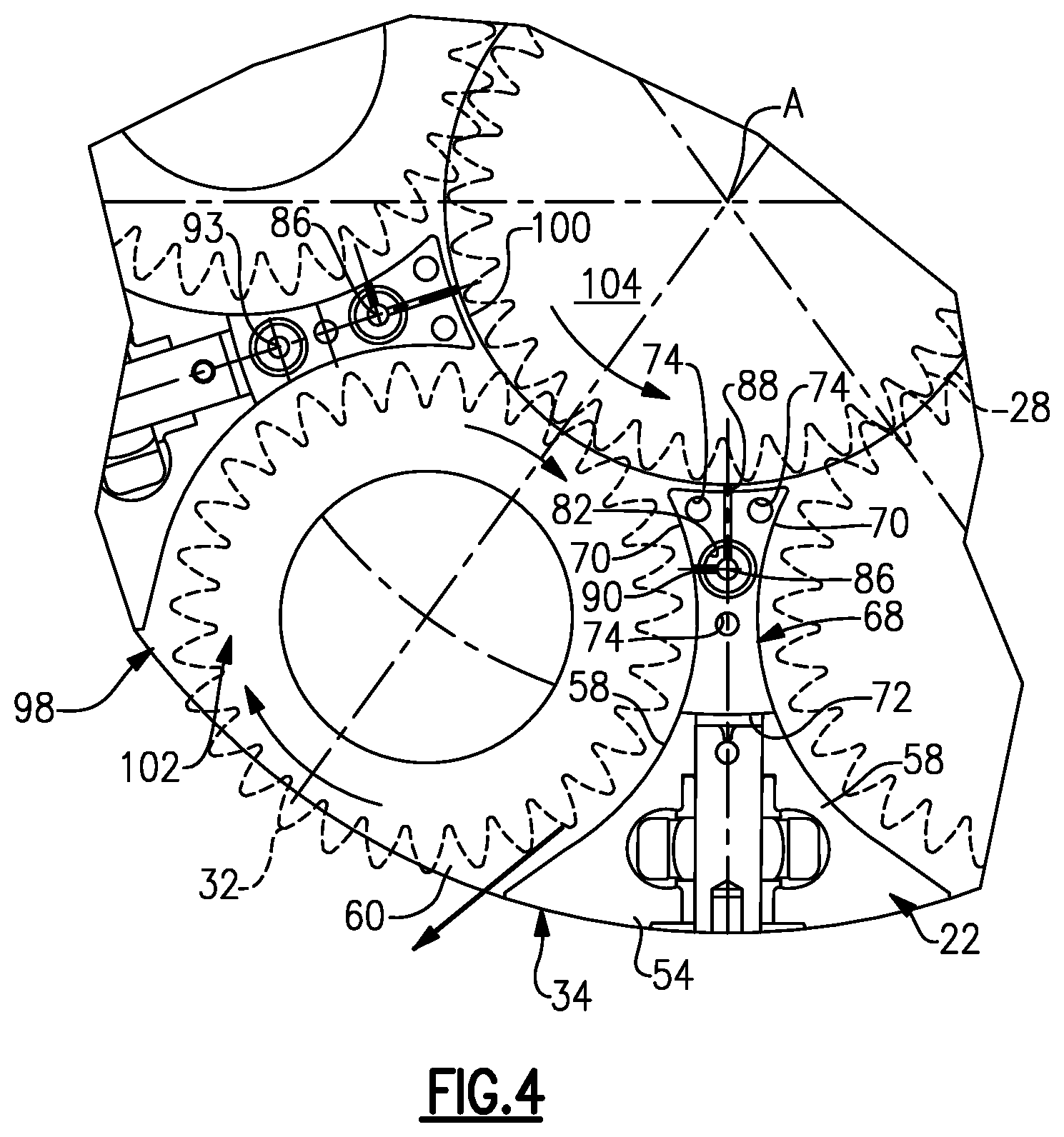
[0038] FIG. 4 is an enlarged view of a portion of the epicyclic gear train shown in FIG. 3 with a sun gear and star gears shown in phantom.
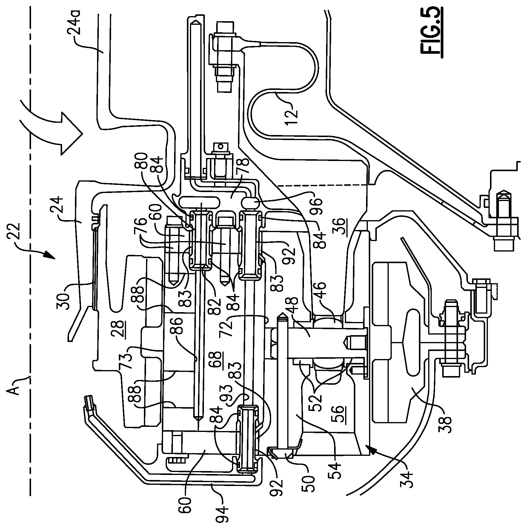
[0039] FIG. 5 is an enlarged view of a portion of the epicyclic gear train shown in FIG. 2.
DETAILED DESCRIPTION OF THE PREFERRED EMBODIMENT
[0040] A portion of a gas turbine engine 10 is shown schematically in FIG. 1. The turbine engine 10 includes a fixed housing 12 that is constructed from numerous pieces secured to one another. A compressor section 14 having compressor hubs 16 with blades are driven by a turbine shaft (not shown) about an axis A. A turbo fan 18 is supported on a turbo fan shaft 20 that is driven by a compressor shaft 24, which supports the compressor hubs 16, through an epicyclic gear train 22.
[0041] In the example arrangement shown, the epicyclic gear train 22 is a star gear train. Of course, the claimed invention also applies to other epicyclic gear trains such as a planetary arrangement. Referring to FIG. 2, the epicyclic gear train 22 includes a sun gear 28 that is connected to the compressor shaft 24, which provides rotational input, by a splined connection 30.
[0042] In the example arrangement shown, the compressor shaft is a two-part shaft having a first shaft 24a and a second shaft 24b. The first shaft 24a is connected to the second shaft 24b via a connection member 31, which is a bolt and nut in this example.
[0043] A carrier 34 is fixed to the housing 12 by a torque frame 36. The carrier 34 supports intermediate gears (which are star gears 32 in the arrangement shown) that are coupled to the sun gear 28 by meshed interfaces 26 between the teeth of the sun and star gears 28, 32. A ring gear 38 surrounds the carrier 34 and is coupled to the star gears 32 by meshed interfaces 44. The ring gear 38, which provides rotational output, is secured to the turbo fan shaft 20 by connection 42.
[0044] In one example, the torque frame 36 grounds the carrier 34 to the housing 12 in a known manner. For example, mounts 53 have apertures 56 receiving fingers of the torque frame 36, as shown in FIGS. 2 and 3. Pins 48 that extend through spherical bearings 46 and bushings 52 secure the fingers to the carrier 34. Fasteners 50 retain the pins 48 to the carrier 34.
[0045] The carrier 34 is a unitary structure manufactured from one piece for improved structural rigidity and ease of assembly. The carrier 34 includes spaced apart side walls 60 that are interconnected by the mounts 54, which are generally wedge-shaped members, as best shown in FIG. 3. The mounts 54 and side walls 60 are unitary with one another. The mounts 54 have opposing curved surfaces 58 that are in close proximity to the star gears 32 and generally follow the curvature of the teeth of the star gears 32 so that any oil on the curved surfaces 58 will likely find its way to the star gears 32 for additional lubrication.
[0046] The mounts 54 are circumferentially spaced about the carrier 34 to provide apertures 98 through which the star gears 32 extend to engage the ring gear 38. Returning to FIG. 2, the side walls 60 include holes 62 for receiving a journal bearing 64 that supports each of the star gears 32. Each journal bearing 64 is retained within the carrier 34 by retainers 66 fastened to the side walls 60.
[0047] Oil baffles 68 are arranged between the side walls 60 near each of the mounts 54, best shown in FIG. 2. Referring to FIGS. 4 and 5, the baffles 68 include ends 72 that abut the mounts 54, in the example shown. The baffles 68 also include opposing curved surfaces 70 arranged in close proximity to the star gears 28. The curved surfaces 58, 70 are contiguous with and adjoin one another, in the example shown, and provide gear pockets 102 that receive the star gears 32. A gear pocket 104, which receives the sun gear 28, is also provided between a surface 73 on each of the baffles 68 opposite the ends 72.
[0048] In one example, one of the side walls 60 includes holes 74 that receive fasteners 76 which secure each of the baffles 68 to the carrier 34. The baffles 68 include a lubrication passage provided by a primary passage 86 that fluidly communicates with a lubricant distributor 78. The lubricant distributor 78 is fed oil from a lubricant supply 96. In one example, the baffles 68 include openings 82 that receive a tube 80 extending through a hole 83 in the side wall 60. Seals 84 seal the tube 80 to the opening 82 and lubricant distributor 78. Other tubes 92 having seals 84 are used to provide oil to an external spray bar 94 through another lubrication passage (spray bar passage 93 that extends through one of the baffles 68). The external spray bar 94 is secured to the carrier 34 and sprays oil in the vicinity of the sun gear 28 near the splined connection 30 (shown in FIGS. 2 and 5).
[0049] The primary passage 86 is in communication with first and second passages 88, 90 that spray oil on the teeth of the sun and star gears 28, 32. In the example shown, the first and second passages 88, 90 are arranged ninety degrees from one another.
[0050] With the example baffles 68, lubricant distribution is integrated into the baffle so that separate components are eliminated. The baffles 68 can be constructed from a different, lighter weight material than the carrier 34.
[0051] The example carrier 34 can be constructed from one piece, which improves the structural integrity of the carrier. A central opening 100 is machined in at least one of the side walls 60 and provides the gear pocket 104. Gear pockets 102 are machined between the side walls 60 and mounts 54 for each of the star gears 32 and form apertures 98 at an outer circumference of the carrier 34. Referring to FIG. 3, the star gears 32 are inserted into the central opening 100 and moved radially outwardly so that they extend through the apertures 98 and are preferably in abutment with the mounts 54 (position indicated by dashed lines in FIG. 3). In this position, there is an adequate gap, t, between the teeth of adjacent star gears 32 to accommodate a width, w, of the end 72 of the baffles 68. Once the baffles 68 have been inserted, the star gears 32 can be repositioned, as shown by the solid lines, and the sun gear 28 can be inserted into the central opening 100 so that it meshes with the star gears 32. The baffles 68 are secured to the carrier 34 using fasteners 76. The tubes 80, 92 can be inserted and the rest of the lubricant distribution system can be connected.
[0052] Although a preferred embodiment of this invention has been disclosed, a worker of ordinary skill in this art would recognize that certain modifications would come within the scope of this invention. For that reason, the following claims should be studied to determine the true scope and content of this invention.
* * * * *
D00000
D00001
D00002
D00003
D00004
D00005
XML
uspto.report is an independent third-party trademark research tool that is not affiliated, endorsed, or sponsored by the United States Patent and Trademark Office (USPTO) or any other governmental organization. The information provided by uspto.report is based on publicly available data at the time of writing and is intended for informational purposes only.
While we strive to provide accurate and up-to-date information, we do not guarantee the accuracy, completeness, reliability, or suitability of the information displayed on this site. The use of this site is at your own risk. Any reliance you place on such information is therefore strictly at your own risk.
All official trademark data, including owner information, should be verified by visiting the official USPTO website at www.uspto.gov. This site is not intended to replace professional legal advice and should not be used as a substitute for consulting with a legal professional who is knowledgeable about trademark law.