Motor-Driven Door Latch for Vehicle
Nam; Jinwoo ; et al.
U.S. patent application number 16/441928 was filed with the patent office on 2020-09-10 for motor-driven door latch for vehicle. The applicant listed for this patent is Hyundai Motor Company, Kia Motors Corporation. Invention is credited to Jungho Han, Kyoung Taek Kwak, Jinwoo Nam.
| Application Number | 20200284069 16/441928 |
| Document ID | / |
| Family ID | 1000004145308 |
| Filed Date | 2020-09-10 |


View All Diagrams
| United States Patent Application | 20200284069 |
| Kind Code | A1 |
| Nam; Jinwoo ; et al. | September 10, 2020 |
Motor-Driven Door Latch for Vehicle
Abstract
A motor-driven door latch includes a catch part that is caught on a striker to lock the vehicle door to the vehicle body or is released from the striker so that the vehicle door can be opened from the vehicle body. A door locking and releasing part includes a main motor and is configured to apply a torque to the catch part through the main motor. An emergency door releasing part is provided with an auxiliary motor and is contacted with the door locking and releasing part by operation of the auxiliary motor. An inside emergency operating lever is connected with an inside handle installed at the vehicle door and is configured to receive an operation force of the inside handle to rotate and apply torque to the catch part through the emergency door releasing part and the door locking and releasing part.
| Inventors: | Nam; Jinwoo; (Seoul, KR) ; Kwak; Kyoung Taek; (Yongin-si, KR) ; Han; Jungho; (Seoul, KR) | ||||||||||
| Applicant: |
|
||||||||||
|---|---|---|---|---|---|---|---|---|---|---|---|
| Family ID: | 1000004145308 | ||||||||||
| Appl. No.: | 16/441928 | ||||||||||
| Filed: | June 14, 2019 |
| Current U.S. Class: | 1/1 |
| Current CPC Class: | E05B 77/12 20130101; E05B 81/34 20130101; E05B 81/16 20130101; E05Y 2900/531 20130101; E05B 85/06 20130101; E05B 81/90 20130101; B60J 5/04 20130101; E05B 81/76 20130101; E05B 81/36 20130101; E05B 81/06 20130101 |
| International Class: | E05B 81/90 20060101 E05B081/90; B60J 5/04 20060101 B60J005/04; E05B 81/16 20060101 E05B081/16; E05B 81/06 20060101 E05B081/06; E05B 81/34 20060101 E05B081/34; E05B 85/06 20060101 E05B085/06; E05B 81/76 20060101 E05B081/76; E05B 77/12 20060101 E05B077/12; E05B 81/36 20060101 E05B081/36 |
Foreign Application Data
| Date | Code | Application Number |
|---|---|---|
| Mar 6, 2019 | KR | 10-2019-0025607 |
Claims
1. A motor-driven door latch for a vehicle having a vehicle body and a vehicle door, the motor-driven door latch comprising: a catch part that is caught on a striker that is mounted on the vehicle to lock the vehicle door to the vehicle body or is released from the striker so that the vehicle door can be opened from the vehicle body; a door locking and releasing part that includes a main motor and is configured to apply a torque to the catch part through the main motor to allow the catch part to be locked to or released from the striker; an emergency door releasing part provided with an auxiliary motor and contacted with the door locking and releasing part by operation of the auxiliary motor when the main motor is not operated; an inside emergency operating lever connected with an inside handle installed at the vehicle door and configured to receive an operation force of the inside handle to rotate and apply torque to the catch part through the emergency door releasing part and the door locking and releasing part; and an outside emergency operating lever connected with an outside handle installed at the vehicle door and is configured to receive an operation force of the outside handle to rotate and to apply torque to the catch part through the emergency door releasing part and the door locking and releasing part.
2. The motor-driven door latch of claim 1, wherein the catch part comprises: a catch having a locking groove which the striker mounted on the vehicle body is caught in or separated from, the catch being installed to be rotatable; and a pawl installed to be rotatable so that the pawl is in close contact with the catch to limit the rotation of the catch or is separated from the catch to allow the catch to be freely rotatable.
3. The motor-driven door latch of claim 2, wherein the door locking and releasing part comprises: the main motor, which can rotate in a clockwise direction and an anticlockwise, the main motor including a first drive gear; a first driven gear engaged with the first drive gear; a pawl release lever coupled to the pawl to be integrally rotated; and an operating lever, which is engaged with the first driven gear and configured to receive the torque through the first driven gear to rotate the pawl release lever.
4. The motor-driven door latch of claim 3, wherein the auxiliary motor includes a second drive gear and wherein the emergency door releasing part comprises: a second driven gear engaged with the second drive gear; a master locking link, which installed to be rotatable, the master locking link contacted with the second driven gear so that rotation of the second driven gear is limited, the master locking link including a hook at one end portion thereof; and a pressurizing spring configured to apply an elastic force to the master locking link in order to rotate the master locking link in a direction.
5. The motor-driven door latch of claim 4, wherein: the inside emergency operating lever is installed to be rotatable and one end portion thereof is provided with a pressurizing flange; and the master locking link is provided with a rotation inducing flange, which corresponds to the pressurizing flange and is pressed by the pressurizing flange down to rotate the master locking link.
6. The motor-driven door latch of claim 4, wherein: the outside emergency operating lever is installed to be rotatable, wherein one end portion of the outside emergency operating lever is formed with a wire hole with which a wire is connected and another end portion of the outside emergency operating lever is formed with a first long hole; and the master locking link is provided with a pin shaft inserted into the first long hole.
7. The motor-driven door latch of claim 4, further comprising a key cylinder into which a key for the vehicle can be inserted to operate the vehicle.
8. The motor-driven door latch of claim 7, wherein: the key cylinder is provided with a key nut; the key nut is connected with one end portion of a key lever; and another end portion of the key lever is connected with the second driven gear.
9. The motor-driven door latch of claim 8, wherein: the key lever is formed with a second long hole at a lower portion thereof; and the second driven gear is provided with a coupling protrusion inserted into the second long hole.
10. The motor-driven door latch of claim 9, wherein: a protrusion is provided at an upper portion of the key lever; the key nut is provided with two first and second operating protrusions spaced from each other in a circumference direction; and a movable groove into which the protrusion is inserted to move is provided between the first and second operating protrusions.
11. The motor-driven door latch of claim 3, further comprising: two seating protrusions formed at the pawl release lever; and a pressurizing protrusion provided at the operating lever, wherein the pressurizing protrusion is seated on the seating protrusions and is configured to press and rotate the pawl release lever.
12. The motor-driven door latch of claim 1, further comprising a door latch controller configured to detect an operation of a handle or a button installed at the vehicle door and to apply an operation signal to the main motor.
13. The motor-driven door latch of claim 12, wherein the door latch controller is configured to detect a vehicle collision through a collision detecting sensor to apply the operation signal to the auxiliary motor when the main motor is inoperable due to vehicle collision.
14. A vehicle comprising: a vehicle body; a vehicle door; a striker that is mounted on the vehicle; a catch part that is caught on the striker to lock the vehicle door to the vehicle body or is released from the striker so that the vehicle door can be opened from the vehicle body; a door locking and releasing part that includes a main motor and is configured to apply a torque to the catch part through the main motor to allow the catch part to be locked to or released from the striker; an emergency door releasing part provided with an auxiliary motor and contacted with the door locking and releasing part by operation of the auxiliary motor when the main motor is not operated; an inside emergency operating lever connected with an inside handle installed at the vehicle door and configured to receive an operation force of the inside handle to rotate and apply torque to the catch part through the emergency door releasing part and the door locking and releasing part; and an outside emergency operating lever connected with an outside handle installed at the vehicle door and is configured to receive an operation force of the outside handle to rotate and to apply torque to the catch part through the emergency door releasing part and the door locking and releasing part.
15. The vehicle of claim 14, wherein the catch part comprises: a catch having a locking groove which the striker mounted on the vehicle body is caught in or separated from, the catch being installed to be rotatable; and a pawl installed to be rotatable so that the pawl is in close contact with the catch to limit the rotation of the catch or is separated from the catch to allow the catch to be freely rotatable.
16. The vehicle of claim 15, wherein the door locking and releasing part comprises: the main motor, which can rotate in a clockwise direction and an anticlockwise, the main motor including a first drive gear; a first driven gear engaged with the first drive gear; a pawl release lever coupled to the pawl to be integrally rotated; and an operating lever, which is engaged with the first driven gear and configured to receive the torque through the first driven gear to rotate the pawl release lever.
17. The vehicle of claim 16, wherein the auxiliary motor includes a second drive gear and wherein the emergency door releasing part comprises: a second driven gear engaged with the second drive gear; a master locking link, which installed to be rotatable, the master locking link contacted with the second driven gear so that rotation of the second driven gear is limited, the master locking link including a hook at one end portion thereof; and a pressurizing spring configured to apply an elastic force to the master locking link in order to rotate the master locking link in a direction.
18. The vehicle of claim 17, wherein: the inside emergency operating lever is installed to be rotatable and one end portion thereof is provided with a pressurizing flange; the outside emergency operating lever is installed to be rotatable, wherein one end portion of the outside emergency operating lever is formed with a wire hole with which a wire is connected and another end portion of the outside emergency operating lever is formed with a first long hole; and the master locking link is provided with a rotation inducing flange, which corresponds to the pressurizing flange and is pressed by the pressurizing flange down to rotate the master locking link, the master locking link also being provided with a pin shaft inserted into the first long hole.
19. The vehicle of claim 17, further comprising a key cylinder into which a key for the vehicle can be inserted to operate the vehicle, wherein: the key cylinder is provided with a key nut; the key nut is connected with one end portion of a key lever; and another end portion of the key lever is connected with the second driven gear.
20. The vehicle of claim 14, further comprising a door latch controller configured to detect an operation of a handle or a button installed at the vehicle door and to apply an operation signal to the main motor.
Description
CROSS-REFERENCE TO RELATED APPLICATIONS
[0001] This application claims priority to Korean Patent Application No. 10-2019-0025607, filed in the Korean Intellectual Property Office on Mar. 6, 2019, which application is hereby incorporated herein by reference.
TECHNICAL FIELD
[0002] The present invention relates to a motor-driven door latch for a vehicle.
BACKGROUND
[0003] Generally, a motor-driven door latch for a vehicle is used to lock or unlock a door to a vehicle body by using a motor for the convenience of the user.
[0004] In addition, an inside handle and an outside handle are respectively installed to allow the user to grasp the vehicle door and to easily operate the vehicle door, and a switch or the like is provided on the vehicle door for locking or releasing the motor-driven door latch.
[0005] However, in the conventional motor-driven door latch structure, when the motor is inoperable due to a vehicle collision or battery discharge, a structure or a device for releasing the door locking state through an appropriate door unlocking means has been became necessary.
[0006] The above information disclosed in this Background section is only for enhancement of understanding of the background of the invention and therefore it may contain information that does not form the prior art that is already known in this country to a person of ordinary skill in the art.
SUMMARY
[0007] The present invention relates to a motor-driven door latch for a vehicle. Particular embodiments of the invention relate to a motor-driven door latch for a vehicle capable of turning a door into an unlocked state using an emergency motor when a motor for opening and closing a door is inoperable.
[0008] Embodiments of the invention can provide a motor-driven door latch for a vehicle capable of easily releasing the door locking state even if a motor for opening and closing a door cannot be operated due to a collision accident or battery discharge and easily releasing the door locking state even by a key operation for a vehicle, thereby improving the merchantability and safety of the vehicle.
[0009] A motor-driven door latch for a vehicle according to an exemplary embodiment of the present invention may include, a catch part which is caught on a striker mounted on the vehicle to lock a door for a vehicle to a vehicle body or is released from the striker so that the door can be opened from the vehicle body. A door locking and releasing part includes a main motor and applies torque to the catch part through the main motor to allow the catch part to be locked to or released from the striker. An emergency door releasing part is provided with an auxiliary motor and contacted with the door locking and releasing part by the operation of the auxiliary motor when the main motor is not operated. An inside emergency operating lever is connected with an inside handle installed at the door for the vehicle and receives an operation force of the inside handle to rotate and apply torque to the catch part through the emergency door releasing part and the door locking and releasing part. An outside emergency operating lever is connected with an outside handle installed at the door for the vehicle and receives an operation force of the outside handle to rotate and apply torque to the catch part through the emergency door releasing part and the door locking and releasing part.
[0010] The catch part may comprise a catch having a locking groove which the striker mounted on the vehicle body is catch in or separated from and being installed to be rotatable; and a pawl installed to be rotatable and in close contact with the catch to limit the rotation of the catch or separated from the catch to allow the catch to be freely rotatable.
[0011] The door locking and releasing part may comprise the main motor, which can rotates in a clockwise and anticlockwise directions and includes a first drive gear; a first driven gear engaged with the first drive gear; a pawl release lever coupled to the pawl to be integrally rotated; and an operating lever, which is engaged with the first driven gear and receives the torque through the first driven gear to rotate the pawl release lever.
[0012] The emergency door releasing part may comprise the auxiliary motor including a second drive gear; a second driven gear engaged with the second drive gear; a master locking link, which installed to be rotatable, contacted with the second driven gear so that the rotation thereof is limited and includes a hook at one end portion thereof; and a pressurizing spring applying an elastic force to the master locking link in order to rotate the master locking link in a direction.
[0013] Two seating protrusions may be formed at the pawl release lever; and a pressurizing protrusion which seats on the seating protrusions, and presses and rotates the pawl release lever, may be provided at the operating lever.
[0014] A door latch controller detecting an operation of a handle or a button installed at the door for the vehicle and applying an operation signal to the main motor, may be further included.
[0015] The door latch controller may detect vehicle collision through a collision detecting sensor to apply an operation signal to the auxiliary motor when the main motor is inoperable due to vehicle collision.
[0016] The inside emergency operating lever may be installed to be rotatable and one end portion thereof is provided with a pressurizing flange; and the master locking link may be provided with a rotation inducing flange, which corresponds to the pressurizing flange and is pressed by the pressurizing flange down to rotate the master locking link.
[0017] The outside emergency operating lever may be installed to be rotatable, one end portion thereof may be formed with a wire hole with which a wire is connected and the other end portion thereof is formed with a first long hole; and the master locking link may be provided with a pin shaft inserted into the first long hole.
[0018] A key cylinder into which a key for a vehicle is inserted to operate may be provided with a key nut; the key nut may be connected with one end portion of a key lever; and the other end portion of the key lever may be connected with the second driven gear.
[0019] The key lever may be formed with a second long hole at a lower portion thereof; and the second driven gear may be provided with a coupling protrusion inserted into the second long hole.
[0020] A protrusion may be provided at an upper portion of the key lever; the key nut may be provided with two first and second operating protrusions spaced from each other in a circumference direction; and a movable groove into which the protrusion is inserted to move may be provided between the first and second operating protrusions.
[0021] In accordance with the motor-driven door latch for a vehicle according to an exemplary embodiment of the present invention, since a door for a vehicle can be locked a vehicle body in a stable manner by using a main motor and the locked door can be freely released from the vehicle body, the user can conveniently use a door for a vehicle.
[0022] When the main motor is inoperable due to a discharge or collision, it is possible to release the door locked to the vehicle body via an auxiliary motor and an inside handle or an outside handle, so that the use safety of the door for a vehicle can be improved.
[0023] When the main motor and the auxiliary motor are inoperable at the same time, a key for the vehicle can be used to release the door locked to the vehicle body, thereby further improving the use safety of the door for a vehicle.
BRIEF DESCRIPTION OF THE DRAWINGS
[0024] These drawings are for reference purposes only and are not to be construed as limiting the technical idea of the present invention to the accompanying drawings.
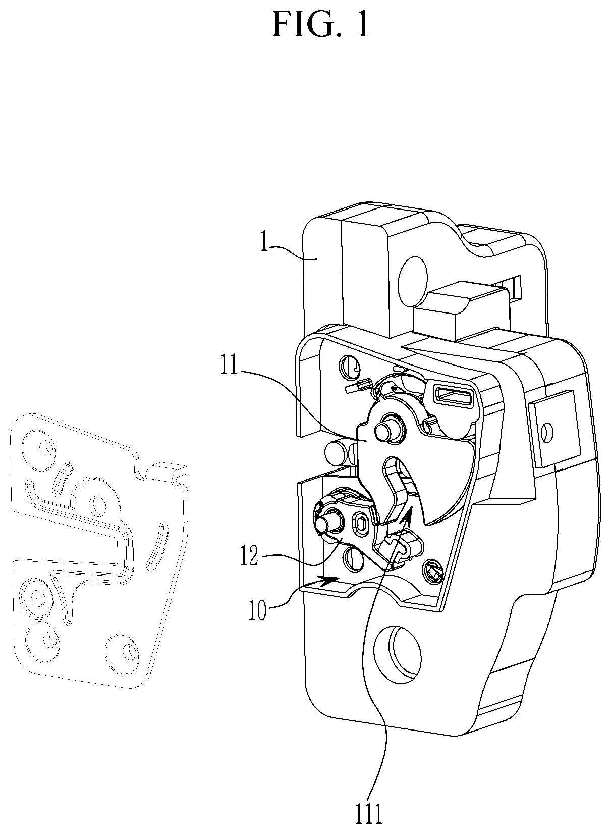
[0025] FIG. 1 is a side view of a motor-driven door latch for a vehicle according to an exemplary embodiment of the present invention.
[0026] FIG. 2 is a front view of the motor-driven door latch for the vehicle according to an exemplary embodiment of the present invention.
[0027] FIG. 3 is an exploded perspective view of a catch part of the motor-driven door latch for the vehicle according to an exemplary embodiment of the present invention.
[0028] FIG. 4 is a perspective view showing coupling state of a pawl and a pawl release lever of the motor-driven door latch for the vehicle according to an exemplary embodiment of the present invention.
[0029] FIG. 5 is an exploded perspective view of a door locking and releasing part and an emergency door releasing part of the motor-driven door latch for the vehicle according to an exemplary embodiment of the present invention.
[0030] FIG. 6 is an operational explanatory diagram of the door locking and releasing part of the motor-driven door latch for the vehicle according to an exemplary embodiment of the present invention.
[0031] FIGS. 7 and 8 are operational explanatory diagrams of the emergency door releasing part of the motor-driven door latch for the vehicle according to an exemplary embodiment of the present invention.
[0032] FIG. 9 is an operational explanatory diagram of an inside emergency operating lever and a master locking link of the motor-driven door latch for the vehicle according to an exemplary embodiment of the present invention.
[0033] FIG. 10 is an operational explanatory diagram of an outside emergency operating lever and the master locking link of the motor-driven door latch for the vehicle according to an exemplary embodiment of the present invention.
[0034] FIG. 11 is an operational explanatory diagram when operating a key for a vehicle of the motor-driven door latch for the vehicle according to an exemplary embodiment of the present invention.
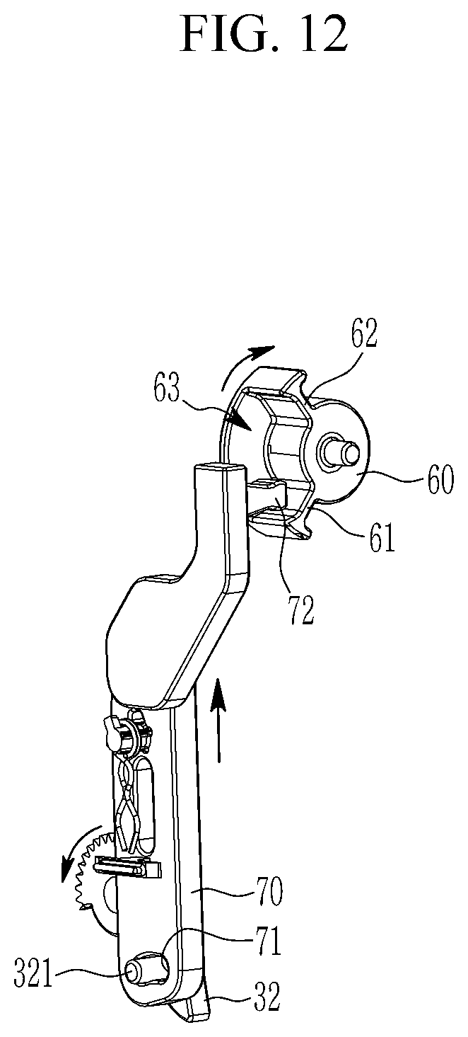
[0035] FIG. 12 is an operational explanatory diagram of a key nut and a key lever of the motor-driven door latch for the vehicle according to an exemplary embodiment of the present invention.
[0036] The following reference numerals can be used in conjunction with the drawings: [0037] 1: first base plate [0038] 2: second base plate [0039] 10: catch part [0040] 11: catch [0041] 12: pawl [0042] 20: door locking and releasing part [0043] 21: main motor [0044] 22: first driven gear [0045] 23: pawl release lever [0046] 24: operating lever [0047] 30: emergency door releasing part [0048] 31: auxiliary motor [0049] 32: second driven gear [0050] 33: master locking link [0051] 34: pressurizing spring [0052] 40: inside emergency operating lever [0053] 50: outside emergency operating lever [0054] 60: key nut [0055] 70: key lever
DETAILED DESCRIPTION OF ILLUSTRATIVE EMBODIMENTS
[0056] The present invention will be described more fully hereinafter with reference to the accompanying drawings, in which exemplary embodiments of the invention are shown.
[0057] As those skilled in the art would realize, the described embodiments may be modified in various different ways, all without departing from the spirit or scope of the present invention.
[0058] The drawings and description are to be regarded as illustrative in nature and not restrictive. Like reference numerals designate like elements throughout the specification.
[0059] Since size and thickness of each component illustrated in the drawings are arbitrarily represented for convenience in explanation, the present invention is not particularly limited to the illustrated size and thickness of each component and the thickness is enlarged and illustrated in order to clearly express various parts and areas.
[0060] In the following description, dividing names of components into first, second and the like is to divide the names because the names of the components are the same as each other and an order thereof is not particularly limited.
[0061] Throughout the specification, unless explicitly described to the contrary, the word "comprise" and variations such as "comprises" or "comprising", will be understood to imply the inclusion of stated elements but not the exclusion of any other elements.
[0062] Referring to FIGS. 1 to 5, a motor-driven door latch for a vehicle according to an exemplary embodiment of the present invention may include a catch part 10 which is caught on a striker mounted on the vehicle to lock a door for a vehicle to the vehicle body or is released from the striker so that the door can be opened from the vehicle body; a door locking and releasing part 20 which applies torque to the catch part 10 to allow the catch part 10 to be locked to or released from the striker; and an emergency door releasing part 30 that allows the door locked to the vehicle body to be released from the vehicle body when the door locking and releasing part 20 is not operated due to battery discharge or collision, and the like.
[0063] The catch part 10 may include a catch 11, which is rotatably mounted on one side of a first base plate 1 and has a locking groove in which the striker mounted on the vehicle body is inserted into or separated from and a pawl 12, which is mounted on the first base plate 1 to be rotatable and is in close contact with the catch 11 to limit the rotation of the catch 11 or separated from the catch 11 to allow the catch 11 to be freely rotatable.
[0064] The door locking and releasing part 20 may include a main motor 21, which is mounted on a second base plate 2, rotatable in a clockwise and anticlockwise directions, and includes a first drive gear 211. A first driven gear 22 is engaged with the first drive gear 211. A pawl release lever 23 is disposed with the first base plate 1 interposed therebetween and coupled to the pawl 12 to be integrally rotated (referring to FIG. 4). An operating lever 24 is engaged with the first driven gear 22 and rotates while receiving a torque from the first driven gear 22 to rotate the pawl release lever 23.
[0065] The emergency door releasing part 30 may include an auxiliary motor 31 for emergency mounted on the first base plate 1 and provided with a second drive gear 311; a second driven gear 32 engaged with the second drive gear 311; a master locking link 33 of which one end portion is rotatably mounted on the first base plate 1 and the other end portion is provided with a hook 331; and a pressurizing spring 34 for pressurizing the master locking link 33 to be rotated in a clockwise direction.
[0066] When the user operates a release handle or a button mounted on the door, a door latch controller detects this to apply an operation signal to the main motor 21 to operate the main motor 21.
[0067] Referring to FIG. 6, the first drive gear 211 and the first driven gear 22 rotate respectively by driving the main motor 21, the operating lever 24 engaged with the first driven gear 22 is rotated to rotate the pawl release lever 23, and the pawl 12 rotates together by the rotation of the pawl release lever 23 and is spaced from the catch 11, so that the catch 11 can freely rotate, thereby releasing the door locked the vehicle body and opening the door.
[0068] Therefore, when the user pushes or pulls the door while holding the inside handle or the outside handle installed on the door, the door is opened while one side of the door is supported by the vehicle body and the door is being rotated.
[0069] The pawl release lever 23 may be provided with two seating protrusions 231 and the operating lever 24 may be provided with a pressurizing protrusion 241 which is seated on the seating protrusions 231 to press and rotate the pawl release lever 23.
[0070] On the other hand, if the main motor fails due to a vehicle collision, the door latch controller senses the collision through a collision detecting sensor and applies an actuating signal to the auxiliary motor 31.
[0071] Thus, as shown FIGS. 7 and 8, the operation of the auxiliary motor 31 rotates the second drive gear 311 and the second driven gear 32 respectively, and the master locking link 33 is released from the second driven gear 32 by the rotation of second driven gear 32 and rotates in a clockwise by the elastic restoring force of the pressurizing spring 34, so that a door lock release preparation state where a hook 331 of the master locking link 33 is hung on the seating protrusions of the pawl release lever 23 is made.
[0072] In the door lock release preparation state, if a passenger pulls the inside handle, the inside emergency operating lever 40 connected with the inside handle through a wire 41 is rotated.
[0073] The inside emergency operating lever 30 may be installed on the second base plate 2 to be rotatable and one end portion thereof may be provided with a pressurizing flange 42, as shown in FIG. 9.
[0074] Further, in the master locking link 33, a rotation inducing flange 332 may be formed in a circular arc shape corresponding to the pressurizing flange 42. The pressurizing flange 42 is integrally rotated by the rotation of the inside emergency operating lever 40 to press the rotation inducing flange 332 of the master locking link 33, so that the master locking link 33 rotates in a clockwise direction from the door lock release preparation state where the master locking link 33 is hung on the seating protrusions 231 of the pawl release lever 23 to rotate the pawl release lever 23 in an anticlockwise.
[0075] The pawl 12 is rotated by the rotation of the pawl release lever 23 together and thus separated from the catch 11, so that the catch 11 can be freely rotated. Thus, the door locked to the vehicle body is released from it and can be opened.
[0076] On the other hand, in the door lock release preparation state, if the user pulls the outside handle, as shown in FIG. 10, an outside emergency operating lever 50 connected with the outside handle through a wire is rotated.
[0077] The outside emergency operating lever 50 may be installed on the second base plate 2 to be rotatable, one end portion thereof may be formed with a wire hole 51 with which a wire is connected and the other end portion thereof may be formed with a first long hole 52 into which a pin shaft 333 provided at the master locking link 33 is inserted.
[0078] When the outside emergency operating lever 50 is rotated, the master locking link 33 is further rotated in a clockwise direction from the door lock release preparation state by the rotation of the outside emergency operating lever 50 to rotate the pawl release lever 23 in an anticlockwise.
[0079] The pawl 12 is rotated by the rotation of the pawl release lever 23 together to be separated from the catch 11 to allow the catch 11 to freely rotate, so that the door locked to the vehicle body is released from it and the door can be opened.
[0080] On the other hand, when the battery of the vehicle is discharged and the main motor 21 and the auxiliary motor 31 become inoperable, if the user inserts a key for a vehicle a key hole to rotate a key cylinder, as shown in FIG. 11, a key nut 60 provided at the key cylinder is rotated and a key lever 70 is raised by the rotation of the key nut 60 to rotate the second driven gear 32. Thus, the rotation of the second driven gear 32 allows the master locking link 33 to be released from the second driven gear 32. The master locking link 33 is rotated by the elastic restoring force of the pressurizing spring 34 in a clockwise direction, so that the door lock release preparation state where the hook 331 of the master locking link 33 is hung on the seating protrusions 231 of the pawl release lever 23 is achieved.
[0081] In the door lock release preparation state, when the user pulls the outside handle, as described above, the outside emergency operating lever 50 is rotated so that the door can be opened.
[0082] Referring to FIG. 12, a second long hole 71 may be formed at a lower portion of the key lever, a coupling protrusion 321 inserted into the second long hole 71 may be provided at the second driven gear 32, a protrusion 72 may be provided on an upper portion of the key lever 70, two operating protrusions 61 and 62 spaced from each other in a circumference direction may be provided at the key nut 60 and a movable groove 63 which the protrusion 72 is inserted into and can move therein may be provided between the first and second operating protrusions 61 and 62.
[0083] That is, when the auxiliary motor 31 is operated and the second driven gear 32 is rotated, the key lever 70 moves up and down by the rotation of the second driven gear 32 but the protrusion 72 of the key lever 70 moves up and down in the movable groove 63 of the key nut 60, so that the protrusion 72 of the key lever 70 is not contacted with the first and second operating protrusions 61 and 62 of the key nut 60.
[0084] On the other hand, when the key nut 60 is rotated by operation of the key for a vehicle, the key lever 70 is contacted with the first operating protrusion 61 to be forcibly raised up, so that the second driven gear 32 is forcibly rotated by the key lever 70 and the master locking link 33 rotates also, thereby achieving the door lock release preparation state.
[0085] While this invention has been described in connection with what is presently considered to be practical exemplary embodiments, it is to be understood that the invention is not limited to the disclosed embodiments. On the contrary, it is intended to cover various modifications and equivalent arrangements included within the spirit and scope of the appended claims.
* * * * *
D00000
D00001
D00002
D00003
D00004
D00005
D00006
D00007
D00008
D00009
D00010
D00011
D00012
XML
uspto.report is an independent third-party trademark research tool that is not affiliated, endorsed, or sponsored by the United States Patent and Trademark Office (USPTO) or any other governmental organization. The information provided by uspto.report is based on publicly available data at the time of writing and is intended for informational purposes only.
While we strive to provide accurate and up-to-date information, we do not guarantee the accuracy, completeness, reliability, or suitability of the information displayed on this site. The use of this site is at your own risk. Any reliance you place on such information is therefore strictly at your own risk.
All official trademark data, including owner information, should be verified by visiting the official USPTO website at www.uspto.gov. This site is not intended to replace professional legal advice and should not be used as a substitute for consulting with a legal professional who is knowledgeable about trademark law.