Device For Attachment To A Bridge Support Bracket
Roberts; Eric
U.S. patent application number 16/295459 was filed with the patent office on 2020-09-10 for device for attachment to a bridge support bracket. The applicant listed for this patent is Eric Roberts. Invention is credited to Eric Roberts.
| Application Number | 20200283971 16/295459 |
| Document ID | / |
| Family ID | 1000004007858 |
| Filed Date | 2020-09-10 |


View All Diagrams
| United States Patent Application | 20200283971 |
| Kind Code | A1 |
| Roberts; Eric | September 10, 2020 |
DEVICE FOR ATTACHMENT TO A BRIDGE SUPPORT BRACKET
Abstract
A device for attachment to a bridge support bracket is adapted to be connected to an end of a support bracket horizontal component and to an end of a support bracket vertical component. The device comprises a support adapted to be attached to the end of the horizontal component, a sliding tube adapted to be attached to the end of the vertical component, and a mounting tube attached to the support for mounting the sliding for sliding movement relative to the support. A slot is in the side of the mounting tube, and a nub is attached to the sliding tube and extends through the slot. The nub has a threaded opening therein, and a threaded rod extends through and engages the threaded opening, the threaded rod being mounted for rotation but not vertical movement relative to the support, for moving the vertical piece vertically relative to the support.
| Inventors: | Roberts; Eric; (Genoa City, WI) | ||||||||||
| Applicant: |
|
||||||||||
|---|---|---|---|---|---|---|---|---|---|---|---|
| Family ID: | 1000004007858 | ||||||||||
| Appl. No.: | 16/295459 | ||||||||||
| Filed: | March 7, 2019 |
| Current U.S. Class: | 1/1 |
| Current CPC Class: | E01D 19/125 20130101; E01D 19/10 20130101 |
| International Class: | E01D 19/12 20060101 E01D019/12; E01D 19/10 20060101 E01D019/10 |
Claims
1. A device for attachment to a bridge support bracket, the support bracket including a horizontal component, a vertical component, and an angled component attached at one end to an end of the horizontal component, and another end of the angled component is attached to an end of the vertical component, the device being adapted to be connected to the other end of the horizontal component and to the other end of the vertical component, the device comprising: a support adapted to be attached to the other end of the horizontal component, a vertical piece adapted to be attached to the other end of the vertical component, mounting means attached to the support for mounting the vertical piece for sliding movement relative to the support, and moving means attached to and between the support and the vertical piece for moving the vertical piece vertically relative to the support.
2. The device in accordance with claim 1 wherein the mounting means is a mounting tube, and the vertical piece is a sliding tube received in and slidable relative to the mounting tube.
3. The device in accordance with claim 2 wherein the moving means comprises a slot in the side of the mounting tube, a nub attached to the sliding tube and extending through the slot, the nub having a nub threaded opening therein, and a threaded rod extending through and engaging the nub threaded opening, the threaded rod being mounted for rotation but not vertical movement relative to the support, so that rotation of the threaded rod slides the nub and sliding tube relative to the mounting tube and the support to vary the combined length of the support bracket vertical component and the vertical piece relative to the horizontal component to change the angle of the horizontal component relative to the vertical component.
4. The device in accordance with claim 1 wherein the support comprises two spaced apart support plates, and wherein the threaded rod is mounted for rotation relative to the support by the two spaced apart support plates, each support plate being located on opposite sides of the nub, with a threaded rod opening in each support plate, the respective ends of the threaded rod each passing through the respective plate threaded rod openings, and a threaded rod nut fixed to each respective end of the threaded rod for preventing sliding movement of the rod relative to the support, with at least one nut being adapted to be rotated to in turn rotate the threaded rod relative to the support.
5. The device in accordance with claim 1 wherein the vertical piece is adapted to be attached to the other end of the support bracket vertical component by having an attachment opening through one end of the vertical piece, and a bolt that passes through the attachment opening and through the other end of the vertical component in order to secure the other end of the vertical component to the end of the vertical piece.
6. A device for attachment to a bridge support bracket, the device being adapted to be connected to an end of a support bracket horizontal component and to an end of a support bracket vertical component, the device comprising a support adapted to be attached to the end of the horizontal component, a sliding tube adapted to be attached to the end of the vertical component, and a mounting tube attached to the support for mounting the sliding for sliding movement relative to the support, the device having a slot is in the side of the mounting tube, and the device further including a nub attached to the sliding tube and extending through the slot, the nub having a threaded opening therein, and a threaded rod extending through and engaging the threaded opening, the threaded rod being mounted for rotation but not vertical movement relative to the support, for moving the vertical piece vertically relative to the support.
Description
BACKGROUND
[0001] This application is directed to bridge building, and, more particularly, to the use of bridge overhang support brackets used in bridge construction.
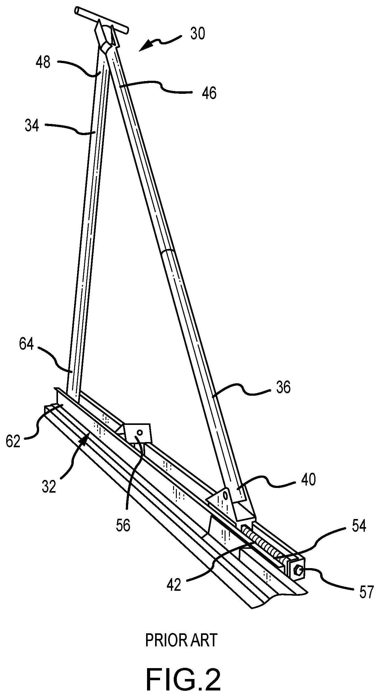
[0002] As illustrated in FIG. 1, modern-day bridges use steel or concrete I-beams 10 to support bridge loads. After placement of the I-beams, concrete roadways 14 are formed on top of the I-beams. Further, a portion 18 of the concrete roadway extends over the outside edges of the I-beam. When constructing the bridge, concrete forms 22 and the concrete 18 are supported by bridge overhang support brackets 30 secured to the I-beam 10. Each support bracket 30 includes a horizontal component 32, a vertical component 34, and an angled component 36 attached at one end 40 to an end 42 of the horizontal component, and another end 46 attached to an end 48 of the vertical component 34. Conventionally, the various ends are attached to each other with nuts and bolts, with or without the use of various adapters. The vertical component 34 is also attached at one end 64 to an end 62 of the horizontal component. More specifically, as illustrated in FIG. 2, the typical support bracket vertical 34 and angled 36 components are telescoping tubes, and the horizontal component 32 is made from spaced apart steel plates 49 and 51 (see FIG. 5). By varying the amount of telescoping of the vertical and angled components, and the point of attachment of the vertical and angled components to the horizontal component, various support bracket dimensions can be accommodated in order to allow the bridge overhang support bracket 30 to be used with different bridge installations.
[0003] As shown in FIGS. 1 and 3, the connection of the support bracket 30 to the I-beam 10 begins with the placement of a hanger 50 on the top of the I-beam 10. The hanger 50 is secured to the I-beam 10 in a conventional fashion, such as by attaching the rear of the hanger to the back side of the I-beam 10, as shown in FIG. 3, and a hanger end clip 52 is positioned just at the edge of the I-beam where the support bracket 30 is to be positioned.
[0004] The next step in this process is to support the bridge overhang support bracket 30 on the side of the I-beam 10 so a coil rod 54 can be inserted through an opening (not shown) in the hangar clip 52, and also inserted into a support bracket bolt holder 56 in the support bracket 30. After being inserted through openings in the hanger clip 52 and the bolt holder 56, the coil rod 54 is then secured in place by coil nuts 58 on the ends of the coil rod 54.
[0005] Once in place, it is not uncommon for a bridge construction worker to need to adjust the relative lengths of the support bracket components, in order to adjust the relative angles between the bracket sides. More specifically, the horizontal component 32 may not end up being horizontal, so, with other points of attachment being fixed, by varying one point of attachment the relative angle between the vertical component 34 and the horizontal component 32 can changed to result in a truly level horizontal component.
[0006] Two examples of how this is currently accomplished are as follows. As shown in FIG. 2, it is common to have a threaded bolt 54 within the horizontal component 32, with a bolt head 57 accessible from outside the support bracket 30 for rotating the threaded bolt 54. The bolt in turn is received in a clip 58 that holds an end of the angled component 36 inside the horizontal component 32. By rotating the threaded bolt 54, the point of attachment of the angled component relative to the horizontal component can be varied. In another bridge support bracket design, as illustrated in U.S. Pat. No. 7,032,268, the vertical component is a threaded rod, which can be turned in order to vary the threaded rod points of attachment between the horizontal component and the angled component, in order to change the relative angles between the components.
SUMMARY
[0007] Disclosed is a device for attachment to a bridge support bracket. The device is adapted to be connected to an end of a support bracket horizontal component and to an end of a support bracket vertical component. The device comprises a support adapted to be attached to the end of the horizontal component, a sliding tube adapted to be attached to the end of the vertical component, and a mounting tube attached to the support for mounting the sliding for sliding movement relative to the support. A slot is in the side of the mounting tube, and a nub is attached to the sliding tube and extends through the slot. The nub has a threaded opening therein, and a threaded rod extends through and engages the threaded opening, the threaded rod being mounted for rotation but not vertical movement relative to the support, for moving the vertical piece vertically relative to the support.
DRAWINGS
[0008] FIG. 1 is a side perspective view illustrating bridge construction. An I-beam is show, with an attached bridge support bracket, and forming for the concrete bridge.
[0009] FIG. 2 is a side perspective view illustrating further details of the bridge support bracket.
[0010] FIG. 3 is a side view of a portion of an I-beam, a hanger, and a coil rod passing through a hanger end clip and a bracket bolt holder. A portion of a vertical component of the bridge support bracket is shown attached to a bridge support bracket horizontal component.
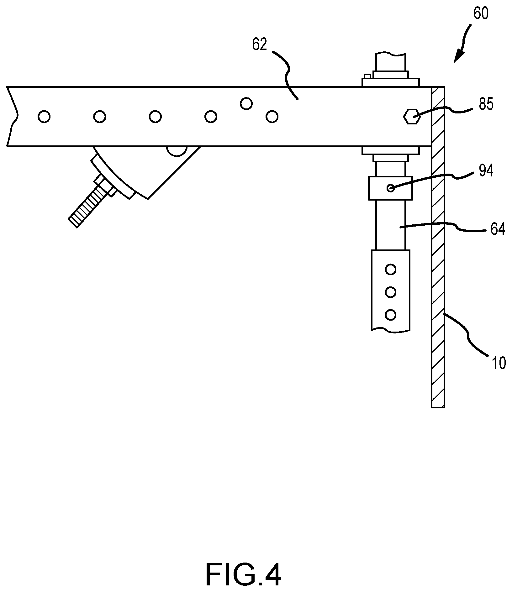
[0011] FIG. 4 is an enlarged side view of a portion of the support bracket illustrated in FIG. 4, together with an adjustment device according to this disclosure.
[0012] FIG. 5 is a top perspective view illustrating the adjustment device of this disclosure being slid onto the end of the horizontal component of the bridge support bracket.
[0013] FIG. 6 is a top perspective view of the adjustment device attached to the end of the horizontal component of the bridge support bracket.
[0014] FIG. 7 is a side perspective view of the adjustment device according to this disclosure.
[0015] FIG. 8 is a side perspective view of another side of the adjustment device shown in FIG. 7.
[0016] FIG. 9 is an enlarged side perspective view of the adjustment device shown in FIG. 7.
[0017] FIG. 10 is an end view of the adjustment device shown in FIG. 7.
[0018] FIG. 11 is a side perspective view of the adjustment device, with a sliding tube shown in a first position relative to a holding tube.
[0019] FIG. 12 is a side perspective view similar to FIG. 11, only showing the sliding to the different second position relative to the holding to.
[0020] Before one embodiment of the invention is explained in detail, it is to be understood that the invention is not limited in its application to the details of the construction and the arrangements of components set forth in the following description or illustrated in the drawings. The invention is capable of other embodiments and of being practiced or being carried out in various ways. Also, it is to be understood that the phraseology and terminology used herein is for the purpose of description and should not be regarded as limiting. Use of "including" and "comprising" and variations thereof as used herein is meant to encompass the items listed thereafter and equivalents thereof as well as additional items. Use of "consisting of" and variations thereof as used herein is meant to encompass only the items listed thereafter and equivalents thereof. Further, it is to be understood that such terms as "forward", "rearward", "left", "right", "upward" and "downward", etc., are words of convenience in reference to the drawings and are not to be construed as limiting terms.
DESCRIPTION OF A PREFERRED EMBODIMENT
[0021] Although the disclosure hereof is detailed and exact to enable those skilled in the art to practice the invention, the physical embodiments herein disclosed merely exemplify the invention which may be embodied in other specific structures. While the preferred embodiment has been described, the details may be changed without departing from the invention, which is defined by the claims.
[0022] Illustrated in the drawings is a metal device 60 for attachment to a bridge overhang support bracket 30. The device 60 according to this disclosure is adapted, as shown in FIG. 4, to be connected to the other end 62 of the horizontal component 32 and to the other end 64 of the vertical component 34, so that the points of attachment between the horizontal component and the angled component can be varied in order to change the relative angles between the components. Access to the device 60 is at the end of the horizontal component by the I-beam, thus providing bridge builders with a ready and convenient method of leveling the support bracket horizontal component 32.
[0023] The device 60 according to this disclosure, as shown in FIG. 9, comprises a support 70 adapted to be attached to the other end 62 of the horizontal component 32, a vertical piece 72 adapted to be attached to the other end 64 of the vertical component 34, mounting means 74 attached to the support 70 for mounting the vertical piece 72 for sliding movement relative to the support 70, and moving means 76 attached to and between the support 70 and the vertical piece 72 for moving the vertical piece 72 vertically relative to the support 70.
[0024] More specifically, as shown in FIG. 7, the support is in the form of two spaced apart rectangular plates 78 and 79. The spacing of the support plates 78 and 79 is such that it allows the end plates to snuggly slide along the top 80 and bottom 82 of the horizontal component 32, as illustrated in FIGS. 6 and 7. The spaced apart plates 49 and 51 at the end of the horizontal component 32 provides room for the mounting of the vertical piece 72 and the mounting means 74, and the support plates 78 and 79 hold the device 60 in place on the horizontal component 32.
[0025] In the illustrated embodiment, the mounting means is in the form of a square mounting tube 74, and the vertical piece is a sliding tube 72 received in and slidable relative to the mounting tube 74. More specifically, the mounting tube 74 has a portion of one side of the tube removed to provide a vertical piece access slot 76, as shown in FIG. 9. The vertical piece 72 extends between and through the spaced apart rectangular support plates 78 and 79, and the vertical piece slot 76 is located between the spaced apart support plates 78 and 79. An outward extension 83 (see FIG. 8) from the mounting tube 74, opposite the vertical piece access slot 76, has an opening 87 therethrough, adapted to receive therein a mounting bolt 85 (see FIGS. 3 and 6) extending between the plates 49 and 51. This secures the device 60 in place and prevents further horizontal sliding of the device 60 along the horizontal component 32 after the device 60 is positioned on the horizontal component 32.
[0026] The moving means, as shown in FIGS. 7 and 8, is in the form of the slot 76 in the side of the mounting tube 74, and a nub 80 attached to the sliding tube 72 and extending through the slot 76, the nub 80 having a nub threaded opening therein, and a threaded rod 84 extending through and engaging the nub threaded opening, the threaded rod 84 being mounted for rotation but not vertical movement relative to the support plates 78 and 79, so that rotation of the threaded rod 84 slides the nub 80 and sliding tube 72 relative to the mounting tube 74. This allows the device 60 to vary the combined length of the support bracket vertical component 34 and sliding tube 72 relative to the horizontal component 32 so as to change the angle of the horizontal component 32 relative to the vertical component 34. The nub 80 also serves to keep the sliding tube 72 within the mounting tube 74.
[0027] More particularly, the threaded rod 84 is mounted for rotation relative to the support 70 by the support plates 78 and 79 located on opposite sides of the nub 80, with an opening in each support plate, the respective ends of the threaded rod each passing through the respective plate openings. Respective nuts 86 and 87 are each fixed such as by welding on each respective end of the threaded rod 84. At least one nut 86 is adapted to be rotated to in turn rotate the threaded rod 84 relative to the support 70, such as by the use of a drill 90 (see FIGS. 11 and 12).
[0028] The sliding tube 72 is adapted to be attached to the other end 64 of the support bracket vertical component 34 by having a U-shaped attachment 91 (see FIG. 9) with an attachment opening 92 through one end of the sliding tube 72, and a bolt 94 (see FIG. 4) that passes across the attachment and through the attachment's spaced apart arms in order to secure the other end 64 of the vertical component 34 to the end of the sliding tube 72. The bolt 94 passes through matching openings (not shown) in the other end 64 of the vertical component 34.
[0029] To use the device 60, a worker will slide the device 60 onto the horizontal component 32. The sliding tube 72 is then attached to the other end 64 of the vertical component 34, the vertical component 34 being then adjusted, such as by telescoping, so as to obtain the desired geometry of the bridge overhang support bracket 30. The bracket 30 is then positioned along the side of the I-beam 10 and secured to the I-beam 10. Then, in order to level or otherwise adjust the angle of the horizontal component 32 relative to the vertical component 34, the nut 86 on the end of the threaded rod 84 can be rotated, so that the vertical position of the sliding tube 72 relative to the horizontal component 32 can vary, as shown in FIGS. 11 and 12.
[0030] Use of the device 60 thus eliminates the need to reach the end 42 of the horizontal component 32, which involved the need to either use a bucket truck to reach the end, or the need to climb out to the end of the support bracket to reach the threaded bolt head 57. Instead, a bridge builder can remain on top of the beam, and with the use of a drill, adjust the level of the horizontal component 32, using conventional bridge overhang support bracket components.
[0031] The foregoing is considered as illustrative only of the principles of the invention. Furthermore, since numerous modifications and changes will readily occur to those skilled in the art, it is not desired to limit the invention to the exact construction and operation shown and described. While the preferred embodiment has been described, the details may be changed without departing from the invention, which is defined by the claims.
[0032] Various other features and advantages of the invention will be apparent from the following claims.
* * * * *
D00000
D00001
D00002
D00003
D00004
D00005
D00006
D00007
D00008
D00009
D00010
D00011
XML
uspto.report is an independent third-party trademark research tool that is not affiliated, endorsed, or sponsored by the United States Patent and Trademark Office (USPTO) or any other governmental organization. The information provided by uspto.report is based on publicly available data at the time of writing and is intended for informational purposes only.
While we strive to provide accurate and up-to-date information, we do not guarantee the accuracy, completeness, reliability, or suitability of the information displayed on this site. The use of this site is at your own risk. Any reliance you place on such information is therefore strictly at your own risk.
All official trademark data, including owner information, should be verified by visiting the official USPTO website at www.uspto.gov. This site is not intended to replace professional legal advice and should not be used as a substitute for consulting with a legal professional who is knowledgeable about trademark law.