Tracks With Optical Markers
KROYAN; Armen
U.S. patent application number 16/634172 was filed with the patent office on 2020-09-10 for tracks with optical markers. The applicant listed for this patent is INNOKIND, INC.. Invention is credited to Armen KROYAN.
| Application Number | 20200282320 16/634172 |
| Document ID | / |
| Family ID | 1000004881834 |
| Filed Date | 2020-09-10 |


View All Diagrams
| United States Patent Application | 20200282320 |
| Kind Code | A1 |
| KROYAN; Armen | September 10, 2020 |
TRACKS WITH OPTICAL MARKERS
Abstract
A track system for a robotic vehicle is described. The track system includes a set of track pieces that each include a set of track coupling components to couple the track pieces in the set of track pieces together to form a track for the robotic vehicle to traverse; and a set of optical markers that each include a first set of marker coupling components, wherein the set of track pieces include a second set of marker coupling components that are complementary to the first set of marker coupling components to couple the set of optical markers to the set of track pieces.
| Inventors: | KROYAN; Armen; (Redondo Beach, CA) | ||||||||||
| Applicant: |
|
||||||||||
|---|---|---|---|---|---|---|---|---|---|---|---|
| Family ID: | 1000004881834 | ||||||||||
| Appl. No.: | 16/634172 | ||||||||||
| Filed: | July 27, 2018 | ||||||||||
| PCT Filed: | July 27, 2018 | ||||||||||
| PCT NO: | PCT/US18/44113 | ||||||||||
| 371 Date: | January 27, 2020 |
Related U.S. Patent Documents
| Application Number | Filing Date | Patent Number | ||
|---|---|---|---|---|
| 62538575 | Jul 28, 2017 | |||
| Current U.S. Class: | 1/1 |
| Current CPC Class: | A63H 19/18 20130101; A63H 19/24 20130101; A63H 21/04 20130101; A63H 18/16 20130101 |
| International Class: | A63H 18/16 20060101 A63H018/16; A63H 19/24 20060101 A63H019/24; A63H 21/04 20060101 A63H021/04 |
Claims
1. A track system for a robotic vehicle, the track system comprising: a set of track pieces that each include a set of track coupling components to couple the track pieces in the set of track pieces together to form a track for the robotic vehicle to traverse; and a set of optical markers that each include a first set of marker coupling components, wherein the set of track pieces include a second set of marker coupling components that are complementary to the first set of marker coupling components to couple the set of optical markers to the set of track pieces.
2. The track system of claim 1, wherein each optical marker in the set of optical markers includes a top surface that includes one or more of (1) a surface color and (2) a set of two-dimensional shapes on the top surface.
3. The track system of claim 2, wherein the top surface of each optical marker is formed from a shape selected from a set of shapes.
4. The track system of claim 2, wherein the first set of marker coupling components are on a bottom surface that is opposite the top surface.
5. The track system of claim 4, wherein the first set of marker coupling components includes a set of protruding elements.
6. The track system of claim 5, wherein (1) a first protruding element in the set of protruding elements is located adjacent a first outside edge of the bottom surface of the optical marker, (2) a first protruding element in the set of protruding elements is located adjacent a second outside edge of the bottom surface of the optical marker, which is opposite the first outside edge, and (3) third and fourth protruding elements in the set of protruding elements are located between the first protruding element and the second protruding element on the bottom surface such that the first protruding element, the second protruding element, the third protruding element, and the fourth protruding element form a symmetric structure about an axis of the bottom surface.
7. The track system of claim 1, wherein the second set of marker coupling components includes a first set of slots through track pieces in the set of track pieces.
8. The track system of claim 7, wherein each track piece in the set of track pieces includes a set of grooves or a set of rails for receiving wheels of the robotic vehicle.
9. The track system of claim 8, wherein the set of grooves is a mono-groove system for receiving wheels of the robotic vehicle.
10. The track system of claim 8, wherein the set of rails is a mono-rail system for receiving wheels of the robotic vehicle.
11. The track system of claim 8, wherein the set of grooves is a dual-groove system for receiving wheels of the robotic vehicle.
12. The track system of claim 8, wherein the set of rails is a dual-rail system for receiving wheels of the robotic vehicle.
13. The track system of claim 11, wherein the first set of slots are placed between each groove in the set of grooves.
14. The track system of claim 13, wherein a first slot in the first set of slots is adjacent a first groove in the set of grooves and a second slot in the first set of slots is adjacent a second groove in the set of grooves.
15. The track system of claim 14, wherein the second set of marker coupling components includes a second set of slots through the track piece.
16. A track piece for use in assembling a track for a robotic vehicle, the track piece comprising: one or more male elements that each form a protruding joint, wherein each male element in the one or more male elements includes a lip along an outer edge of a corresponding protruding joint; and one or more female elements that each form a recessed joint and are complementary with the protruding joints, wherein each female element in the one or more female elements includes a set of tabs along a corresponding recessed joint, and wherein the set of tabs are placed in an alternating sequence along a top edge and a bottom edge of the recessed joint such that tabs along the top edge are unaligned with tabs along the bottom edge.
17. The track piece of claim 16, further comprising: a set of slits surrounding recessed joints of the one or more female elements.
18. The track piece of claim 16, further comprising: a set of grooves or a set of rails for receiving wheels of the robotic vehicle.
19. The track piece of claim 18, wherein the track piece is a junction track piece that splits a first set of grooves into a second set of grooves and a third set of grooves at a junction.
20. The track piece of claim 18, wherein the track piece is a junction track piece that splits a first set of rails into a second set of rails and a third set of rails at a junction.
Description
CROSS-REFERENCE TO RELATED APPLICATIONS
[0001] This application claims the benefit of U.S. Provisional Application No. 62/538,575, filed Jul. 28, 2017, which is hereby incorporated by reference.
TECHNICAL FIELD
[0002] One or more embodiments described herein relate to a track system with optical markers designed to provide notifications to a vehicle navigating the track system. Other embodiments are also described herein.
BACKGROUND
[0003] Track systems and vehicles designed to navigate these track systems have been used for transportation and various industrial and consumer applications. Some of the applications that use miniature track systems, such as toy train systems, are based on interconnected assemblies of individual track pieces to serve either certain entertainment or educational purposes. While physical configurations of such track systems can be customized to user's preferences and objectives, these track systems lack the ability to provide an inexpensive and easily configurable approach to achieve a higher degree of interactivity between the track system and an associated vehicle. This interactivity could assist in providing the user with additional controls and customization of the vehicle's actions.
SUMMARY
[0004] A track system for a robotic vehicle according to some embodiments is described. The track system may comprise a set of track pieces that each include a set of track coupling components to couple the track pieces in the set of track pieces together to form a track for the robotic vehicle to traverse; and a set of optical markers that each include a first set of marker coupling components, wherein the set of track pieces include a second set of marker coupling components that are complementary to the first set of marker coupling components to couple the set of optical markers to the set of track pieces.
[0005] A track piece according to some embodiments for use in assembling a track for a robotic vehicle is described. The track piece may comprise one or more male elements that each form a protruding joint, wherein each male element in the one or more male elements includes a lip along an outer edge of a corresponding protruding joint; and one or more female elements that each form a recessed joint and are complementary with the protruding joints, wherein each female element in the one or more female elements includes a set of tabs along a corresponding recessed joint, and wherein the set of tabs are placed in an alternating sequence along a top edge and a bottom edge of the recessed joint such that tabs along the top edge are unaligned with tabs along the bottom edge.
[0006] The above summary does not include an exhaustive list of all aspects of the present invention. It is contemplated that the disclosure includes all systems and methods that can be practiced from all suitable combinations of the various aspects summarized above, as well as those disclosed in the Detailed Description below and particularly pointed out in the claims filed with the application. Such combinations have particular advantages not specifically recited in the above summary.
BRIEF DESCRIPTION OF THE DRAWINGS
[0007] The following figures use like reference numbers to refer to like elements. Although the following figures depict various exemplary embodiments, alternative embodiments are within the spirit and scope of the appended claims. In the figures:
[0008] FIG. 1 shows a track system with optical markers, including a vehicle with optical sensing capabilities navigating the track system, according to one example embodiment.
[0009] FIG. 2 shows a component diagram of the vehicle with optical sensing capabilities, according to one example embodiment.
[0010] FIG. 3A shows an example of a top surface of a single color optical marker, according to one example embodiment.
[0011] FIG. 3B shows an example of a top surface of a two-dimensional optical marker, according to one example embodiment.
[0012] FIG. 4 shows a method for operating the vehicle on the track system, according to one example embodiment.
[0013] FIG. 5A shows a track piece with an evenly spaced array of side positioned marker slots, according to one example embodiment.
[0014] FIG. 5B shows a track piece with centrally positioned marker slots, according to one example embodiment.
[0015] FIG. 5C shows a track piece with a replaceable optical marker, according to one example embodiment.
[0016] FIG. 6 shows example cross-section views of a replaceable optical marker and a track piece, according to one example embodiment.
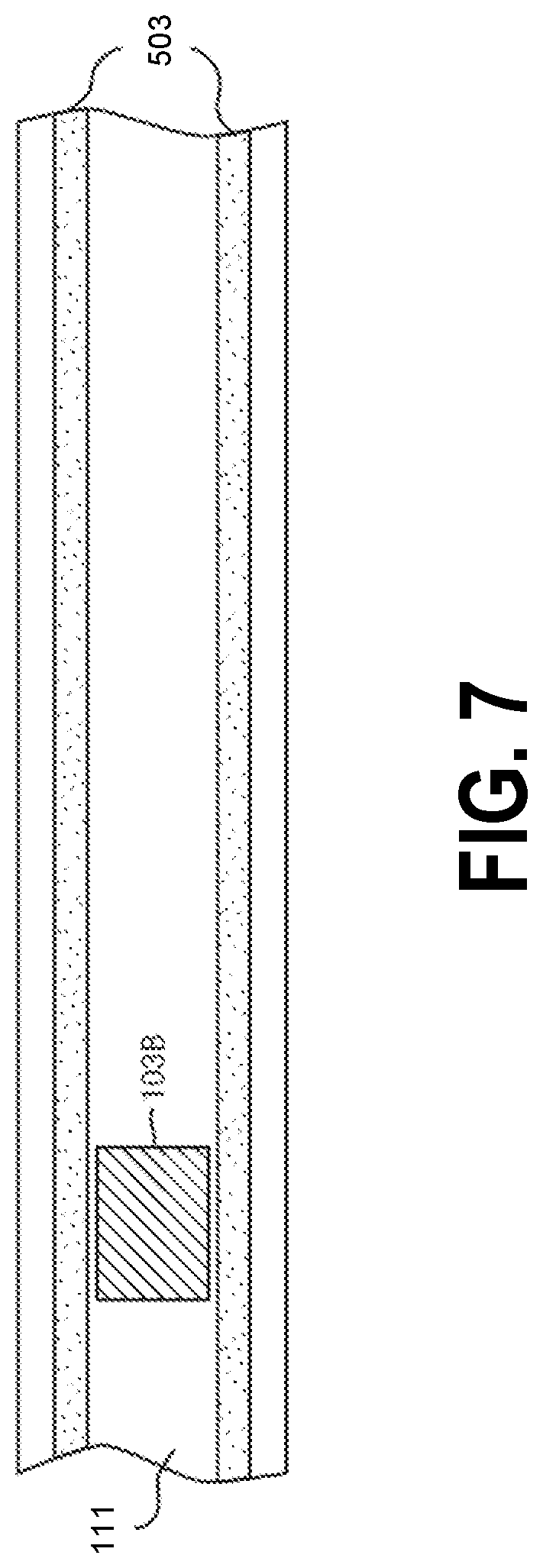
[0017] FIG. 7 shows a track piece with a permanent optical marker, according to one example embodiment.
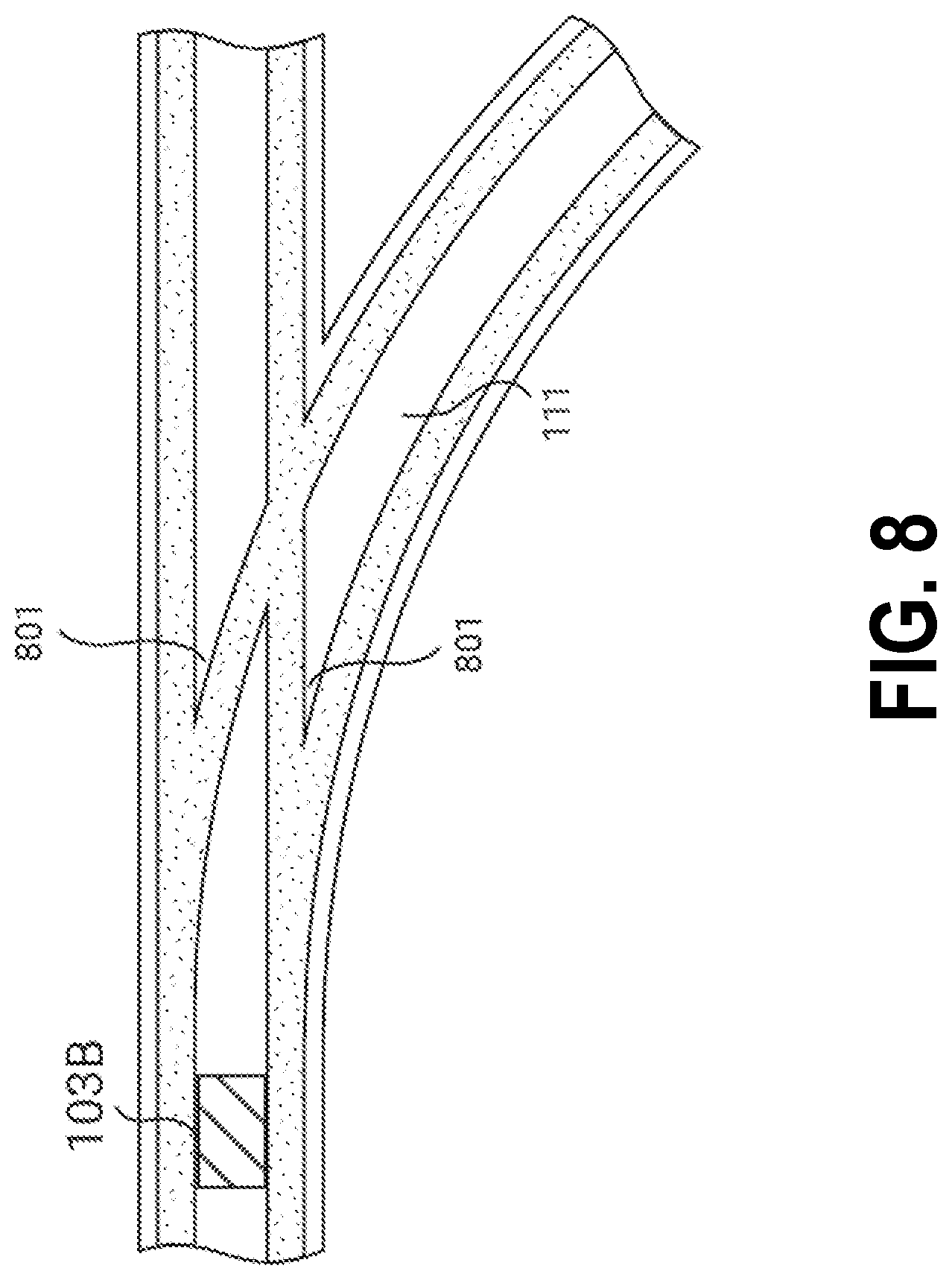
[0018] FIG. 8 shows a junction track piece with a permanent optical marker applied before a junction, according to one example embodiment.
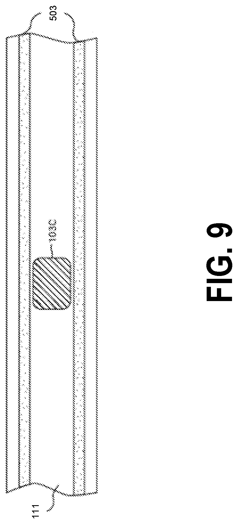
[0019] FIG. 9 shows a track piece with a non-permanent adhesive optical marker, according to one example embodiment.
[0020] FIG. 10 shows a track piece with a magnetic optical marker, according to one example embodiment.
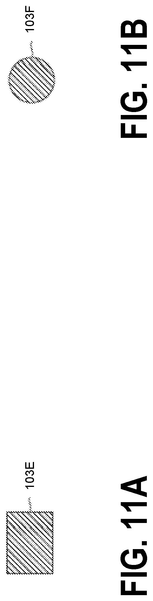
[0021] FIG. 11A shows an optical marker with a rectangular upper surface, according to one example embodiment.
[0022] FIG. 11B shows an optical marker with a circular upper surface, according to one example embodiment.
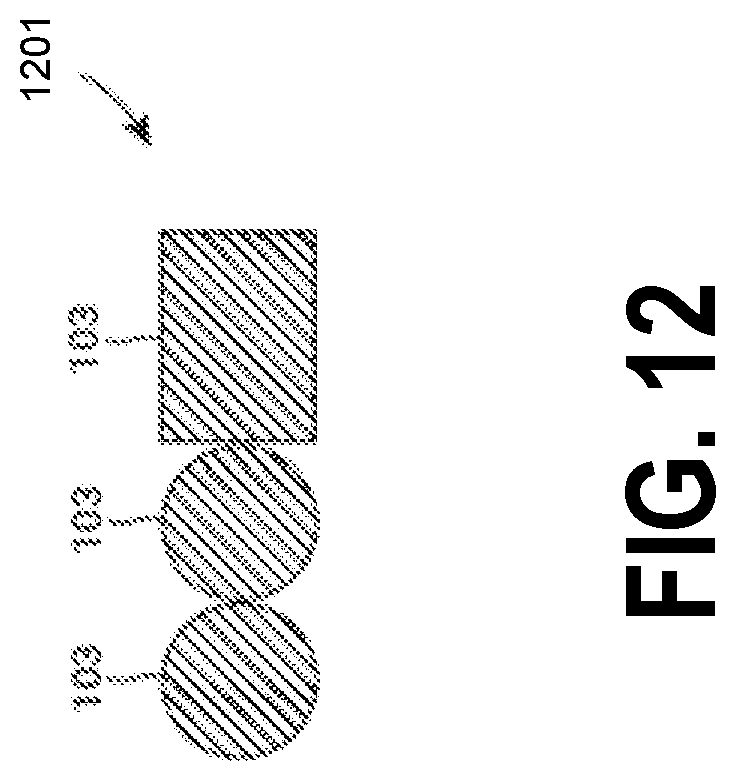
[0023] FIG. 12 shows a combination/sequence of optical markers, according to one example embodiment.
[0024] FIG. 13A shows a cross-section of a single-sided track piece with dual recessed rails, according to one example embodiment.
[0025] FIG. 13B shows a cross-section of a dual-sided track piece with dual recessed rails, according to one example embodiment.
[0026] FIG. 13C shows a cross-section of a single-sided track piece with dual protruding/embossed rails, according to one example embodiment.
[0027] FIG. 13D shows a cross-section of a dual-sided track piece with dual protruding/embossed rails, according to one example embodiment.
[0028] FIG. 13E shows a cross-section of a single-sided track piece with a single recessed rail, according to one example embodiment.
[0029] FIG. 14A shows a cross-section of a dual-recessed rail based dual-sided track piece with dual cut-through marker slots, according to one example embodiment.
[0030] FIG. 14B shows a cross-section of the dual-recessed rail based dual-sided track piece with dual cut-through marker slots with an optical marker, according to one example embodiment.
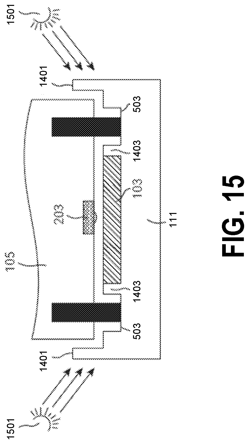
[0031] FIG. 15 shows a track piece with a vehicle in the presence of ambient light sources, according to one example embodiment.
[0032] FIG. 16 shows a track piece with a vehicle and an optical marker along the side of the outer ridge of the track piece, according to one example embodiment.
[0033] FIG. 17A shows an overhead view of track pieces with male and female joints, according to one example embodiment.
[0034] FIG. 17B shows a cross-section of track pieces with male and female joints, according to one example embodiment.
DETAILED DESCRIPTION
[0035] In the following description, numerous specific details are set forth. However, it is understood that embodiments of the invention may be practiced without these specific details. In other instances, well-known circuits, structures and techniques have not been shown in detail in order not to obscure the understanding of this description. Those of ordinary skill in the art, with the included descriptions, will be able to implement appropriate functionality without undue experimentation.
[0036] References in the specification to "one embodiment," "an embodiment," "an example embodiment," etc., indicate that the embodiment described may include a particular feature, structure, or characteristic, but every embodiment may not necessarily include the particular feature, structure, or characteristic. Moreover, such phrases are not necessarily referring to the same embodiment. Further, when a particular feature, structure, or characteristic is described in connection with an embodiment, it is submitted that it is within the knowledge of one skilled in the art to affect such feature, structure, or characteristic in connection with other embodiments whether or not explicitly described.
[0037] In the following description and claims, the terms "coupled" and "connected," along with their derivatives, may be used. It should be understood that these terms are not intended as synonyms for each other. "Coupled" is used to indicate that two or more elements, which may or may not be in direct physical or electrical contact with each other, co-operate or interact with each other. "Connected" is used to indicate the establishment of communication between two or more elements that are coupled with each other or a direct physical connection.
[0038] FIG. 1 shows a track system 100 with optical markers 103, according to one example embodiment. As shown, the track system 100 includes a track 101 and a set of optical markers 103. The track 101 may be comprised or otherwise assembled from one or more interconnected track pieces 111. The track pieces 111 may be in various forms or styles (e.g., straight, curved right, curved left, etc.). As will be described in greater detail below, the optical markers 103 are coupled to various positions along the track 101 such that a vehicle 105 with optical sensing capabilities may detect the optical markers 103 as the vehicle 105 approaches, traverses, passes over, or is otherwise proximate the optical markers 103. The vehicle 105 may traverse the track 101 while powered by one or more motors or while being manually pushed by a user of the track system 100. Upon detecting an optical marker 103, the vehicle 105 may perform an action associated with the detected optical marker 103 or a sequence/combination of two or more optical markers 103. The use of optical markers 103 with the track system 100 may provide additional interactivity with and/or additional control over the vehicle 105. For example, this additional interactivity and control may extend to track navigation, gamified entertainment, and/or educational purposes. Various elements of the track system 100 will be described in greater detail below by way of example.
[0039] As noted above, the track system 100 may include or may be otherwise associated with a vehicle 105 with optical sensing capabilities. FIG. 2 shows a component diagram of a vehicle 105 with optical sensing capabilities, according to one example embodiment. In the example embodiment shown in FIG. 2, the vehicle 105 may be any device that uses an electro-mechanical mechanism 205 and a set of optical sensors 203, which allow the vehicle 105 to detect the optical markers 103 positioned along the track 101. However, as noted above, in some embodiments, the vehicle 105 may not include an electro-mechanical mechanism 205, but instead is propelled manually by a user of the track system 100 and/or the vehicle 105 (e.g., a user manually pushes, pulls, or otherwise moves the vehicle 105 along the track 101) or may be propelled by a force external to the vehicle 105, the track 101, and a user (e.g., a device separate from the vehicle 105, a user, and the track 101 that pushes, pulls, or otherwise moves the vehicle 105 along the track 101). The electro-mechanical mechanism 205 may include one or more motors 207 that are coupled to wheels of the vehicle 105. The motors 207 cause the wheels to turn and propel the vehicle 105 around/along the track 101. As will be described in greater detail below, the wheels of the vehicle 105 may be complementary to a set of rails of the track 101 (in particular, complementary to rails of track pieces 111 of the track 101). The motors 207 may be controlled by one or more motor controllers (not shown), which control the speed of rotation of the motors 207 (e.g., rounds per minute). As used herein, the term engine may be used synonymously with the term motor and shall designate a machine that converts one form of energy into mechanical energy. For example, the motors 207 may be electrical motors/engines that convert electricity stored in a battery of the vehicle 105 into mechanical energy. The motors 207 power the movement of the vehicle 105 on/along the track 101 in a pre-programmed, remotely controlled, or autonomous fashion. As used herein, autonomous movement is an operating mode that does not involve human interaction or involves minimal human interaction. For example, a human user may turn on the vehicle 105 (e.g., toggle a power switch of the vehicle 105) and place the vehicle 105 on the track 101. After being placed on the track 101, the vehicle 105 may traverse various portions/areas of the track 101 according to an autonomous algorithm (e.g., the vehicle 105 may utilize inputs from the optical sensors 203 (e.g., sensor data) to determine a route along the track 101 and/or a set of actions to perform while moving along the track 101).
[0040] As shown in FIG. 2, the vehicle 105 may include a processor 201 and a memory unit 209. The processor 201 and the memory unit 209 are used here to represent a suitable combination of programmable data processing and storage components that perform the operations needed to implement the various functions and operations of the vehicle 105. For example, as will be described in greater detail below, the memory unit 209 may include an optical sensing unit 211 for autonomously controlling the vehicle 105 to traverse the track 101 according to optical markers 103 positioned along the track 101. The processor 201 may be a special purpose processor such as an application-specific integrated circuit (ASIC), a general purpose microprocessor or a microcontroller, a field-programmable gate array (FPGA), a digital signal controller, or a set of hardware logic structures (e.g., filters, arithmetic logic units, and dedicated state machines), while the memory unit 209 may refer to any suitable combination of microelectronic, non-volatile random access memory and flash memory circuits, which may be internal or external to the processor 201. In certain embodiments, an operating system may be stored in the memory unit 209 in addition to the optical sensing unit 211. Application programs specific to the various functions of the vehicle 105 may be stored in the memory unit 209, which are to be run or executed by the processor 201 to perform the various functions and operations of the vehicle 105. For example, as noted above, an optical sensing unit 211 may be stored in the memory unit 209 and may be run/executed by the processor 201. The optical sensing unit 211 may perform various functions/operations associated with the detection and classification of the optical markers 103 and triggering notifications to the processor 201 resulting in various actions performed by the vehicle 105, as described in greater detail below.
[0041] As noted above, the vehicle 105 includes a set of optical sensors 203 for detecting optical markers 103, including characteristics of the optical markers 103 (e.g., color, shape, shading, size, etc.). For example, in some embodiments, the set of optical sensors 203 may include one or more photoresistors and/or phototransistors. These photoresistor/phototransistor based optical sensors 203 may be particularly utilized for detecting and/or identifying colors of optical markers 103. For example, these photoresistor/phototransistor based optical sensors 203 may detect the intensity of reflected light from the surface of optical markers 103. As used herein, an optical marker 103 includes an upper surface, which includes an associated shape and/or color, and a lower connecting element for coupling with a portion of the track 101 (in particular, coupling with complementary elements of track pieces 111) according to the preferences of a user. An optical marker 103 with a lighter surface color reflects a higher intensity of light compared to another optical marker 103 with a darker surface color. Accordingly, the intensity level returned by an optical sensor 203 may be used for determining the surface color of an optical marker 103. In some embodiments, an optical sensor 203 may include an internally or externally integrated light source (e.g., a light emitting diode (LED)) to provide a local illumination of the upper surface of an optical marker 103 even in dark ambient light conditions, such that the optical sensor 203 is able to detect reflected light from the upper surface of an optical marker 103. In some embodiments, one or more photoresistor/phototransistor based optical sensors 203 may be an infrared (IR) photoresistor or phototransistor capable of detecting the intensity of infrared reflected light from an optical marker 103 illuminated by an IR LED integrated in or otherwise associated with an optical sensor 203.
[0042] Based on reflected light data collected by a set of optical sensors 203 (sometimes referred to as sensor data or raw sensor data) and transmitted to the main processor 201, the optical sensing unit 211 may classify the surface color of an optical marker 103. For example, using a thresholding algorithm the optical sensing unit 211 may determine the surface color of an optical marker 103 (e.g., an intensity level between a first set of threshold values corresponds to a first color, an intensity level between a second set of threshold values corresponds to a second color, etc.). In some embodiments, the optical sensing unit 211 may include data processing and calibration routines to improve the robustness of color classification under different ambient lighting conditions.
[0043] Although described as photoresistor/phototransistor based optical sensors 203, in some embodiments, the set of optical sensors 203 included in the vehicle 105 may include one or more digital color sensors, which includes multiple photodiode segments for red, green, blue, and clear channels and has the computational capacity to simultaneously integrate and output color sensor data to the processor 201 using a communication interface (e.g., a two-wire Inter-Integrated Circuit (I2C) serial bus). These digital color based optical sensors 203 enable the representation of the optical markers 103 using a finite number of different colors (e.g., red, green, blue, etc.). The number of reliably detectable colors by a vehicle 105 is dependent on the performance characteristics of the set of optical sensors 203 and the processor 201, as well as the algorithmic sophistication of the optical sensing unit 211. FIG. 3A shows an example of a top surface of single color optical marker 103 according to one example embodiment. Single color optical markers 103 may be represented using a single shape (e.g., a square, circle, etc.) of a single color (e.g., red, green, etc.). The example optical sensors 203 thus far described may be used for identifying/classifying the color of a single color optical marker 103.
[0044] In some embodiments, the set of optical sensors 203 included in the vehicle 105 may include one or more low resolution digital cameras, which are each capable of capturing two-dimensional (2D) images in a form of a 2D matrix of data of light intensities in either grayscale (in the visible or infrared spectrum) or red-green-blue (RGB) color forms. Such low resolution digital camera based optical sensors 203 enable optical markers 103 to be represented in 2D patterns (e.g., a pattern that includes a set of shapes that each are represented with a color (e.g., black or white)). An example of such a 2D optical marker 103 is shown in FIG. 3B. The complexity and detailed variance of such 2D patterns used as optical markers 103 is dependent on the performance characteristics of the low resolution digital camera based optical sensors 203, the processor 201, and the algorithmic sophistication of the optical sensing unit 211.
[0045] Although not shown in FIG. 2, in some embodiments, the vehicle 105 may also include components to provide audio-visual feedback to a user of the track system 100 and/or a vehicle 105. For example, the vehicle 105 may include a speaker for playing back sounds stored in the memory unit 209 in conjunction with various actions of the vehicle 105 (e.g., output a sound upon detecting an optical marker 103 or upon identifying a particular color of an optical marker 103). In another example, the vehicle 105 may include single or multi-color LEDs to provide visual feedback to the user of the track system 100 and/or the vehicle 105, and/or perform light animations upon detecting an optical marker 103 or upon identifying a particular color of an optical marker 103.
[0046] Additionally, although not shown in FIG. 2, the vehicle 105 may include an electro-magnet component to couple the vehicle 105 to other devices. For example, an electro-magnet component may be placed on the front and/or rear of the vehicle 105 to couple the vehicle 105 with other associated devices that are capable of traversing the track 101 (e.g., other devices that include wheels that complement with corresponding rails (either raised/protruding or recessed) of the track 101). For example, when the track system 100 is a toy train system, such associated devices may be wagons or cars with permanent magnet couplers to which the vehicle 105 can be coupled using the electro-magnet component. In some embodiments, the described electro-magnet component of the vehicle 105 may be an electro-permanent magnet. The electro-magnet component described herein may be capable of generating a magnetic field strong enough to counter the attracting field force generated by the permanent or electro-permanent magnet of an associated device to decouple the vehicle 105 from the associated device. In some embodiments, the electro-magnet component of the vehicle 105 may be controlled by the user using a wirelessly connected controller running a companion application (e.g., a telephone, a tablet, or another similar computing platform). In other embodiments, the electro-magnet component of the vehicle 105 may be controlled using optical markers 103 detected by the vehicle 105 on the track 101. For example, in response to detecting a particular optical marker 103 (e.g., a green optical marker 103) or a particular sequence of optical markers 103 (e.g., a white optical marker 103 followed by a green optical marker 103), the electro-magnet component may generate a magnetic field strong enough to counter the attracting field force generated by a magnet of an associated device to decouple the vehicle 105 from the associated device.
[0047] Turning now to FIG. 4, a method 400 will be described for operating the vehicle 105 on the track system 100, according to one example embodiment. Each operation of the method 400 may be performed by one or more of the vehicle 105, the track system 100, and a user. For example, as noted above, the track 101 may include one or more optical markers 103 coupled to corresponding track pieces 111 and the vehicle 105 may include an optical sensing unit 211 that (1) detects optical markers 103, including characteristics of optical markers 103 and (2) causes the vehicle 105 to perform actions in response to detection/classification of optical markers 103. In other embodiments, the operations/functions associated with the optical sensing unit 211 may be performed by devices external to the vehicle 105. For example, a wirelessly connected device running a companion application that processes data captured in real-time by the optical sensors 203 may perform one or more operations (or partial operations) of the method 400. As used herein, the term `real-time` refers to a timeframe that is required to capture raw sensor data by an optical sensor 203 and transmit the raw sensor data to the external processing device such that the performance and functional requirements of the vehicle 105 are met.
[0048] Although shown and described in a particular order, in some embodiments the operations of the method 400 may be performed in a different order. For example, in some embodiments, two or more operations of the method 400 may be performed concurrently or in partially overlapping time periods.
[0049] Although the method 400 is described in relation to a single vehicle 105 navigating the track 101, in other embodiments, the method 400 may be simultaneously performed (or at least performed in partially overlapping time periods) in relation to two or more separate vehicles 105 that are traversing the track 101.
[0050] As shown in FIG. 4, the method 400 may commence at operation 401 with assembly of the track 101 using a set of track pieces 111. The track pieces 111 may include a variety of shapes that vary movement of the vehicle 105. For example, the set of track pieces 111 may include straight track pieces 111, curved track pieces 111, junction track pieces 111, etc. Additionally, each track piece 111 may include interconnecting joints allowing a user to snap individual track pieces 111 together to form a track 101 of a desired shape and complexity at operation 401. FIG. 1 shows an example track 101 that may be generated at operation 401 using a set of track pieces 111.
[0051] After assembling the track 101 at operation 401, one or more optical markers 103 are placed by a user onto desired locations/positions of the track 101 at operation 403. In some embodiments, individual optical markers 103 may be placed on the track 101, while in other embodiments sequences of optical markers 103 may be placed on the track 101 (e.g., a group of optical markers 103 that are placed directly adjacent to each other on the track 101).
[0052] At operation 405, the vehicle 105 is placed on the track 101 such that the vehicle 105 can begin traversing the track 101 to detect optical markers 103. In particular, as described above, the vehicle 105 may include optical sensing abilities that allow the vehicle to detect optical markers 103 as the vehicle traverses the track 101.
[0053] At operation 407, the vehicle 105 continuously gathers and/or generates sensor data while traversing the track 101. For example, using the electro-mechanical mechanism 205, the vehicle 105 may traverse the track 101 to move over or otherwise proximate to a number of optical markers 103. During this movement, the set of optical sensors 203 of the vehicle 105 may generate sensor data corresponding to optical markers 103 or other areas of the track 101.
[0054] At operation 409, the generated sensor data is continuously processed by the optical sensing unit 211 to determine when an optical marker 103 has been detected. When the optical sensing unit 211 determines at operation 409 that the sensor data does not correspond to an optical marker 103 (i.e., the optical sensing unit 211 determines that an optical marker 103 was not detected at operation 409), the method 400 may return to operation 407 to continue to generate sensor data while the vehicle 105 traverses the track 101. In contrast, when the optical sensing unit 211 determines at operation 409 that the sensor data corresponds to an optical marker 103 (i.e., the optical sensing unit 211 determines that an optical marker 103 was detected at operation 409), the method 400 may move to operation 411.
[0055] At operation 411, the vehicle 105 may perform a set of actions associated with the detected optical marker 103. In one embodiment, such actions may be stored in the memory unit 209 in a form of application programs or functions. In other embodiments, the application programs or functions representing various actions may be stored externally. For example, application programs or functions representing various actions may be stored within a device connected wirelessly to the vehicle 105 via an application programming interface (API). Each of the actions may be linked/mapped or otherwise associated with a set of optical markers 103 and/or a set of sequences of optical markers 103. Examples of various actions triggered using the optical markers 103 (i.e., upon detection of a particular optical marker 103 at operation 409) and performed by the vehicle 105 may include 1) the vehicle 105 reversing direction (i.e., the vehicle 105 moving in the opposite direction along the track 101); 2) the vehicle 105 changing speed (e.g., the vehicle 105 accelerating to increase speed along the track 101 or decelerating to decrease speed along the track 101); 3) the vehicle 105 pausing movement along the track 101; 4) the vehicle 105 performing a special maneuver (e.g., the vehicle 105 stopping and performing a shaking maneuver by moving the vehicle 105 forwards and backwards by a prescribed distance (e.g., one centimeter) three times while playing back a sound effect); 5) the vehicle 105 changing an LED color or displaying an animation via a set of LEDs or another display component; 6) the vehicle 105 playing a sound; and 7) the vehicle 105 activating or deactivating an actuator or an electro-magnet component (e.g., activating or deactivating an electro-magnet component to decouple an associated device from the vehicle 105).
[0056] Following operation 411, the method 400 may return to operation 407 to continue generating sensor data while the vehicle 105 is moving across or otherwise traversing the track 101. The method 400 may therefore continue indefinitely until an end condition has been reached (e.g., the end of the track 101 is reached or the vehicle 105 is stopped by a user).
[0057] Depending on the mechanical design of the vehicle 105 and its applications, the track 101 may be made from different materials, use different track pieces 111 and corresponding rail types to guide the vehicle 105, and utilize different track piece assembly methods. In embodiments in which the track system 100 is miniaturized (e.g., when the track system 100 is a toy train system), the track 101 may be made from injection molded plastic or wooden track pieces 111. In embodiments that require a higher degree of reliability and longevity in comparison to toy applications (e.g., when the track system 100 is used for security and/or transportation/delivery applications), the track pieces 111 that form the track 101 may be made using metals (e.g., aluminum or stainless steel) or metal alloys.
[0058] In some embodiments, the track system 100 may contain a track 101 with elements designed for the placement of removable optical markers 103. Namely, elements may be integrated into the track pieces 111 for removably coupling optical markers 103 to the track 101. For example, FIG. 5A shows pairs of elongated slots 505A directly adjacent to track rails 503 of a track piece 111. In particular, each pair of elongated slots 503 are placed along inside edges of corresponding rails 503 of a track piece 111. In comparison, FIG. 5B shows round slots 505B located centrally between the rails 503 of a track piece 111. In some embodiments, such slots 505A and 505B may be formed using a combination of one or more of extrusion, recessed, or cut-through shapes. As shown in FIG. 5C, the slots 505A provide a mechanical interface for coupling replaceable optical markers 103A onto the track pieces 111 in a manner that cause these replaceable optical markers 103A to stay in the desired position along the track 101 without easily shifting around or obstructing the movement of the vehicle 105. However, the replaceable optical markers 103A may be removed from the track 101/track pieces 111 without tools (e.g., the replaceable optical markers 103A include protrusions that fit within the slots 505A to ensure minimal or no lateral movement of the replaceable optical markers 103A along the track 101/track pieces 111, but allows for movement of the replaceable optical markers 103A along an axis perpendicular to the track 101/track pieces 111).
[0059] FIG. 6 shows example cross-section views of a replaceable optical marker 103A and a track piece 111, where both have complementary coupling features that allow easy replacement and or movement of the optical markers 103A to different positions along the track piece 111 (e.g., the optical marker 103A has a first set of marker coupling components and the track piece 111 has a second set of marker coupling components that are complementary to the first set of marker coupling components to couple the optical marker 103A to the track piece 111). In particular, the optical marker 103A includes recesses 601A that fit within and are complementary to protrusions 603A of the track piece 111. The optical marker 103A may also include protrusions 601B that fit within and are complementary to recesses 603B of the track piece 111. In some embodiments, the optical marker 103A may include protrusion 601C that fits within or is otherwise complementary with the recess 603C of the track piece 111. For example, the recess 603C may be the slot 505B, which prevents movement of the optical marker 103A in a direction parallel to the rails 503. This coupling between the optical marker 103A and the track piece 111 is helpful in the assembly of continuous optical marker 103 sequences, which are comprised of two or more directly adjacent optical markers 103. As described above, through the use of one of more of the recesses 601A, 603B, and 603C and the protrusions 603A, 601B, and 601C, the optical marker 103A may be coupled to the track 101 (in particular, coupled to track pieces 111 of the track 101).
[0060] In another embodiment shown in FIG. 7, a permanent optical marker 103B may be added permanently to the track piece 111 using paint, adhesives, and/or another permanent application process. Permanent optical markers 103B enable consistently repeatable actions in certain positions/areas of the track 101. For example, as shown in FIG. 8, a permanent optical marker 103B may be coupled to the track piece 111 in an area of the track piece 111 preceding a track junction 801, where the rails 503 of the track split from one pair of rails 503 into two pairs of rails 503. In this example, the permanent optical marker 103B may notify the vehicle 105 of such a track junction 801 approaching ahead.
[0061] FIG. 9 shows another embodiment of an optical marker 103C that is implemented using a decal, sticker, or another device with a non-permanent adhesive. In this embodiment, the sticker based optical marker 103C may not be permanently affixed to the track piece 111 such that the optical marker 103C may be moved from one position on the track piece 111 to another position on the track piece 111 without eliminating the adhesive properties of the sticker based optical marker 103C. In this embodiment, optical markers 103 may be coupled to the track 101/track pieces 111 without corresponding/complementary elements of the track 101/track pieces 111.
[0062] FIG. 10 shows yet another example embodiment of an optical marker 103D that is implemented using a magnetic strip 1001 that is coupled to a track piece 111. In this embodiment, one or both of the magnetic strip 1001 and the magnetic optical marker 103D produce a magnetic field. In cases where only one of the magnetic strip 1001 and the magnetic optical marker 103D produce a magnetic field (i.e., only one of the magnetic strip 1001 and the magnetic optical marker 103D is or includes a magnet), the non-magnetic field producing element (i.e., the magnetic strip 1001 or the magnetic optical marker 103D) includes a metal that is attracted to magnetic fields.
[0063] As noted above, in some embodiments, optical markers 103 may be of different shapes and sizes. For example, as shown in FIGS. 11A and 11B, the optical marker 103E is rectangular while the optical marker 103F is circular. In particular, an upper surface of the optical marker 103E is rectangular while the upper surface of the optical marker 103F is circular. Although shown as rectangles and circles, optical markers 103 may be of any shape (e.g., hexagon, octagon, triangle, etc.) and are of sufficient size to allow detection/classification via sensor data generated by the optical sensors 103 while the corresponding vehicle is moving along a track 101.
[0064] In some embodiments, a combination/sequence 1201 of optical markers 103 may be assembled to from a continuous sequence of two or more individual optical markers 103, as shown in FIG. 12. A multi-piece combination/sequence 1201 of optical markers 103 may represent a trigger for an action of the vehicle 105 in a similar fashion as an individual optical marker 103 may serve as a trigger. Each optical marker 103 in a combination/sequence of optical markers 103 (e.g., the multi-piece combination/sequence 1201 of optical markers 103) may be represented by the same physical shapes or may include different shapes. For example, as shown in FIG. 12, the multi-piece combination/sequence 1201 of optical markers 103 includes both circle and square optical markers 103 that are positioned in a continuous manner such that a vehicle 105 is able to detect/classify the optical markers 103 as the vehicle 105 passes over or adjacent to each optical marker 103.
[0065] Depending on application needs and performance requirements, the track 101 may utilize various rail types. FIG. 13A depicts a cross-section of a track piece 111A with dual rails 503A. As shown, the rails 503A are recessed grooves along one side of the track piece 111A. In this embodiment, the vehicle 105 is designed with complementary wheels. Namely, the wheels of the vehicle 105 are designed to fit within the recessed grooves of the rails 503A for proper operation and compatibility. Although the rails 503A are shown along a single side of the track piece 111A, in some embodiments, rails 503 may be placed on both sides of a single track piece 111. For example, FIG. 13B shows a dual-sided track piece 111B with two sets of grooved rails 503A, which are on opposing sides of the track piece 111B, according to another embodiment.
[0066] Although shown with recessed rails 503, in some embodiments, the rails 503 may be protruding/embossed on track pieces 111. For example, FIGS. 13C and 13D show single and dual-sided track pieces 111C and 101D, respectively, with protruding/embossed rails 503B. Further, although shown with pairs of rails 503, in some embodiments, a track piece 111 may include a single rail 503. For example, FIG. 13E shows a track piece 111E with a single recessed rail 503A (e.g., a mono-rail). In this example embodiment, the wheels of a vehicle 105 fit entirely within the recessed rail 503A to travel along the track piece 111E of a track 101. Although shown as a single recessed rail 503A, a single raised rail may also be used.
[0067] FIG. 14A shows a cross-section, according to one embodiment, of a dual-recessed rail 503A based dual-sided track piece 111B with dual cut-through marker slots 505A. In some embodiments, the track piece 111B may be made from a plastic material such as acrylonitrile butadiene styrene (ABS) using an injection molded manufacturing process. Such a version of a track piece 111B may be used in track systems 100 for toy train applications which involve custom track 101 assembly by the user. This configuration benefits from the versatility provided by a dual-sided track piece 111B design. In some embodiments, the outer ridges 1401 and the inner ridges 1403 forming the grooved rails 503A may have different heights. For example, the outer ridges 1401 may be made taller in comparison to the inner ridges 1403, to reduce the chance of derailing when the vehicle 105 traverses a track 101 at higher speeds. FIG. 14B shows the optical marker 103A with a first set of marker coupling components and the track piece 111B with a second set of marker coupling components that are complementary to the first set of marker coupling components to couple the optical marker 103A to the track piece 111B. The first set of marker coupling components are on a bottom surface of the optical marker 103A that is opposite a top surface of the optical marker 103A. The top surface of the optical marker 103A may be formed of any shape and may include/display a set of shapes and colors that are detectable/identifiable by the vehicle 105. As shown in FIG. 14B, the first set of coupling components includes a set of protruding elements. The set of protruding elements may include (1) a first protruding element located adjacent a first outside edge of a bottom surface of the optical marker 103A, (2) a first protruding element located adjacent a second outside edge of the bottom surface of the optical marker 103A, which is opposite the first outside edge, and (3) third and fourth protruding elements located between the first protruding element and the second protruding element on the bottom surface such that the first protruding element, the second protruding element, the third protruding element, and the fourth protruding element form a symmetric structure about an axis of the bottom surface.
[0068] In one embodiment shown in FIG. 14B, the height of the inner ridges 1403 may be chosen such that when combined with a replaceable optical marker 103A that is placed on top of such an inner ridge 1403, the collective height of the inner ridge 1403 and the optical marker 103A resting on the inner ridge 1403 is the same as the height of the outer ridge 1401. Alternatively, if there is a height difference between the outer ridge 1401 and the combined height of the inner ridge 1403 and the portion of the optical marker 103A resting on the inner ridge 1403, such a height difference is less than the minimum clearance requirement of the vehicle 105. In other embodiments, the outer ridges 1401 and the inner ridges 1403 may have the same height. In embodiments where the width of the track 101 is less than or equal to the width of the vehicle 105, the heights of the outer ridges 1401 and the inner ridges 1403 may be limited by the bottom clearance of the vehicle 105 from the track 101. The vehicle 105 with optical sensors 203 may have a clearance that is dependent on the width and length of the bottom of the vehicle 105. In order to reduce the impact of ambient light on performance of the optical sensors 203, the optical sensors 203 may be positioned away from the outer edges of the vehicle 105 such that these optical sensors 203 are within the shadow of the vehicle 105. On the other hand, the minimum clearance of the vehicle 105 is large enough to not be obstructed by the joints of the track 101 and/or slopes of track pieces 111 that are ramps. For example, in vehicles 105 that have widths of approximately 40 millimeters (mm), the clearance between the bottom of the vehicle 105 and the track 105 may be set to be less than 5 mm.
[0069] In another example embodiment, the width of the track piece 111B may be sufficiently wider than the width of the vehicle 105 such that the outer ridges 1401 always stay around the exterior of the vehicle 105 and would not be limited by the clearance height of the vehicle 105.
[0070] The reliability of the optical marker 103 detection by the vehicle 105 traversing track systems 100 may be adversely affected by the presence of a strong ambient light. FIG. 15 shows a track piece 111 with a vehicle 105 in the presence of ambient light sources 1501. In certain configurations of the track piece 111 orientation in relation to the ambient light sources 1501, such ambient light sources 1501 may be generating light that is reflected by the track piece 111 and an optical marker 103 in a manner that interferes with the ability of the sensor(s) 203 to reliably detect the optical marker 103, including the color of the optical marker 103. To reduce the effect of the ambient light sources 1501 on the detection of the optical marker 103, in one embodiment, the outer ridges 1401 may be included in the track piece 111 to block light from ambient light sources 1501 that may interfere with the detection of the optical markers 103.
[0071] FIG. 16 shows another embodiment of a track piece 111 with a vehicle 105. However, in contrast to several other embodiments described herein, instead of using optical markers 103 that are placed within the recesses of rails 503 of a track piece 111, the optical marker 103 shown in FIG. 16 is placed along the side of the outer ridge 1401 of the track piece 111. The vehicle 105 operating on such a track system 100 is designed such that an optical sensor 203 is positioned to detect the side-placed optical marker 103. Such a side-placed optical marker 103 may function in a similar fashion as other embodiments described herein, including those embodiments in which the optical markers 103 are placed on the upwards facing surface of track pieces 111 (i.e., the side of the outer ridge 1401). Track systems 100 that incorporate side-placed optical markers 103 may provide advantages in comparison to other track systems 100 in terms of resistance to ambient light sources, since the placement of the optical markers 103 on the outer ridge 1401 provides a shield for optical sensors 203 from direct exposure to ambient light.
[0072] As discussed above, in some embodiments, tracks 101 are assembled from individual track pieces 111. For example, toy train track systems allow the user to build custom tracks 101 from various different types of track pieces 111 (e.g., straights track pieces 111, curved track pieces 111, and split/junction track pieces 111). Split/junction track pieces 111 form a junction to either divide a single set of rails into multiple sets of rails or to merge multiples sets of rails into a single set of rails as shown in the example of FIG. 8. To streamline the assembly of tracks 101, various joint designs are used to securely link track pieces 111 together. In one embodiment, shown in FIGS. 17A and 17B, a set of plastic injection molded track pieces 111 may contain an extruded male/protruding joint 1701 and a complementary female/recessed joint 1703, which each have circular shapes that interlock when a user snaps the joints 1701 and 1703 together. Although shown as the joints 1701 and 1703 having a circular shape, in other embodiments, the joints 1701 and 1703 may have different shapes (e.g., squares, rectangles, octagons, etc.). For example, in the case of a circular connector, the maximum width of the male joint 1701 (defined by the diameter of a circle/rounded area of the male joint 1701) is larger than the width of the opening at the front of the female joint 1703 to avoid the track pieces 111 from coming apart due to external forces parallel to the track pieces 111. The tightness of the fit between the male joint 1701 and female joint 1703 may be chosen such that it is easy for a user to manually link and unlink corresponding track pieces 111 with minimal force. Such a force should not exceed the limits that may cause mechanical damage to the joints 1701 and 1703 based on the material type used to make the track 101, yet the fit between the joints 1701 and 1703 is tight enough to maintain the rigidity of the assembled track pieces 111 and avoid an inadvertent disassembly of the track pieces 111 during normal operation of the vehicle 105 on the track 101. When the joints 1701 and 1703 are snapped together, the corresponding track pieces 111 will not come apart without an external force directed to pull the track pieces 111 apart. In one embodiment, the female joint 1703 may also contain dual slits 1709 on either side of the circular opening of the joint 1703. These slits 1709 provide flexibility for the female joint 1703. This lower flexibility results in a reduced force and a reduced potential for mechanical damage during the interlocking process between the female joint 1703 of a track piece 111 and a male joint 1701 of another track piece 111.
[0073] In some embodiments, the male joint 1701 may include a lip 1705 along an outer edge, while the opening of the female joint 1703 may have alternating knobs/tabs 1707 placed along a top edge and a bottom edge of the opening of the female joint 1703 (e.g., the knobs/tabs 1707A are placed on a top edge of the opening of the female joint 1703 and the knobs/tabs 1707B are placed on a bottom edge of the opening of the female joint 1703). Collectively, the lip 1705, the knobs/tabs 1707A along a top edge, and the knobs/tabs 1707B along a bottom edge provide an additional locking mechanism when the track pieces 111 are snapped together along the joints 1701 and 1703. Such a mechanism provides improved vertical alignment between track pieces 111 while maintaining a surface of a track 101 formed by the track pieces 111 continuously smooth and flat even if the track 101 is assembled on an uneven surface (e.g., assembled on a carpet). The alternating placement of the knobs/tabs 1707A and 1707B allow the core and the cavity of a plastic injection mold to form these elements in plastic and come apart without catching when ejecting from the mold. The quantity and size of the knobs/tabs 1707A and 1707B can be varied in terms of the lengths, heights, and extension from the opening of the female joint 1703 as long as the knobs/tabs 1707A and the knobs/tabs 1707B remain non-overlapping from a top-down/overhead perspective and the knobs/tabs 1707A/1707B can form a coupling joint with the lip 1705. In particular, a set of knobs/tabs 1707A are positioned along a top edge of the recessed female joint 1703 and a set of knobs/tabs 1707B are positioned along a bottom edge of the recessed female joint 1703 such that knobs/tabs 1707A along the top edge are unaligned with knobs/tabs 1707B along the bottom edge.
[0074] The shape of the knobs/tabs 1707A/1707B can be varied, including, for example, rounded and rectangular shapes. The knobs/tabs 1707A/1707B are complementary to the shape of the lip 1705 to form a connection/joint. The tightness of such a connection/joint may be affected by the shape and the size of the knobs/tabs 1707A/1707B and the lip 1705 and is optimized to make the connection/joint assembly easy for the user, maintain the mechanical integrity of the knobs/tabs 1707A/1707B and the lip 1705 over the expected lifetime of the track 101, and provide a sufficient joint strength to maintain the track 101 flat.
[0075] As shown above, several embodiments for a track system for a robotic vehicle are described herein. Similar or identical example embodiments are provided below. Example 1 provides an exemplary embodiment of a track system for a robotic vehicle, the track system comprising: a set of track pieces that each include a set of track coupling components to couple the track pieces in the set of track pieces together to form a track for the robotic vehicle to traverse; and a set of optical markers that each include a first set of marker coupling components, wherein the set of track pieces include a second set of marker coupling components that are complementary to the first set of marker coupling components to couple the set of optical markers to the set of track pieces.
[0076] Example 2 includes the substance of the exemplary track system of Example 1, wherein each optical marker in the set of optical markers includes a top surface that includes one or more of (1) a surface color and (2) a set of two-dimensional shapes on the top surface.
[0077] Example 3 includes the substance of the exemplary track system of Example 2, wherein the top surface of each optical marker is formed from a shape selected from a set of shapes.
[0078] Example 4 includes the substance of the exemplary track system of Example 2, wherein the first set of marker coupling components are on a bottom surface that is opposite the top surface.
[0079] Example 5 includes the substance of the exemplary track system of Example 4, wherein the first set of marker coupling components includes a set of protruding elements.
[0080] Example 6 includes the substance of the exemplary track system of Example 5, wherein (1) a first protruding element in the set of protruding elements is located adjacent a first outside edge of the bottom surface of the optical marker, (2) a first protruding element in the set of protruding elements is located adjacent a second outside edge of the bottom surface of the optical marker, which is opposite the first outside edge, and (3) third and fourth protruding elements in the set of protruding elements are located between the first protruding element and the second protruding element on the bottom surface such that the first protruding element, the second protruding element, the third protruding element, and the fourth protruding element form a symmetric structure about an axis of the bottom surface.
[0081] Example 7 includes the substance of the exemplary track system of Example 1, wherein the second set of marker coupling components includes a first set of slots through track pieces in the set of track pieces.
[0082] Example 8 includes the substance of the exemplary track system of Example 7, wherein each track piece in the set of track pieces includes a set of grooves or a set of rails for receiving wheels of the robotic vehicle.
[0083] Example 9 includes the substance of the exemplary track system of Example 8, wherein the set of grooves is a mono-groove system for receiving wheels of the robotic vehicle.
[0084] Example 10 includes the substance of the exemplary track system of Example 8, wherein the set of rails is a mono-rail system for receiving wheels of the robotic vehicle.
[0085] Example 11 includes the substance of the exemplary track system of Example 8, wherein the set of grooves is a dual-groove system for receiving wheels of the robotic vehicle.
[0086] Example 12 includes the substance of the exemplary track system of Example 8, wherein the set of rails is a dual-rail system for receiving wheels of the robotic vehicle.
[0087] Example 13 includes the substance of the exemplary track system of Example 11, wherein the first set of slots are placed between each groove in the set of grooves.
[0088] Example 14 includes the substance of the exemplary track system of Example 13, wherein a first slot in the first set of slots is adjacent a first groove in the set of grooves and a second slot in the first set of slots is adjacent a second groove in the set of grooves.
[0089] Example 15 includes the substance of the exemplary track system of Example 14, wherein the second set of marker coupling components includes a second set of slots through the track piece.
[0090] Example 16 provides an exemplary embodiment of a track piece for use in assembling a track for a robotic vehicle, the track piece comprising: one or more male elements that each form a protruding joint, wherein each male element in the one or more male elements includes a lip along an outer edge of a corresponding protruding joint; and one or more female elements that each form a recessed joint and are complementary with the protruding joints, wherein each female element in the one or more female elements includes a set of tabs along a corresponding recessed joint, and wherein the set of tabs are placed in an alternating sequence along a top edge and a bottom edge of the recessed joint such that tabs along the top edge are unaligned with tabs along the bottom edge.
[0091] Example 17 includes the substance of the exemplary track piece of Example 16, further comprising: a set of slits surrounding recessed joints of the one or more female elements.
[0092] Example 18 includes the substance of the exemplary track piece of Example 16, further comprising: a set of grooves or a set of rails for receiving wheels of the robotic vehicle.
[0093] Example 19 includes the substance of the exemplary track piece of Example 18, wherein the track piece is a junction track piece that splits a first set of grooves into a second set of grooves and a third set of grooves at a junction.
[0094] Example 20 includes the substance of the exemplary track piece of Example 18, wherein the track piece is a junction track piece that splits a first set of rails into a second set of rails and a third set of rails at a junction.
[0095] Some portions of the preceding detailed descriptions have been presented in terms of algorithms and symbolic representations of operations on data bits within a computer memory. These algorithmic descriptions and representations are the ways used by those skilled in the data processing arts to most effectively convey the substance of their work to others skilled in the art. An algorithm is here, and generally, conceived to be a self-consistent sequence of operations leading to a desired result. The operations are those requiring physical manipulations of physical quantities. Usually, though not necessarily, these quantities take the form of electrical or magnetic signals capable of being stored, combined, compared, and otherwise manipulated. It has proven convenient at times, principally for reasons of common usage, to refer to these signals as bits, values, elements, symbols, characters, terms, numbers, or the like.
[0096] It should be borne in mind, however, that all of these and similar terms are to be associated with the appropriate physical quantities and are merely convenient labels applied to these quantities. The present disclosure can refer to the action and processes of a computer system, or similar electronic computing device, that manipulates and transforms data represented as physical (electronic) quantities within the computer system's registers and memories into other data similarly represented as physical quantities within the computer system memories or registers or other such information storage systems.
[0097] The present disclosure also relates to an apparatus for performing the operations herein. This apparatus can be specially constructed for the intended purposes, or it can include a general-purpose computer selectively activated or reconfigured by a computer program stored in the computer. Such a computer program can be stored in a computer readable storage medium, such as, but not limited to, any type of disk including floppy disks, optical disks, CD-ROMs, and magnetic-optical disks, read-only memories (ROMs), random access memories (RAMs), EPROMs, EEPROMs, magnetic or optical cards, or any type of media suitable for storing electronic instructions, each coupled to a computer system bus.
[0098] The algorithms and displays presented herein are not inherently related to any particular computer or other apparatus. Various general-purpose systems can be used with programs in accordance with the teachings herein, or it can prove convenient to construct a more specialized apparatus to perform the method. The structure for a variety of these systems will appear as set forth in the description below. In addition, the present disclosure is not described with reference to any particular programming language. It will be appreciated that a variety of programming languages can be used to implement the teachings of the disclosure as described herein.
[0099] The present disclosure can be provided as a computer program product, or software, that can include a machine-readable medium having stored thereon instructions, which can be used to program a computer system (or other electronic devices) to perform a process according to the present disclosure. A machine-readable medium includes any mechanism for storing information in a form readable by a machine (e.g., a computer). In some embodiments, a machine-readable (e.g., computer-readable) medium includes a machine (e.g., a computer) readable storage medium such as a read only memory ("ROM"), random access memory ("RAM"), magnetic disk storage media, optical storage media, flash memory components, etc.
[0100] In the foregoing specification, embodiments of the disclosure have been described with reference to specific example embodiments thereof. It will be evident that various modifications can be made thereto without departing from the broader spirit and scope of embodiments of the disclosure as set forth in the following claims. The specification and drawings are, accordingly, to be regarded in an illustrative sense rather than a restrictive sense.
* * * * *
D00000
D00001
D00002
D00003
D00004
D00005
D00006
D00007
D00008
D00009
D00010
D00011
D00012
D00013

D00014

D00015
D00016

D00017

XML
uspto.report is an independent third-party trademark research tool that is not affiliated, endorsed, or sponsored by the United States Patent and Trademark Office (USPTO) or any other governmental organization. The information provided by uspto.report is based on publicly available data at the time of writing and is intended for informational purposes only.
While we strive to provide accurate and up-to-date information, we do not guarantee the accuracy, completeness, reliability, or suitability of the information displayed on this site. The use of this site is at your own risk. Any reliance you place on such information is therefore strictly at your own risk.
All official trademark data, including owner information, should be verified by visiting the official USPTO website at www.uspto.gov. This site is not intended to replace professional legal advice and should not be used as a substitute for consulting with a legal professional who is knowledgeable about trademark law.