Auto-balancing Device With Longitudinally Disposed And Movable Platform Sections
Chen; Shane ; et al.
U.S. patent application number 16/739085 was filed with the patent office on 2020-09-10 for auto-balancing device with longitudinally disposed and movable platform sections. The applicant listed for this patent is Shane Chen, Ywanne Chen. Invention is credited to Shane Chen, Ywanne Chen.
| Application Number | 20200282295 16/739085 |
| Document ID | / |
| Family ID | 1000004843667 |
| Filed Date | 2020-09-10 |


| United States Patent Application | 20200282295 |
| Kind Code | A1 |
| Chen; Shane ; et al. | September 10, 2020 |
AUTO-BALANCING DEVICE WITH LONGITUDINALLY DISPOSED AND MOVABLE PLATFORM SECTIONS
Abstract
An auto-balancing transportation device configured for being ridden in a foot forward or sideways standing position. The rider platform has front and rear foot platform areas and two connecting members, located on opposite lateral sides of the device, that couple the front and rear platform areas. Two drive wheels are located under or through the platform. The front and/or rear platform areas are movable or twistable so as to alter the fore-aft tilt of one or more of the connecting members. Position sensors associated with each connecting member are used to drive a corresponding drive wheel. In this manner, differences in fore-aft tilt angle of the two connecting members achieves a turning of the device.
| Inventors: | Chen; Shane; (Camas, WA) ; Chen; Ywanne; (Camas, WA) | ||||||||||
| Applicant: |
|
||||||||||
|---|---|---|---|---|---|---|---|---|---|---|---|
| Family ID: | 1000004843667 | ||||||||||
| Appl. No.: | 16/739085 | ||||||||||
| Filed: | January 9, 2020 |
Related U.S. Patent Documents
| Application Number | Filing Date | Patent Number | ||
|---|---|---|---|---|
| 62790301 | Jan 9, 2019 | |||
| Current U.S. Class: | 1/1 |
| Current CPC Class: | B60L 2240/22 20130101; B62K 11/007 20161101; B60L 2200/16 20130101; A63C 17/014 20130101; B60L 2260/34 20130101; B62J 45/4151 20200201; A63C 2203/18 20130101; A63C 17/12 20130101; A63C 2203/12 20130101 |
| International Class: | A63C 17/12 20060101 A63C017/12; B62K 11/00 20060101 B62K011/00; A63C 17/01 20060101 A63C017/01; B62J 45/415 20060101 B62J045/415 |
Claims
1. An auto-balancing transportation device, comprising: a platform having first and second front subsections and first and second rear subsections, and a first connecting member located between the first front and rear subsections and a second connecting member located between the second front and rear subsections; a first wheel, a first drive motor, and a first sensor associated with the first connecting member; a second wheel, a second drive motor, and a second sensor associated with the second connecting member; a control circuit that drives the first drive motor toward auto-balancing the first connecting member based on data from the first sensor and that drives the second drive motor toward auto-balancing the second connecting member based on data from the second sensor; and wherein the fore-aft tilt angle of the first and second connecting members is changeable by a rider during use and a difference in fore-aft tilt angle between the first and second connecting members achieves differential driving of the first and second wheels and a turning of the device.
2. The device of claim 1, wherein the platform is greater in longitudinal dimension than lateral dimension.
3. The device of claim 1, wherein the platform is 1.5 times or more greater in longitudinal dimension than lateral dimension.
4. The device of claim 1, wherein the first and second wheels are wholly below the platform.
5. The device of claim 1, wherein the first and second wheels are in part below the platform and in part above the platform.
6. The device of claim 1, wherein the first sensor senses fore-aft tilt angle of the first connecting member.
7. The device of claim 1, wherein the first and second connecting members are substantially parallel to one another, and are physically separate from one another.
8. The device of claim 1, wherein the first and second connecting members are coupled to one another through a flexible coupler.
9. The device of claim 1, wherein the first and second connecting members are formed in a contiguous board that has an opening defined therein, the board being sufficiently flexible to allow movement of the first and second connecting members relative to one another in fore-aft tilt angle.
10. The device of claim 9, wherein the first and second wheels extend above the platform through the opening.
11. The device of claim 1, wherein the first and second front subsections are configured to move relative to one another in fore-aft tilt angle, and movement of the first and second front subsections relative to one another in fore-aft tilt angle causes movement of the first and second connecting members relative to one another.
12. The device of claim 1, wherein the first and second rear subsections are configured to move relative to one another in fore-aft tilt angle, and movement of the first and second rear subsections relative to one another in fore-aft tilt angle causes movement of the first and second connecting members relative to one another.
13. An auto-balancing transportation device, comprising: a platform having first and second front subsections and first and second rear subsections, and a first connecting member located between the first front and rear subsections and a second connecting member located between the second front and rear subsections; a first wheel, a first drive motor, and a first sensor associated with the first connecting member; a second wheel, a second drive motor, and a second sensor associated with the second connecting member; a control circuit that drives the first drive motor toward auto-balancing the first connecting member based on data from the first sensor and that drives the second drive motor toward auto-balancing the second connecting member based on data from the second sensor; and wherein the first connecting member is capable of fore-aft tilt angle movement while the fore-aft tilt angle of the second connecting member is unchanged.
14. The device of claim 13, wherein the second connecting member is capable of fore-aft tilt angle movement while the fore-aft tilt angle of the first connecting member is unchanged.
15. The device of claim 13, wherein the platform is greater in longitudinal dimension than lateral dimension.
16. The device of claim 13, wherein the first and second wheels are wholly below the platform.
17. The device of claim 13, wherein the first and second wheels are in part below the platform and in part above the platform.
18. The device of claim 13, wherein the first and second connecting members are formed in a contiguous board that has an opening defined therein, the board being sufficiently flexible to allow movement of the first and second connecting members relative to one another in fore-aft tilt angle.
19. The device of claim 18, wherein the first and second wheels extend above the platform through the opening.
20. The device of claim 13, having at least one of: the first and second front subsections configured to move relative to one another in fore-aft tilt angle, and movement of the first and second front subsections relative to one another in fore-aft tilt angle causing movement of the first and second connecting members relative to one another; and the first and second rear subsections configured to move relative to one another in fore-aft tilt angle, and movement of the first and second rear subsections relative to one another in fore-aft tilt angle causing movement of the first and second connecting members relative to one another.
Description
CROSS REFERENCE TO RELATED APPLICATIONS
[0001] This application claims the benefit of U.S. Provisional Application No. 62/790,301, filed Jan. 9, 2019, entitled Self-Balancing Personal Vehicles, and having Ywanne Ying Chen as inventor.
BACKGROUND OF THE INVENTION
[0002] The prior art includes several auto-balancing transport devices. These include the Segway, developed by Kamen et al and disclosed in U.S. Pat. No. 6,302,230 (among others), the Solowheel, by Chen (U.S. Pat. No. 8,807,250) and Hovertrax, also by Chen (U.S. Pat. No. 8,738,278). The prior art also includes the Hovershoe, disclosed in U.S. patent application Ser. No. 15/338,387. These three patents and the Hovershoe application are hereby incorporated by reference as though disclosed in their entirety herein.
[0003] The above patents disclose devices that are typically ridden with a rider standing facing forward, hips towards the line of direction of travel. In a conventional skateboard, however, a rider stands sideways. For people who experienced skateboard riding as a child, it might be easier to learn to ride an auto-balancing device standing sideways than hips forward.
[0004] U.S. Pat. No. 9,101,817, issued to Doerksen, for a Self-Stabilizing Skateboard, discloses an auto-balancing device that may be ridden while standing sideways. This device (and others like it) is disadvantageous in several aspects. One is that it is difficult to turn. There is a singular wide, flat wheel, and this wheel structure makes turning very slow or gradual. Other disadvantageous aspects include that the exposed wheel is dangerous, throws rain water, and restricts foot movement.
[0005] A need thus exists for an auto-balancing transportation device that allows a rider to stand sideways yet affords sharper and more responsive turning.
SUMMARY OF THE INVENTION
[0006] Accordingly, it is an object of the present invention to overcome the shortcomings of the prior art.
[0007] It is another object of the present invention to provide an auto-balancing transportation device that affords skateboard style riding (i.e., one foot forward) and more responsive turning.
[0008] It is also an object of the present invention to provide such a device with two platform sections or components that are movable with respect to one another and that each control a drive wheel, the differential driving of the wheels achieving turning.
[0009] These and related objects of the present invention are achieved by use of an auto-balancing device with longitudinally disposed and movable platform sections as described herein.
[0010] The attainment of the foregoing and related advantages and features of the invention should be more readily apparent to those skilled in the art, after review of the following more detailed description of the invention taken together with the drawings.
BRIEF DESCRIPTION OF THE DRAWINGS
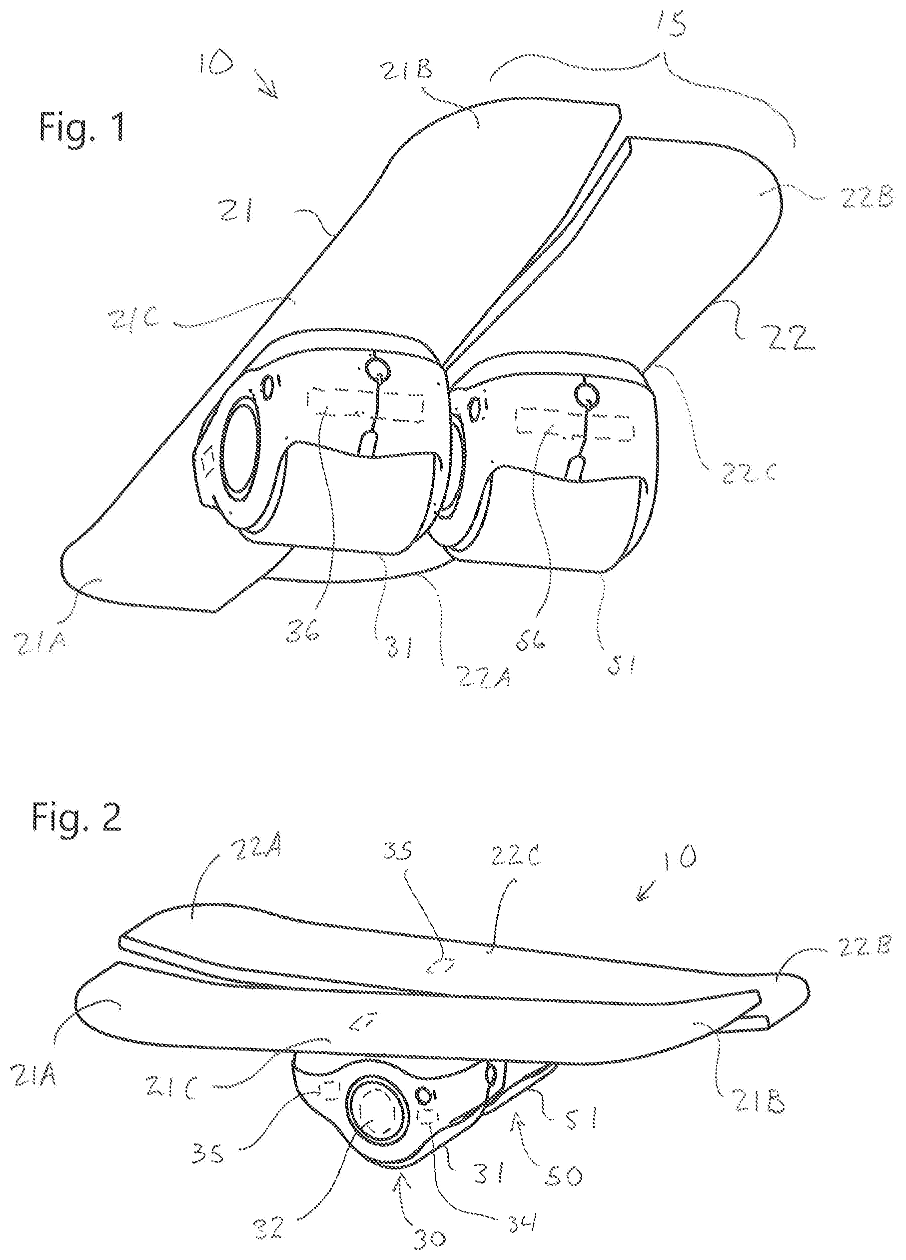
[0011] FIGS. 1-2 are bottom and top perspective views, respectively, of one embodiment of a transportation device in accordance with the present invention.
[0012] FIGS. 3-4 illustrate another embodiment of an auto-balancing device with a longitudinally disposed platform 115 in accordance with the present invention.
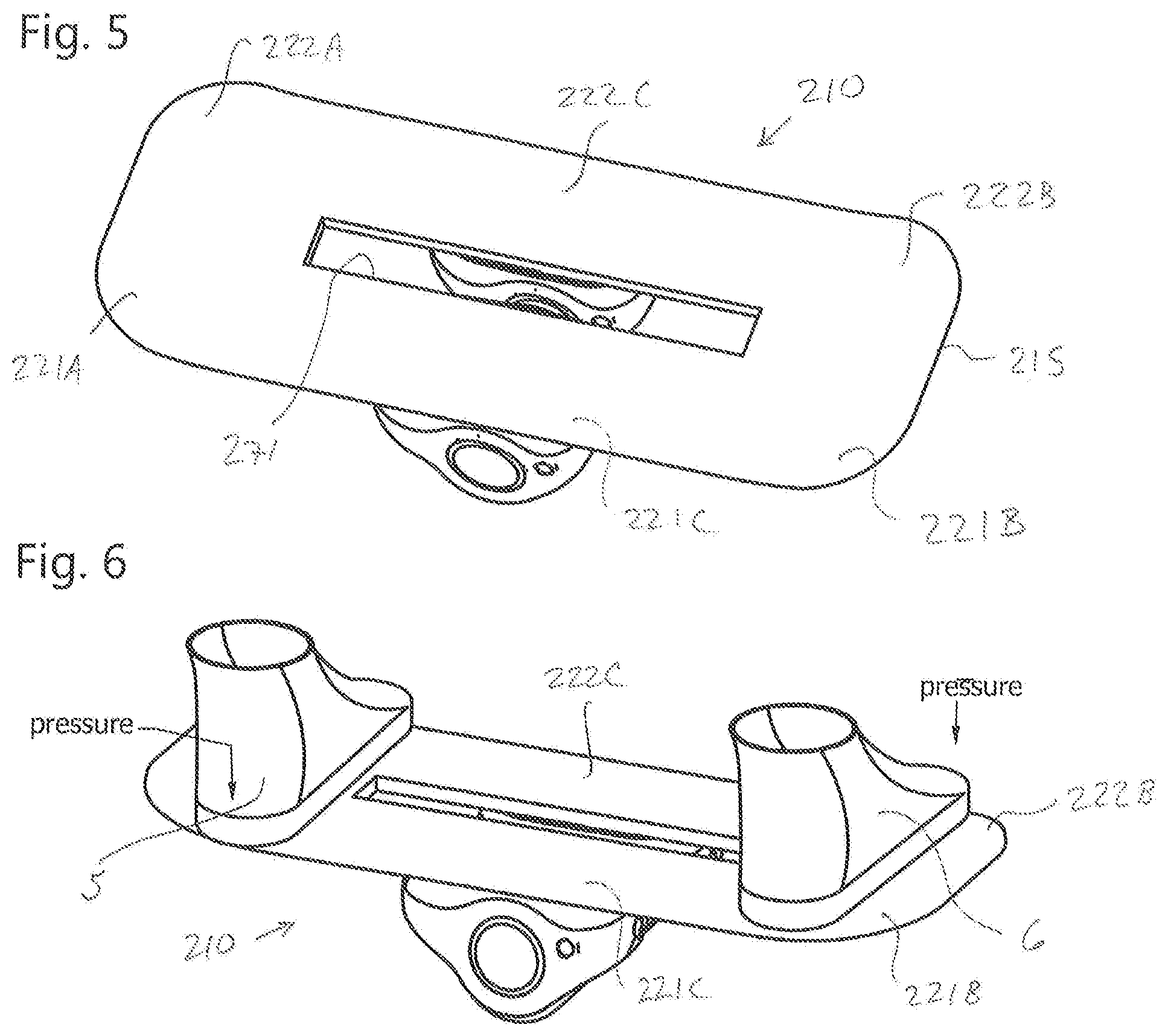
[0013] FIGS. 5-6 illustrate yet another embodiment of an auto-balancing device with a longitudinally disposed platform in accordance with the present invention.
[0014] FIG. 7 is a perspective view of another embodiment of an auto-balancing device in accordance with the present invention in which the drive wheels extend through the platform.
DETAILED DESCRIPTION
[0015] Referring to FIGS. 1 and 2, bottom and top perspective views of a first embodiment of a transportation device 10 in accordance with the present invention are respectively shown.
[0016] Device 10 preferably includes a longitudinally disposed foot platform 15 that has two foot platform sections 21,22, one located on each lateral side of the platform. Below each platform section is an auto-balancing foot platform unit or module (herein "FPU") 30,50. In FIG. 1, platform section 21 is coupled to FPU 30 and platform section 22 is coupled to FPU 50.
[0017] Each FPU preferably has a drive wheel 31,51 and an associated motor 32,52. The motor may be a hub motor or other motor arrangement. Each FPU also preferably has a control circuit 34,54, a position sensor (such as a fore-aft tilt angle sensor or gyroscopic sensor or other sensor) 35,55, and a battery 36,56. Alternatively, the sensor for a given FPU may be provided with the associated platform section. Regardless, the sensors are preferably configured to sense the fore-aft tilt angle of their foot platform section.
[0018] FPUs 30,50 are preferably configured such that the control circuit drives the drive wheel 31,51 towards auto-balancing the FPU based on data from the sensor 35,55. Auto-balancing arrangements, including those for use in an FPU, are known in the art.
[0019] FPUs 30,50 are preferably coupled to one another such that the drive wheels have a common axis of rotation, though they may be otherwise arranged without departing from the present invention.
[0020] Foot platform sections 21,22 each have a front end A, a rear end B, and a connecting member C therebetween. The end portions may be referred to as subsections, such as 21A,22A in the front and 21B,22B in the rear, and the connecting members as 21C,22C. As shown in FIG. 6, a rider would typically stand with a foot on subsections 21A,22A and the other on subsections 21B,22B. By switching weight from heel to ball on their feet, and vice versa, the rider can change the tilt of the connecting member 21C,22C relative to one another and thus achieve turning.
[0021] For example, if in FIG. 2, connecting member 22C is tilted forward by 1 degree and connecting member 21C is tilted forward by 5 degrees, then there is a 4 degree differential between the connecting members and wheel 31 is driven faster than wheel 51, turning device 10 to the right.
[0022] It should be recognized that which longitudinal end is the front or rear may be arbitrary as a rider may mount from either direction (though the device may be made with a dedicated front and rear).
[0023] Note that equal and opposite tilting of the connecting members 21C,22C would allow the device to pivot in place, something prior art auto-balancing skateboard devices cannot achieve.
[0024] By affording independent, or relative difference based, control of two drive wheels, the present invention is able to achieve much more responsive turning than available in prior art devices. Further, it is achieved in a manner that is intuitive to a rider, which makes learning to ride easier, and increases the potential uses of the device--commuting, recreation, games and competitions, etc.
[0025] It should also be recognized that in the present invention, the platform has a greater longitudinal dimension than lateral dimension. This may be simply longer than wide, or 1.5.times. longer, or 2.times. longer or 2.5.times. longer than wide, or more.
[0026] Referring to FIGS. 3-4, another embodiment of an auto-balancing device 110 with a longitudinally disposed platform 115 in accordance with the present invention is shown.
[0027] Device 110 is similar to device 10 and similar components may have the same reference numerals in the tens and ones digits. One difference is that while platform 15 of device 10 is two physically separate items, i.e., not directly connected, the two platform sections 121,122 of platform 115 are coupled by a flexible membrane 140. The membrane is preferably coupled to the platform sections in such a way as to give the feel of one contiguous platform surface yet afford sufficient flexibility such that the platform sections can move in fore-aft tilt relative to one another. The membrane may be made of latex rubber or flexible plastic or other suitable material.
[0028] Similar to device 10, each platform section 121,122 has a front subsection 121A,122A, a rear subsection 121B,122B, and a connecting member 121C,122C therebetween.
[0029] FIG. 4 illustrates one potential assembly technique for device 110. Arrow A indicates the platform being mounted to FPUs 130,150. Platform 115 may be screwed to the FPUs or otherwise fastened. Coupling techniques for joining the FPUs are known in the art.
[0030] Referring to FIGS. 5 and 6, yet another embodiment of an auto-balancing device 210 with a longitudinally disposed platform 215 in accordance with the present invention is shown.
[0031] Device 210 includes a contiguous or one piece platform 215, albeit preferably with a longitudinally disposed hole 271 in it to enhance twisting. Platform 215 preferably has subsections 221A,222A up front, subsections 221B,222B in the rear, and connecting members 221C,222C therebetween.
[0032] FIG. 6 illustrates where a rider might stand. For example, one foot 5 at the front and one foot 6 at the rear. It can be seen that each foot touches a pair of subsections. As a rider leans forward or rearward (in the line of direction of travel) the device will go in that direction, however, when a rider twists the platform longitudinally, the connecting members 221C,222C will experience different fore-aft tilt angles causing the device to turn.
[0033] Referring to FIG. 7, a perspective view of another embodiment of an auto-balancing device 310 with longitudinally disposed platform in accordance with the present invention is shown. Device 310 includes a flexible platform 315 with holes therein. Center hole 371 accommodates two drive wheels 330,350 that extend above the platform's top surface. Holes 372 are provided at the longitudinal ends (at subsections 321A,322A,321B,322B) to facilitate twisting.
[0034] Device 310 operates similar to device 210. A rider standing skateboard style leans forward or rearward to initiate movement and twists the board by alternatively applying weight to the balls and heels of his or her feet. This twisting causes connecting members 321C,322C to have different fore-aft tilt angles, as detected by sensors 335,355, respectively, to achieve a turning of the device.
[0035] While the invention has been described in connection with specific embodiments thereof, it will be understood that it is capable of further modification, and this application is intended to cover any variations, uses, or adaptations of the invention following, in general, the principles of the invention and including such departures from the present disclosure as come within known or customary practice in the art to which the invention pertains and as may be applied to the essential features hereinbefore set forth, and as fall within the scope of the invention and the limits of the appended claims.
* * * * *
D00000
D00001
D00002
D00003
D00004
XML
uspto.report is an independent third-party trademark research tool that is not affiliated, endorsed, or sponsored by the United States Patent and Trademark Office (USPTO) or any other governmental organization. The information provided by uspto.report is based on publicly available data at the time of writing and is intended for informational purposes only.
While we strive to provide accurate and up-to-date information, we do not guarantee the accuracy, completeness, reliability, or suitability of the information displayed on this site. The use of this site is at your own risk. Any reliance you place on such information is therefore strictly at your own risk.
All official trademark data, including owner information, should be verified by visiting the official USPTO website at www.uspto.gov. This site is not intended to replace professional legal advice and should not be used as a substitute for consulting with a legal professional who is knowledgeable about trademark law.