Pellet-fired Cooking Apparatus
Witzel; Terry ; et al.
U.S. patent application number 16/295712 was filed with the patent office on 2020-09-10 for pellet-fired cooking apparatus. The applicant listed for this patent is Onward Multi-Corp Inc.. Invention is credited to Colin Kirvan, Terry Witzel.
| Application Number | 20200281402 16/295712 |
| Document ID | / |
| Family ID | 1000004096672 |
| Filed Date | 2020-09-10 |


View All Diagrams
| United States Patent Application | 20200281402 |
| Kind Code | A1 |
| Witzel; Terry ; et al. | September 10, 2020 |
PELLET-FIRED COOKING APPARATUS
Abstract
A cooking apparatus, having a body defining an interior cooking chamber for cooking food, a pellet supply portion coupled to the body and including a hopper for storing fuel, a combustion chamber for burning the fuel and heating the cooking chamber, a feeding mechanism for supplying fuel from the hopper to the combustion chamber, and a removable collection receptacle located below the combustion chamber. The apparatus also includes an ash-shaker located between the collection receptacle and the combustion chamber, the ash-shaker including an external actuator that controls one or more moving elements located in the combustion chamber, wherein movement of the moving elements encourages unburned debris in the combustion chamber to fall into the receptacle, after which the collection receptacle can be removed and the unburned debris discarded.
| Inventors: | Witzel; Terry; (Waterloo, CA) ; Kirvan; Colin; (Waterloo, CA) | ||||||||||
| Applicant: |
|
||||||||||
|---|---|---|---|---|---|---|---|---|---|---|---|
| Family ID: | 1000004096672 | ||||||||||
| Appl. No.: | 16/295712 | ||||||||||
| Filed: | March 7, 2019 |
| Current U.S. Class: | 1/1 |
| Current CPC Class: | F23L 5/02 20130101; F23K 2900/00 20130101; A47J 37/0704 20130101; F23K 2203/202 20130101; F23K 3/22 20130101 |
| International Class: | A47J 37/07 20060101 A47J037/07; F23K 3/22 20060101 F23K003/22; F23L 5/02 20060101 F23L005/02 |
Claims
1. A cooking apparatus, comprising: a body defining an interior cooking chamber for cooking food; a pellet supply portion coupled to the body and including a hopper for storing fuel; a combustion chamber for burning the fuel and heating the cooking chamber; a feeding mechanism for supplying fuel from the hopper to the combustion chamber; a removable collection receptacle located below the combustion chamber; and an ash-shaker located between the collection receptacle and the combustion chamber, the ash-shaker including an external actuator that controls one or more moving elements located in the combustion chamber, wherein movement of the moving elements encourages unburned debris in the combustion chamber to fall into the receptacle, after which the collection receptacle can be removed and the unburned debris discarded.
2. The cooking apparatus of claim 1, wherein the actuator is sized and shaped to be moved by hand.
3. The cooking apparatus of claim 1, wherein the actuator is sized and shaped to be moved using a tool.
4. The cooking apparatus of claim 1, wherein the moving element include a circular plate with one or more holes.
5. The cooking apparatus of claim 1, further comprising a control panel for controlling the cooking apparatus;
6. The cooking apparatus of claim 1, wherein the fuel includes combustible pellets.
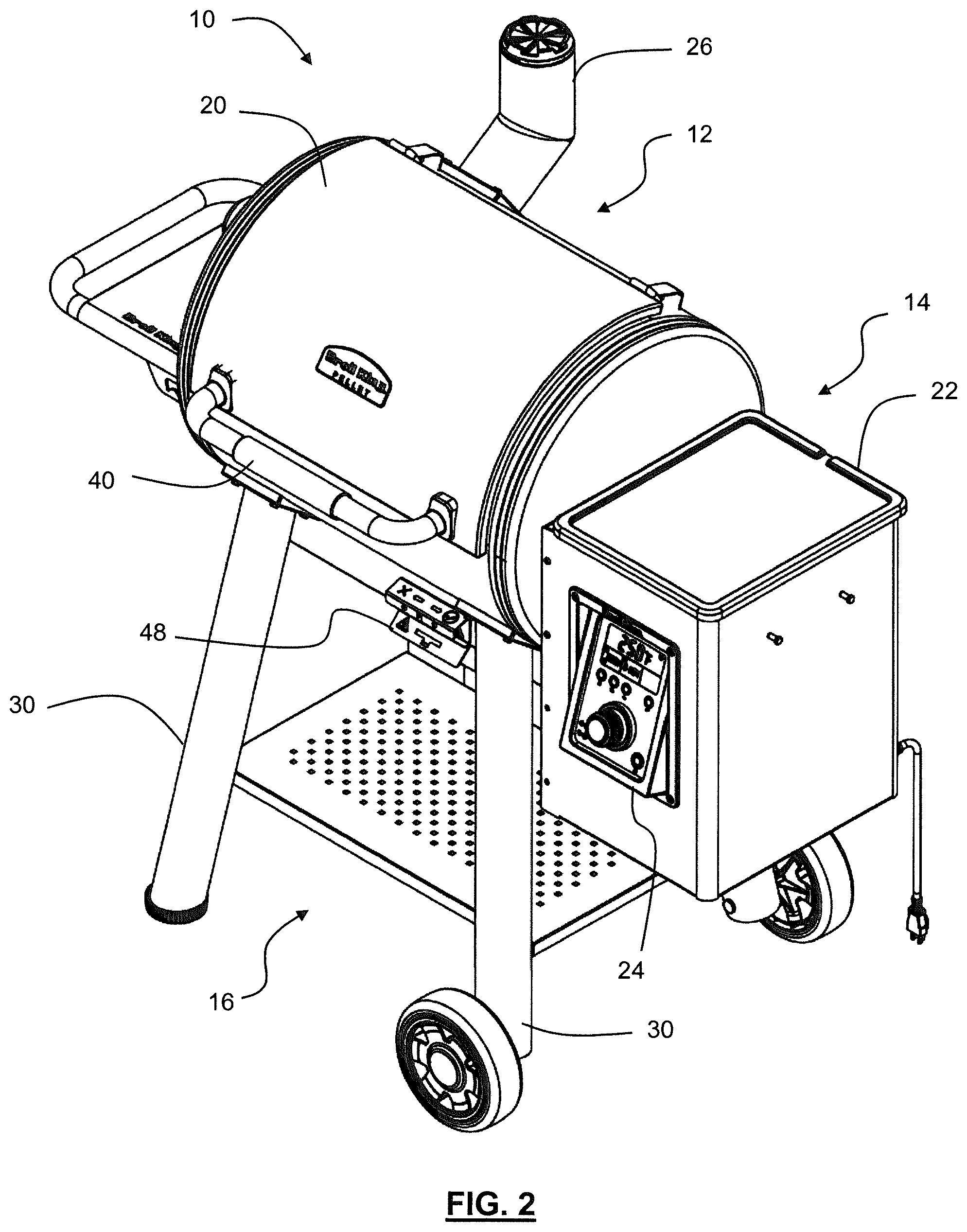
7. The cooking apparatus of claim 1, wherein the fuel includes wood pellets.
8. The cooking apparatus of claim 1, wherein the feeding mechanism is controlled by a controller to ensure that a suitable amount of fuel is provided to the combustion chamber to obtain desired operating temperatures for the cooking apparatus.
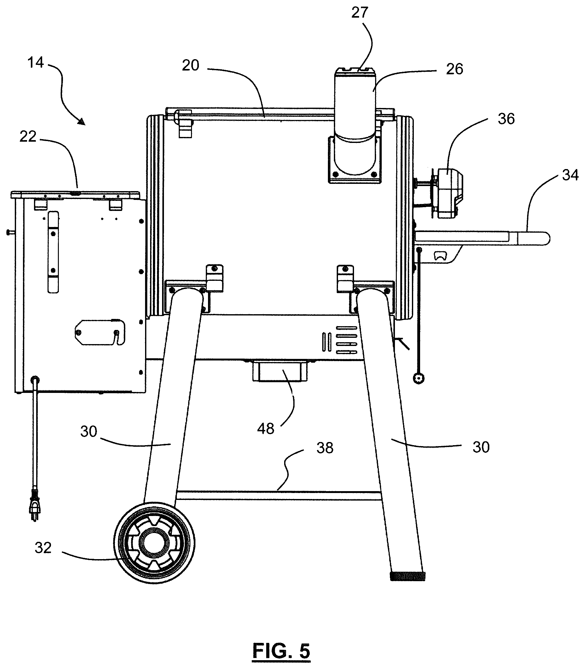
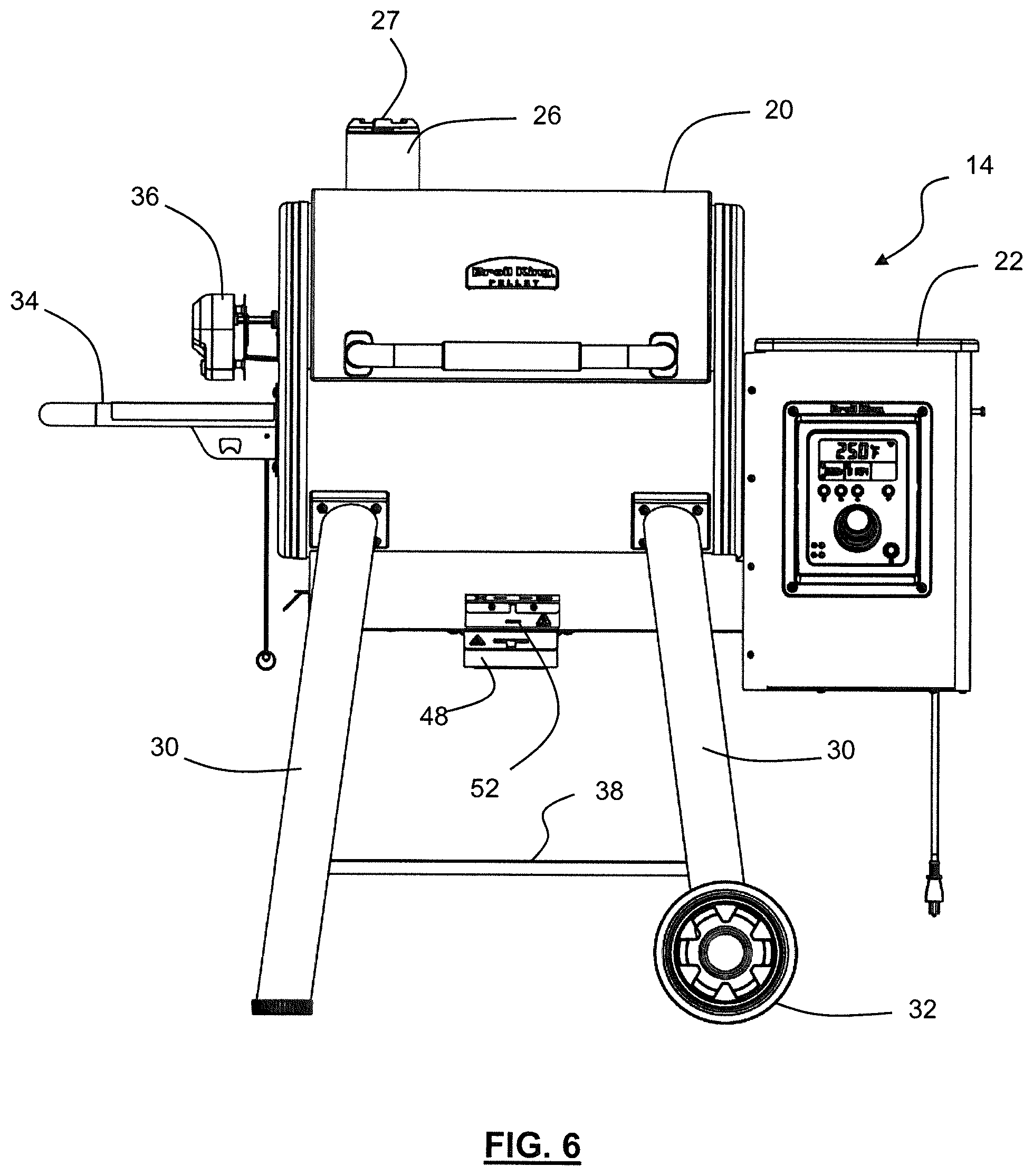
9. The cooking apparatus of claim 1 wherein the pellet supply portion is powered by an electrical power source.
10. The cooking apparatus of claim 1 wherein the feeding mechanism comprises an auger.
11. The cooking apparatus of claim 1, further comprising a heating element in the combustion chamber for burning the fuel.
12. The cooking apparatus of claim 1, further comprising a fan that drives air into the combustion chamber to encourage efficient combustion of the fuel.
13. The cooking apparatus of claim 1, further comprising an actuator for effecting movement of the hopper.
14. The cooking apparatus of claim 13, wherein the actuator includes a vibrating motor.
15. The cooking apparatus of claim 14, wherein the vibrating motor is selectively activated to discourage fuel from sticking in the hopper.
16. The cooking apparatus of claim 1, further comprising a sensor for measuring a quantity of fuel in the hopper.
Description
RELATED APPLICATIONS
[0001] This application claims the benefit of U.S. Provisional Patent Application Ser. No. 62/639,777 filed Mar. 7, 2018 and entitled Pellet-Fired Cooking Apparatus, the entire contents of which are hereby incorporated by reference herein for all purposes.
TECHNICAL FIELD
[0002] The embodiments disclosed herein relate to cooking apparatus such as barbecues and smokers, and, in particular to pellet-fired cooking apparatus that use pellet based fuel, such as wood pellets.
INTRODUCTION
[0003] U.S. Pat. No. 4,823,684 to Traeger is a Pellet-Fired Barbecue, and describes a pellet-fired barbecue including an elevated barbecue pan fired by a pellet-burning pot mounted below the bottom of the barbecue. A heat baffle plate is disposed within the pan above the top of the pot, and forced-air mechanism produces movement of hearted air within the barbecue.
[0004] U.S. Pat. No. 4,989,521 to Traeger is a Gravity Fed Pellet Burner, and describes a gravity operated burner for particulate fuel. Fuel held in a hopper drops downwardly through a fuel tube to fall on an inclined chute. The chute feeds a shelf where burning takes place in a high heat zone. Material on the shelf stops unhindered flow of fuel down the chute.
[0005] U.S. Pat. No. 5,251,607 to Traeger is a Pellet-Fired Cooking Grill, and describes a pellet-fired cooking grill which includes a housing having a grill chamber defined within it. Tubular structure extends downwardly from the base of the chamber and defined within this structure is a burning zone. A hopper holding pellet fuel disposed above and adjacent the burning zone supplied pellets through a gravity operated chute to the burning zone.
BRIEF DESCRIPTION OF THE DRAWINGS
[0006] The drawings included herewith are for illustrating various examples of articles, methods, and apparatuses of the present specification. In the drawings:
[0007] FIG. 1 is a first perspective view of a pellet fired cooking apparatus according to one embodiment;
[0008] FIG. 2 is a second perspective view of the pellet fired cooking apparatus of FIG. 1;
[0009] FIG. 3 is a left-side elevation view of the pellet fired cooking apparatus of FIG. 1;
[0010] FIG. 4 is a right-side elevation view of the pellet fired cooking apparatus of FIG. 1;
[0011] FIG. 5 is a rear elevation view of the pellet fired cooking apparatus of FIG. 1;
[0012] FIG. 6 is a front elevation view of the pellet fired cooking apparatus of FIG. 1;
[0013] FIG. 7 is another perspective view of the pellet fired cooking apparatus of FIG. 1 shown with the lid open;
[0014] FIG. 8 is an exploded perspective view of the pellet fired cooking apparatus of FIG. 1;
[0015] FIG. 9 is an elevation view of the grease tray and pellet feeding auger of the cooking apparatus of FIG. 1 according to one embodiment;
[0016] FIG. 10 is perspective view of the grease tray and pellet feeding auger of FIG. 9;
[0017] FIG. 11 is a perspective view of the enclosed pellet feeding auger and fire pot assembly of the cooking apparatus of FIG. 1 according to one embodiment;
[0018] FIG. 12 is a front elevation view of the enclosed pellet feeding auger and fire pot assembly of FIG. 11;
[0019] FIG. 13 is a left-side elevation view of the enclosed pellet feeding auger and fire pot assembly of FIG. 11;
[0020] FIG. 14 is a right-side elevation view of the enclosed pellet feeding auger and fire pot assembly of FIG. 11;
[0021] FIG. 15 is a perspective view of the enclosed pellet feeding auger and fire pot assembly of FIG. 11 with the front cover removed;
[0022] FIG. 16 is a front elevation view of the enclosed pellet feeding auger and fire pot assembly of FIG. 11 with the front cover removed;
[0023] FIG. 17 is a left-side elevation view of the enclosed pellet feeding auger and fire pot assembly of FIG. 11 with the front cover removed;
[0024] FIG. 18 is a right-side elevation view of the enclosed pellet feeding auger and fire pot assembly of FIG. 11 with the front cover removed;
[0025] FIG. 19 is a cut-away perspective view of the fire pot, auger and air fan of the cooking apparatus of FIG. 1 according to one embodiment;
[0026] FIG. 20 is a cut-away perspective view of the fire pot of the cooking apparatus of FIG. 1 according to one embodiment showing the ash-hole agitator;
[0027] FIG. 21 is a front perspective view of the ash-hole agitator being activated by a tool, such as a grid lifter;
[0028] FIG. 22 is a perspective view of a rotisserie apparatus of the cooking apparatus of FIG. 1 according to one embodiment;
[0029] FIG. 23 is a detailed view of the control panel for the cooking apparatus of FIG. 1 according to one embodiment;
[0030] FIG. 24 is a detailed exploded view of a first portion of the cooking apparatus of FIG. 1 according to one embodiment; and
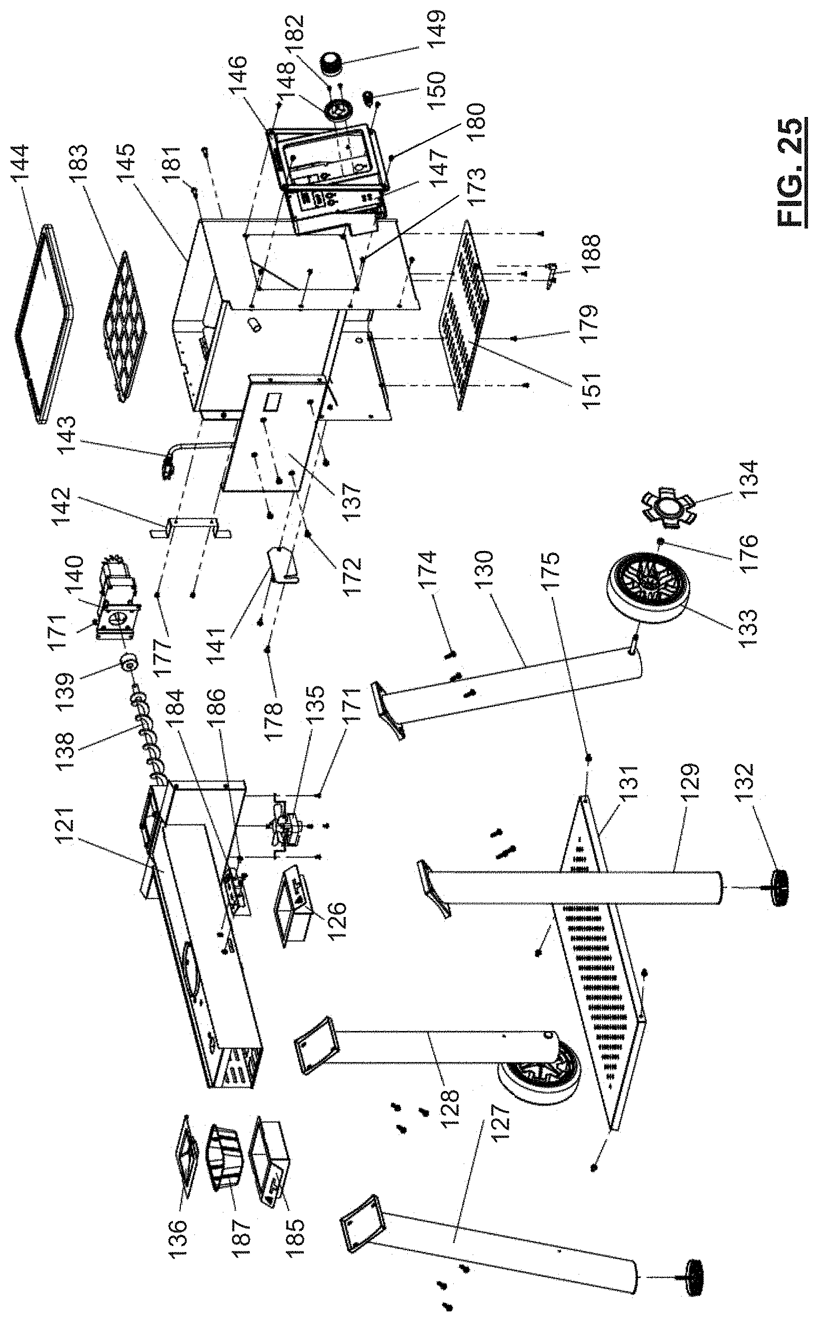
[0031] FIG. 25 is a detailed exploded view of a second portion of the cooking apparatus of FIG. 1 according to one embodiment.
DETAILED DESCRIPTION
[0032] Referring to FIGS. 1 to 8 generally, illustrated therein is a cooking apparatus 10.
[0033] The cooking apparatus 10 includes a body 12 defining an interior cooking chamber C for cooking food. As shown, the body 12 may be supported by a base 16, and the body 12 includes a lid 20 that encloses the cooking chamber C.
[0034] The lid 20 may be adapted to removably cover the cooking chamber C. For example, as shown in FIG. 7, the lid 20 may be hingedly coupled to the chamber bottom 21, and may have a handle 40 for pivoting the lid 20 between open and closed positions.
[0035] The body 12 also includes a chimney 26 for venting exhaust during use. The chimney 26 may include an adjustable valve 27 (i.e., a rotatable plate) to control the amount of exhaust exiting the cooking chamber C (which may be particularly useful during a smoking operation, for example).
[0036] In some embodiments, coupled to the body 12 may be a shelf 34. The shelf 34 as shown is located on one side of the body 12, and can be used for supporting items (i.e., food, sauces, etc.) prior to or during the cooking operation.
[0037] In some embodiments, the cooking apparatus 12 may include a rotisserie 39 (as shown in FIG. 22 for example) for cooking food. The rotisserie 39 may be driven by a motor 36 and may be supported at one or more ends of the body 12.
[0038] Turning now to FIG. 3 for example, in some embodiments the body 12 may include a grease trap 50 for catching grease and other debris that is generated during use of the cooking apparatus 10.
[0039] As also shown the body 12 is coupled to a pellet supply portion 14, which as shown may include a hopper 22 for storing fuel (generally in chamber 42 as shown in FIG. 8). Generally, the fuel will be in the form of combustible pellets (typically wood pellets), which may of different types of wood (hickory, mesquite, etc.) and which may have additives such as flavourings and so on. The pellet supply portion 14 may also include a control panel 24 for controlling the operation of the cooking apparatus 10 (e.g., setting temperatures, pellet feed rates and so on). For example, in some cases the cooking apparatus 10 may be used for high heat cooking (i.e., grilling) or low heat cooking (i.e., smoking) and the temperature of the cooking chamber C can be selected accordingly.
[0040] The pellet supply portion 14 may be powered by a power source, which in some embodiments may be an electrical wall panel connected via a power cord 44.
[0041] In some embodiments, the pellet supply portion 14 may include an actuator (shown schematically as 45) for effecting movement of the hopper 22 and/or chamber 42. In particular, fuel, particularly wood pellets, that are stored in the chamber 42 of the hopper 22 may tend to become stuck or clogged. For instance, some wood pellets may tend to stick to angled sides of the chamber 42, particularly in seams or other locations within the chamber 42. By using an actuator 45, the hopper 22 and/or chamber 42 can be moved to help dislodge pellets that are stuck in the chamber 42. For example, the actuator 45 could include a vibrating motor that. At particular times (such as once every few minutes), the motor could vibrate the chamber 42 to help ensure the pellets flow smoothly and tend not to stick. In some embodiments, the actuator 45 could be actuated automatically, for example by the controller based on a time-based schedule. In some embodiments, the actuator 45 may activate in response to a sensor, for example a sensor that monitors the flow of pellets. In some embodiments, the actuator 45 could be capable of manual actuation, such as by an operator or user of the cooking apparatus 10.
[0042] In some embodiments, the hopper 22 and/or chamber 42 may include one or more devices for measuring the quantity of pellets remaining in the hopper 22. For example, one or more sensors could be used to measure the quantity of pellets. In one example, an optical sensor could be used. In one example, a weight sensor could be used. In one example, the actuator 45 could be pulsed, and a measured vibration response could be used to estimate the quantity of pellets in the hopper 22.
[0043] In some embodiments, the hopper 22 and/or chamber 42 may include one or more drain holes for selectively removing the fuel therefrom. For example, a user may desire to switch the type of fuel in the hopper 22 (i.e., switching from hickory to mesquite wood pellets), or to otherwise remove old fuel. One or more drain holes can be provided that, when opened, allow the fuel to be drained out of the hopper 22.
[0044] The cooking apparatus 10 may also include one or more grates, such as a main grate G and an upper grate UG for supporting food or cookware within the cooking chamber C (see for example FIG. 8). As shown, the body 12 may have a generally cylindrical shape. In other examples, the body 12 may have other shapes.
[0045] Located below the grates G may be one or more grate plates 56, which may be angled to direct grease or other debris that is generated during use of the cooking apparatus 10 into the grease trap 50 via an outlet 58.
[0046] The cooking apparatus 10 also includes a plurality of leg members 30 for supporting the body 22. As shown, there may be four legs 30, which may be located at four corners of the body 12. The legs 30 may help elevate the cooking apparatus 10 above a support surface such as a ground surface, a deck, and so on. In some cases, one or more of the legs 30 may include wheels to allow the cooking apparatus 10 to be moved around more easily.
[0047] In some embodiments, one of more of the legs 30 may be coupled together by a lower shelf 38. The lower shelf 38 can provide for storage during use of the cooking apparatus 10, and may also help stabilize the legs 30.
[0048] Turning now to FIGS. 8 to 21, the operation of the cooking apparatus 10 will be described in reference to some specific internal components thereof. For instance, as shown in FIG. 8, the pellet supply portion 14 includes a combustion chamber 46 for burning pellets. The pellet supply portion 14 also includes a feeding mechanism for supplying pellets from the hopper 22 to the combustion chamber 46, which in this example includes an auger 54. The auger 54 is controlled by a controller (typically by selections made on the control panel 24) and which ensures that a suitable amount of pellets are provided to the combustion chamber 46 to obtain the desired operating temperatures for the cooking apparatus 10. In particular, a heating element (which may be an electric arc or other suitable heating element) in the combustion chamber. A fan 66 may also drive air into the combustion chamber 46 to encourage efficient combustion of the pellets therein, thus reducing the amount of unburned waste product.
[0049] In some embodiments, the size and shape of the auger 54 may be specially selected to ensure good pellet flow from the hopper 22 into the combustion chamber 46. For example, as shown the auger 54 in this example includes a generally elongate rod around which is wrapped a helical member, much like a screw. The angle and pitch of this helical member and the size of the rod can be specifically selected to inhibit binding of the pellets as they travel to the combustion chamber 46.
[0050] In general, the auger 54 may be driven by one or more electric motors, and may be coupled thereto by a gear 60 located in the hopper 22. As seen by inspection of FIG. 9, wood pellets in the hopper 22 can pass through an opening 62 to engage with the auger.
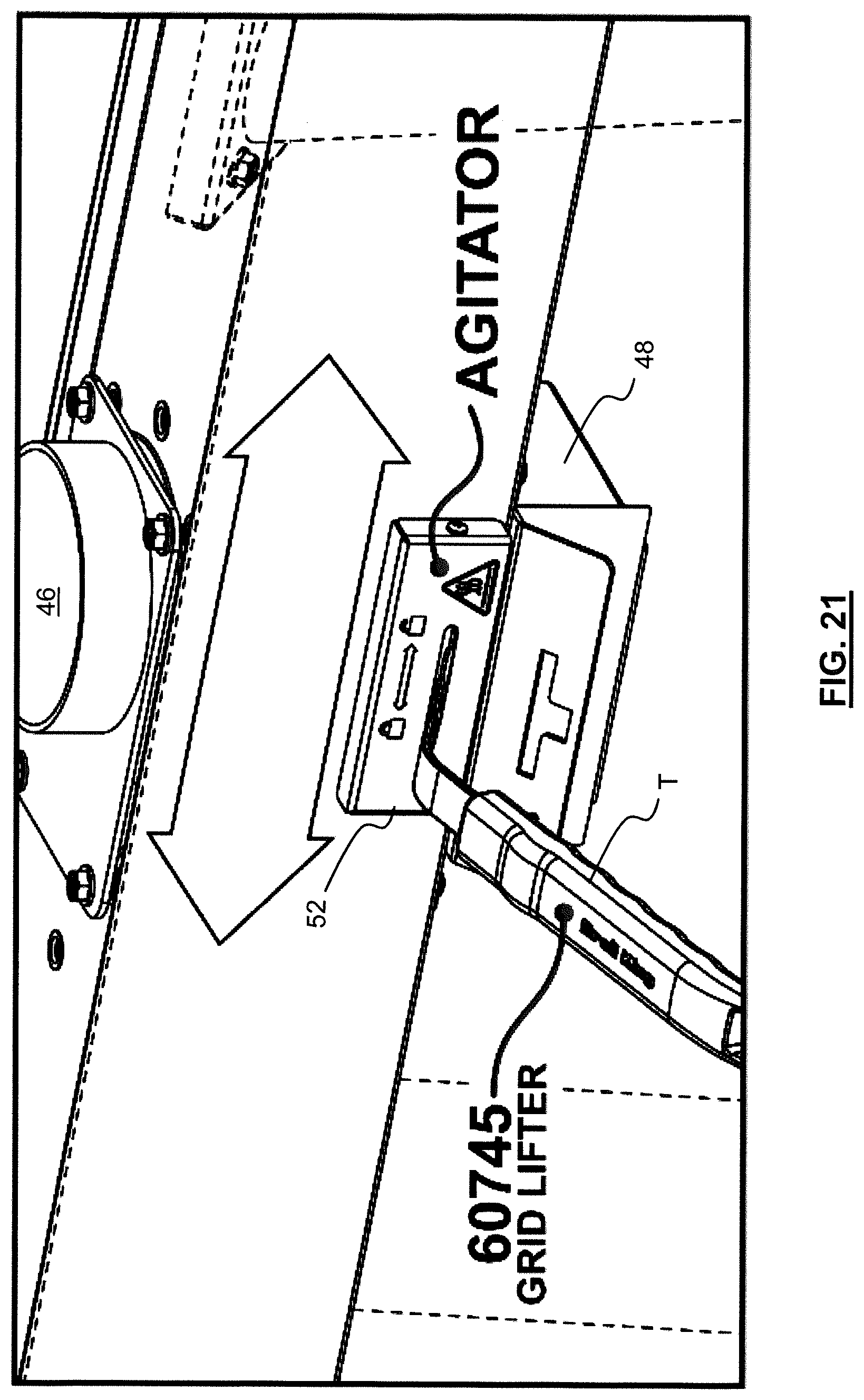
[0051] One or the challenges with the operation of pellet-fired cooking apparatuses generally is the generation of unburned waste product (i.e., unburned ash and other portions of the pellets). Although pellet-fired coking apparatus tend to be relatively efficient, their configuration can make this a problem. In particular, the combustion chamber 46 tends to be cylindrical and of relatively small size. This helps to ensure efficient combustion. However, the small size means that any unburned waste products tends to accumulate in the combustion chamber 46, and can quickly interfere with the operation of the cooking apparatus 10. For example, some prior art cooking apparatuses require the combustion chamber to be regularly cleaned by vacuuming it out, which often requires a substantial disassembly of all or a portion of such cooking apparatuses.
[0052] Located below the combustion chamber 46 according to the present teachings, however, is an as collection receptacle 48. Located generally between the receptacle 48 and the combustion chamber 46 is an ash-shaker. More specifically, the ash-shaker includes an external actuator 52 that controls one or more moving elements 64 in the bottom of the combustion chamber 46. As shown in FIG. 20 for example, the moving element 64 in this embodiment include a circular plate with several holes. These holes cooperated with holes in the bottom of the combustion chamber 46. When ash or other unburned debris builds up in the combustion chamber 46, the actuator 52 can be moved, rotating or otherwise moving the moving element 64 and allowing the unburned debris to fall out of the combustion chamber and into the receptacle 48. The receptacle 48 can then be removed and the unburned debris discarded. In this manner, the combustion chamber 46 can be cleaned out without needing to substantially dismantle the cooking apparatus 10.
[0053] In some embodiments, the moving element 64 may have other shapes, and could for instance be rectangular.
[0054] In some embodiments, the actuator 52 can be actuated by hand. In some embodiments, the actuator 52 is designed to be used with a tool T (such as a grid lifter--see FIG. 21). This can help facilitate operation of the actuator 52, particularly then the cooking apparatus 10 is hot.
[0055] Turning now to FIG. 23, illustrated therein is a detailed view of the control panel 24 of the cooking apparatus 10.
[0056] Control panel 24 in this embodiment includes a main display 70, which can show details such as the desired or actual operating temperature of the cooking apparatus 10 (which may be measured by a probe installed in the cooking chamber C). Control panel 24 may also include a main control knob 72 for selecting the desired operating temperature.
[0057] Control panel 24 may also include probe ports 74, 76 for coupling to one or more probe thermometers (i.e., meat thermometers), which can be used to measure the temperature of food products being cooked. The measured temperatures can be displayed on secondary displays 75, 77. Another display 78 may also show time information, such as elapsed time, a timer, and so one.
[0058] The control panel 24 may also include a power button 80 for turning the cooking apparatus on and off).
[0059] The control panel 24 may also include preset temperature buttons operable to select particular cooking temperatures, such as a first button 82 for smoking food, a second button 84 for poultry, and a third button 86 for high heat grilling.
[0060] The control panel 24 may also include a settings button 88, which may allow a user to adjust one or more characteristics of the cooking apparatus 10. This could include, for instance, adjusting the auger speed, activating the rotisserie 39, and so on.
[0061] Turning lastly to FIGS. 24-25, illustrated therein are detailed exploded views of the various components of the cooking apparatus of FIG. 1 according to one embodiment, while Table 1, below, details the parts referred to.
TABLE-US-00001 TABLE 1 Parts of FIGS. 24 and 25. Reference Number Description 101 Main Lid Weld Assembly 102 Nameplate - Pellet 103 Handle Seat 104 Lid Handle Assembly 105 Glass Fibre 106 Warming Rack 107 Cask Cooking Grid 108 Guide Plate-Grease Tray 109 Heat Deflector Assembly 110 Grease Tray Weld Assembly 111 Grease Tray 112 Radiant Panel 113 Chimney Weld Assembly 114 Damper Bottom 115 Damper Top 116 Burner Cover 117 Fire Pot Weld Assembly 118 Hot Rod 119 Body Weld Assembly Pellet 120 Pellet Probe 121 Pay-off Panel Weld Assembly 122 Side Handle Weld Assembly 123 Rotisserie Support 124 Side Shelf 125 Rotisserie Cap Assy 126 Ash Pan Weld Assembly 127 Leg Rear Weld Assembly-LH 128 Leg Rear Weld Assembly-RH 129 Leg Front Weld Assembly-LH 130 Let Front Weld Assembly-RH 131 Cart Base 132 Balance Foot 133 Wheel Assembly 134 Wheel Hub Cap 135 Air Fan 136 Cover - Grease Tray 137 Hopper Panel Assembly - Left 138 Pellet Auger 139 Auger Sleeve 140 Auger Motor 141 Fuel Door 142 Wire Bracket 143 Power Cord 144 Pellet Box Lid Assembly 145 Pellet Box Assembly 146 PCB Outer Cover Assembly 147 Pellet Controller 148 Knob Bezel 149 Control Knob - Small 150 Switch With LED Ring 151 Pellet Box Patch B 152 Rotisserie Bracket 153 Motor 154 Rotisserie Support 155 Spit Rod 156 Rotisserie Meat Forks 157 Counter Weight Washer 158 Rotisserie Counter Weiqht 159 Rotisserie Collar 160 Thumb Screw 161 Screw 162 Bolt 163 Vent Bolt 164 Screw 165 Screw 166 Butterfly Screw 167 Screw 168 Bolt 169 Screw 170 Bolt 171 Screw 172 Bolt 173 Screw 174 Screw 175 Bolt 176 Lock Nut M8 177 Screw 178 Pellet Bolt 179 Screw 180 Screw 181 Carriage Bolt-Tool Hook 182 Screw 183 Pellet Mesh Assembly 184 Damper Base 185 Grease Tray Base 186 Pellet Bolt 187 Grease Tray 188 WIFI Receive Great Assembly 189 Butterfly Nut 190 SS Burner Damper Assembly
[0062] While the above description provides examples of one or more apparatus, methods, or systems, it will be appreciated that other apparatus, methods, or systems may be within the scope of the present description as interpreted by one of skill in the art.
* * * * *
D00000
D00001
D00002
D00003
D00004
D00005
D00006
D00007
D00008
D00009
D00010
D00011
D00012

D00013

D00014
D00015

D00016

D00017

D00018
XML
uspto.report is an independent third-party trademark research tool that is not affiliated, endorsed, or sponsored by the United States Patent and Trademark Office (USPTO) or any other governmental organization. The information provided by uspto.report is based on publicly available data at the time of writing and is intended for informational purposes only.
While we strive to provide accurate and up-to-date information, we do not guarantee the accuracy, completeness, reliability, or suitability of the information displayed on this site. The use of this site is at your own risk. Any reliance you place on such information is therefore strictly at your own risk.
All official trademark data, including owner information, should be verified by visiting the official USPTO website at www.uspto.gov. This site is not intended to replace professional legal advice and should not be used as a substitute for consulting with a legal professional who is knowledgeable about trademark law.