Cosmetic Product Applicator
Salciarini; Christian
U.S. patent application number 16/319070 was filed with the patent office on 2020-09-10 for cosmetic product applicator. This patent application is currently assigned to Chanel Parfums Beaute. The applicant listed for this patent is Chanel Parfums Beaute. Invention is credited to Christian Salciarini.
| Application Number | 20200281345 16/319070 |
| Document ID | / |
| Family ID | 1000004867597 |
| Filed Date | 2020-09-10 |


View All Diagrams
| United States Patent Application | 20200281345 |
| Kind Code | A1 |
| Salciarini; Christian | September 10, 2020 |
Cosmetic Product Applicator
Abstract
The cosmetic product applicator has an arithmetic mean height S.sub.a of a surface of the applicator in at least one portion A of the applicator that is strictly greater than 10.0 .mu.m, this height being calculated in accordance with the following formula: S a = 1 A .intg. .intg. A z ( x , y ) dxdy , ##EQU00001## in which: A is the portion of the applicator in question, and x, y and z represent the coordinates of the surface of the applicator in an orthogonal system of Cartesian coordinates, with z corresponding to a measurement axis of the height.
| Inventors: | Salciarini; Christian; (Hyeres, FR) | ||||||||||
| Applicant: |
|
||||||||||
|---|---|---|---|---|---|---|---|---|---|---|---|
| Assignee: | Chanel Parfums Beaute Neuilly-sur-Seine FR |
||||||||||
| Family ID: | 1000004867597 | ||||||||||
| Appl. No.: | 16/319070 | ||||||||||
| Filed: | July 18, 2017 | ||||||||||
| PCT Filed: | July 18, 2017 | ||||||||||
| PCT NO: | PCT/FR2017/051953 | ||||||||||
| 371 Date: | May 26, 2020 |
| Current U.S. Class: | 1/1 |
| Current CPC Class: | A46B 2200/1053 20130101; A46B 9/021 20130101; A46D 1/0207 20130101 |
| International Class: | A46B 9/02 20060101 A46B009/02; A46D 1/00 20060101 A46D001/00 |
Foreign Application Data
| Date | Code | Application Number |
|---|---|---|
| Jul 19, 2016 | FR | 1656879 |
Claims
1. A cosmetic product applicator comprising an arithmetic mean height S.sub.a of a surface of the cosmetic product applicator in at least one portion A of the cosmetic product applicator is strictly greater than 10.0 .mu.m, this arithmetic mean height being calculated in accordance with the following formula: S a = 1 A .intg. .intg. A z ( x , y ) dxdy ##EQU00006## in which: A is the portion of the applicator in question, and x, y and z represent the coordinates of the surface of the applicator in an orthogonal system of Cartesian coordinates, with z corresponding to a measurement axis of the arithmetic mean height.
2. The applicator according to claim 1, wherein the arithmetic mean height S.sub.a of the surface of the applicator in the portion A is greater than 15.0 .mu.m.
3. The applicator according to claim 1, wherein a maximum pit height S.sub.v of the surface of the applicator in the portion A is less than 200 .mu.m.
4. The applicator according to claim 1, wherein a developed interfacial area ratio S.sub.dr of the surface of the applicator in the portion A of the applicator calculated according to the formula: S dr = 1 A [ .intg. .intg. A ( [ 1 + ( .differential. z ( x , y ) .differential. x ) 2 + ( .differential. z ( x , y ) .differential. y ) 2 ] - 1 ) dxdy ] ##EQU00007## is greater than 70%.
5. The applicator according to claim 1, wherein the applicator is a cosmetic product applicator for the eyelashes, eyebrows, lips or skin.
6. The applicator according to claim 1, wherein the applicator comprises a body and protuberances, the portion A comprising one or more protuberances or parts of protuberances.
7. The applicator according to claim 1, wherein the applicator is manufactured by additive synthesis, preferably by powder bed fusion.
8. The cosmetic article comprising an applicator according to claim 1.
9. A method of manufacturing a cosmetic product applicator by powder bed fusion, implemented so as to obtain an applicator whose arithmetic mean height S.sub.a of a surface of the applicator in at least one portion A of the applicator is greater than 10.0 .mu.m, this arithmetic mean height being calculated in accordance with the following formula: S a = 1 A .intg. .intg. A z ( x , y ) dxdy ##EQU00008## in which: A is the portion of the applicator in question, and x, y and z represent the coordinates of the surface of the applicator in an orthogonal system of Cartesian coordinates, with z corresponding to a measurement axis of the arithmetic mean height.
10. The method according to claim 1, comprising at least a step of selecting powder grains which have a largest dimension of less than 80.0 .mu.m.
11. The method according to claim 10, wherein the powder grains are selected by sieving.
12. The method according to claim 9, comprising at least a sandblasting step.
13. The method according to claim 12, wherein the sandblasting is carried out in an automatic drum sandblasting booth.
14. The method according to claim 13, wherein abrasive media including grains having a largest dimension between 4.0 and 140.0 .mu.m are used.
15. The method according to claim 14, wherein the abrasive media used are selected from the group consisting of: microbeads; sodium bicarbonate; and compressed fruit stones.
16. The method according to claim 9, comprising a step of cleaning by ultrasound.
17. The method according to claim 16, wherein the frequency of the ultrasound used is between 25 kHz and 45 kHz.
18. The method according to claim 9, wherein the powder in the powder bed fusion step is selected from the thermoplastic polymers of the family of aliphatic polyamides.
19. The applicator according to claim 2, wherein the arithmetic mean height S.sub.a of the surface of the applicator in the portion A is between 15.0 and 30.0 .mu.m.
20. The applicator according to claim 3, wherein a maximum pit height S.sub.v of the surface of the applicator in the portion A is between 80 and 150 .mu.m.
21. The applicator according to claim 4 wherein the developed interfacial area ratio S.sub.dr of the surface of the applicator in the portion A of the applicator is greater than 100%
Description
FIELD OF THE INVENTION
[0001] The invention relates to cosmetic product applicators.
BACKGROUND OF THE INVENTION
[0002] A mascara article, or "mascara", typically comprises a case, a mascara container and an applicator. There are several types of applicator, bottle brush type, injected type and those manufactured by additive synthesis. A bottle brush type applicator has a brush which comprises bristles formed by fibers trapped in a twisted metal wire forming the core of the applicator. An injected applicator is a single piece and comprises plastic bristles or teeth for example. An applicator manufactured by additive synthesis also generally consists of a single piece and may be made for example of a thermoplastic polymer powder. Such applicators give the user satisfactory results. However, she is always looking for better make-up effects.
SUMMARY OF THE INVENTION
[0003] An object of the invention is therefore to improve the cosmetic product applicators.
[0004] Thus, the invention provides for a cosmetic product applicator having an arithmetic mean height S.sub.a of a surface of the applicator in at least one portion A of the applicator that is strictly greater than 10.0 .mu.m, this height being calculated in accordance with the following formula:
S a = 1 A .intg. .intg. A z ( x , y ) dxdy ##EQU00002##
[0005] in which:
[0006] A is the portion of the applicator in question, and
[0007] x, y and z represent the coordinates of the surface of the applicator in an orthogonal system of Cartesian coordinates, with z corresponding to a measurement axis of the height.
[0008] This arithmetic mean height S.sub.a is calculated in accordance with standard ISO 25178.
[0009] The surfaces of the make-up areas of the body on which the cosmetic products are applied generally have a surface state whose roughness is of the order of the .mu.m. A surface of an applicator having an arithmetic mean height S.sub.a according to the invention has a roughness which allows it to increase its surface state compared with conventional applicators and therefore increase its interactions with the area to be made up, for example the user's skin, eyelashes, eyebrows or lips. Increasing these interactions allows better transfer of the product from the surface of the applicator to the surface to be made up, which simplifies the make-up operation, in particular by not having to repeat the same movements.
[0010] The order of magnitude of the arithmetic mean height S.sub.a of an applicator according to the invention therefore corresponds to that of the eyelashes, eyebrows, hairs and epidermis, which improves the contact friction between the applicator and the make-up areas.
[0011] Preferably, the arithmetic mean height S.sub.a of the surface of the applicator in the portion A is greater than 15.0 .mu.m, and preferably between 15.0 and 30.0 .mu.m.
[0012] These values represent a good compromise between the desired beneficial effect and the costs necessary to obtain these characteristics.
[0013] Advantageously, a maximum pit height S.sub.v of the surface of the applicator in the portion A of the applicator is less than 200 .mu.m, and preferably between 80 and 150 .mu.m.
[0014] This therefore avoids cavities that are too large and which could trap product. In this case, some of the product would be lost since not used for make-up. In addition, this accumulation of product in these cavities is likely to make the applicator less efficient and cause premature wear of the applicator. An applicator according to the invention therefore has a longer lifetime.
[0015] Advantageously, a developed interfacial area ratio S.sub.dr of the surface of the applicator in the portion A of the applicator calculated according to the formula:
S dr = 1 A [ .intg. .intg. A ( [ 1 + ( .differential. z ( x , y ) .differential. x ) 2 + ( .differential. z ( x , y ) .differential. y ) 2 ] - 1 ) dxdy ] ##EQU00003##
[0016] is greater than 70%, preferably greater than 100%.
[0017] This characteristic reflects the fact that the surface of the applicator is increased and therefore creates a larger contact surface with the make-up area and therefore a more efficient transfer of product between the applicator and this make-up area.
[0018] Preferably, the applicator is a cosmetic product applicator for the eyelashes, eyebrows, lips or skin.
[0019] For example, the applicator could be a mascara applicator, a lipstick or gloss applicator or an eyeliner.
[0020] Advantageously, the applicator comprises a body and protuberances, the portion A comprising one or more protuberances or parts of protuberances.
[0021] Since it is these parts which are intended mainly to come into contact with the make-up area, their surface state characteristics should preferably be as described in this application. Obviously, these characteristics could also concern other portions of the applicator, for example the body of the applicator which is also used sometimes for make-up.
[0022] Advantageously, the applicator is manufactured by additive synthesis, preferably by powder bed fusion.
[0023] The invention also provides for a cosmetic article comprising an applicator according to any one of the preceding claims.
[0024] The invention further provides for a method of manufacturing a cosmetic product applicator by powder bed fusion, implemented so as to obtain an applicator whose arithmetic mean height S.sub.a of a surface of the applicator in at least one portion A of the applicator is strictly greater than 10.0 .mu.m, this height being calculated in accordance with the following formula:
S a = 1 A .intg. .intg. A z ( x , y ) dxdy ##EQU00004##
[0025] in which:
[0026] A is the portion of the applicator in question, and
[0027] x, y and z represent the coordinates of the surface of the applicator in an orthogonal system of Cartesian coordinates, with z corresponding to a measurement axis of the height.
[0028] The advantages of these characteristics are the same as those described previously with reference to the applicator. In particular, they allow better control of the final surface state of the applicator.
[0029] A powder bed fusion method consists in producing objects from powder materials using one or more lasers to selectively melt the powder particles on the surface of the powder bed, layer by layer, in a closed chamber. Any type of powder suitable for such a method can be used.
[0030] The applicator can be manufactured by powder-based additive manufacturing methods. Manufacture by powder bed fusion is one of the powder-based additive manufacturing methods that can be used to manufacture the applicator. A powder binding method can also be used. A powder binding method consists in producing objects from powder materials using a binding agent in order to selectively consolidate the powder particles on the surface of the powder bed. Any type of powder suitable for such a method can be used.
[0031] The arithmetic mean height of a surface of the applicator could be between 15.0 .mu.m and 30.0 .mu.m.
[0032] Preferably, the method comprises at least a step of selecting powder grains which have a largest dimension of less than 80.0 .mu.m.
[0033] Thus, this selection step which is carried out on the powder, therefore before the formation of the applicator (pre-treatment) allows better control of the final surface state of the applicator and in particular reduces the roughness of the applicator. Only grains having a largest dimension less than 120 .mu.m could be selected, preferably less than 70 .mu.m, for example less than 60.0 .mu.m, or even less than 50.0 .mu.m.
[0034] Preferably, the grains are selected by sieving.
[0035] Several types of sieving can be considered to separate the grains having a largest dimension greater than 80.0 .mu.m from the other grains. For example, sieving by ultrasound, micro-vibration and/or blowing can be used.
[0036] Advantageously, the method comprises at least a sandblasting step.
[0037] Such a step also allows better control of the final surface state of the applicator. This sandblasting is generally carried out in post-treatment, in other words once the applicator has been formed. This sandblasting is carried out in particular to clean the applicator using an abrasive medium (microbeads, bicarbonate, compressed fruit stones, etc.).
[0038] Preferably, the sandblasting is carried out in an automatic drum sandblasting booth, preferably using microbeads.
[0039] Once again, this characteristic provides better control of the final surface state of the applicator.
[0040] More preferably, abrasive media including grains having a largest dimension between 4.0 and 140.0 .mu.m are used. Abrasive media having grains of largest dimension between 40.0 and 100.0 .mu.m could be used, for example between 60.0 and 80.0 .mu.m. Advantageously, the abrasive media used are selected from at least: [0041] microbeads, for example glass or ceramic microbeads; [0042] sodium bicarbonate; or [0043] compressed fruit stones.
[0044] The sandblasting step is carried out, preferably using up to 1000 brushes, in a rotating drum comprising a nozzle projecting silica beads of 4 to 45 .mu.m at a pressure of between 5 bars (510.sup.5 Pa) and 7 bars (710.sup.5 Pa), preferably 6 bars (610.sup.5 Pa) for at least 20 minutes, even 30 minutes.
[0045] The distance from the nozzle to the bottom of the drum is an important parameter. In this case, the nozzle is positioned 350 mm from the bottom.
[0046] The rotating drum also comprises a lateral nozzle, used to detach the brushes from the bottom for better mixing. The pressure of the lateral nozzle is between 2 bars (210.sup.5 Pa) and 4 bars (410.sup.5 Pa), preferably 3 bars (310.sup.5 Pa).
[0047] The brushes rotate at a given speed in the drum. The speed is between 3 and 6 rpm, preferably 4 rpm.
[0048] Advantageously, a blowing step is carried out before the sandblasting step, in the drum of the sandblasting machine with the brushes rotating. This blowing step removes most of the particles of material (PA 11) before the sandblasting step.
[0049] Optionally, the method comprises an alternative step of cleaning by ultrasound.
[0050] The roughness of the applicator can therefore be controlled more precisely. In addition, the roughness can be adjusted depending on the type of applicator to be manufactured.
[0051] Advantageously, the frequency of the ultrasound used is between 25 kHz and 45 kHz.
[0052] This frequency range gives particularly satisfactory cleaning results. The ultrasound is generally applied during post-treatment after immersing the applicator in a suitable solution, for example a 50% solution of isopropyl alcohol. Obviously, other solutions can be used.
[0053] Preferably the powder is selected from the thermoplastic polymers of the family of aliphatic polyamides.
[0054] Obviously, several types of powder can be used, alone or mixed.
BRIEF DESCRIPTION OF THE DRAWINGS
[0055] We will now describe embodiments of the invention given as non-limiting examples in reference to the drawings, in which:
[0056] FIG. 1 is a perspective view of an embodiment of an applicator according to the invention;
[0057] FIGS. 2A and 2B are perspective views of a free end respectively of an applicator according to an embodiment of the invention and of a silicone applicator made by injection;
[0058] FIG. 3 is a diagram of an embodiment of the method according to the invention;
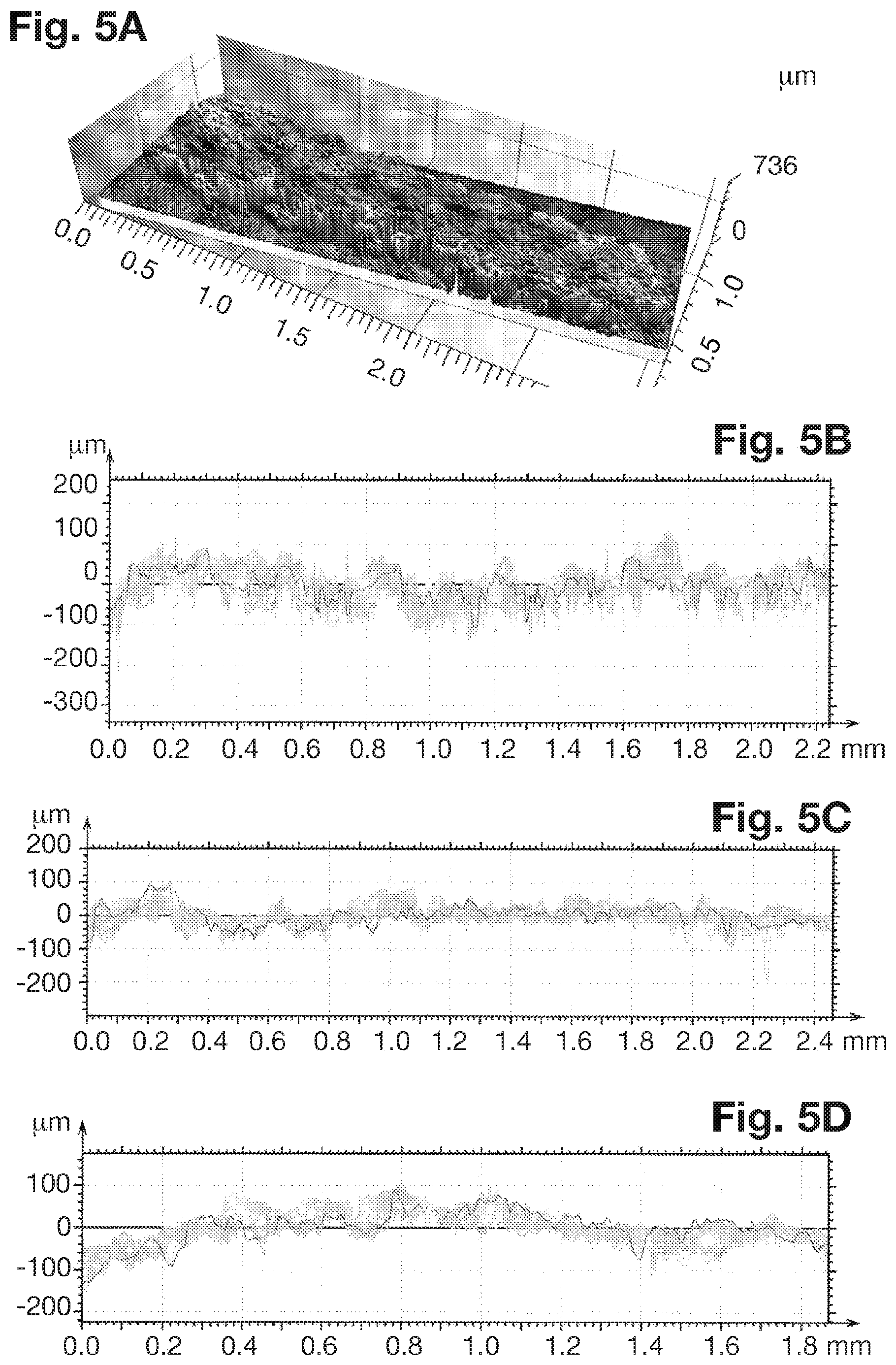
[0059] FIGS. 4A, 5A and 6A are three-dimensional views respectively of a plastic applicator manufactured by injection, of an applicator according to the invention for which there was no sandblasting step during its manufacture by additive synthesis and of an applicator according to the invention for which there was a step of sandblasting during its manufacture by additive synthesis.
[0060] FIGS. 4B to 4D, 5B to 5D and 6B to 6D are graphs showing the roughness profile of the respective applicators of FIGS. 4A, 5A and 6A.
DETAILED DESCRIPTION OF THE INVENTION
[0061] We will now describe embodiments of the applicator and of the method according to the invention, in reference to FIGS. 1 to 6D. We will describe here a mascara applicator but, obviously, it could be another cosmetic product applicator, for example a cosmetic product applicator for the lips, the eyebrows or the skin.
[0062] The mascara applicator 1 according to the invention is carried by a rod 2 which, in a cosmetic article, connects the applicator to a cap. The applicator has an elongate ovoid general shape along its longitudinal axis 3. The rod has a cylindrical rectilinear general shape and its longitudinal axis is coincident with the longitudinal axis 3 of the applicator. The rod and the applicator are connected together by one of their ends (see FIG. 1).
[0063] The applicator 1 may have other general shapes, for example a spherical, parallelelipedic, curvilinear or cubic general shape.
[0064] The applicator comprises a body or core from which the protuberances 4 extend. Obviously, the applicator according to the invention could be an applicator with no core. These protuberances form in this case rows parallel to the axis and rings located in planes perpendicular to the axis.
[0065] The manufacturing method is carried out according to the steps described in the diagram of FIG. 3. Obviously, other steps could be added to this method and some steps could be replaced by another step.
[0066] In this case, we are describing a method of manufacturing a mascara applicator by additive synthesis, more specifically, a powder bed fusion method. This method consists in producing objects from powder materials using one or more lasers to selectively melt the powder particles on the surface of the powder bed, layer by layer, in a closed chamber. In the embodiment described, the type of powder used is a thermoplastic polymer from the family of aliphatic polyamides. We may mention in particular polyamide powders PA11 and PA12. Obviously, several other types of powder can be used, alone or mixed.
[0067] To control the final surface state of the applicator and give it the required characteristics, pre-treatment is carried out on the powder to remove powder grains whose largest dimension is greater than 80.0 .mu.m. In the present case, this pre-treatment includes sieving the powder before using the powder in a conventional powder bed fusion machine. In this case, sieving by ultrasound is used. Obviously, any sieving technique capable of selecting the powder grains whose largest dimension is less than 80.0 .mu.m can be used. Selection of these grains therefore allows better control of the final roughness of the surface of the applicator.
[0068] The sieved powder then undergoes fusion on a conventional powder bed. To do this, the additive synthesis machine uses a digital file representing the applicator geometrically. The file is obtained after designing the applicator on computer-aided design (CAD) software. This file can be in STL format or any other standard file format suitable for additive synthesis by powder bed fusion. The file is then processed by software supplied by the manufacturer of the machine used to carry out the additive synthesis. This software breaks down the file into sections in the form of about hundred digital images in SLI or BFF format, each image corresponding to a layer of the model to be printed, i.e. to a section of the applicator taken in a plane perpendicular to its longitudinal axis. This data is then sent to the printer to produce the applicator.
[0069] To obtain an applicator having a surface state close to the preferred ranges, post-treatment steps are carried out after synthesizing the applicator.
[0070] In the present case, a sandblasting step is carried out in an automatic drum sandblasting booth using microbeads to clean the applicators manufactured, with an abrasive. In this case, glass microbeads of diameter between 4.0 and 140.0 .mu.m are used. This technique produces applicators with the required characteristics. Obviously, other sandblasting techniques can be used.
[0071] The sandblasting step is carried out, preferably using up to 1000 brushes, in a rotating drum comprising a nozzle projecting silica beads of 4 to 45 .mu.m at a pressure of between 5 bars (510.sup.5 Pa) and 7 bars (710.sup.5 Pa), preferably 6 bars (610.sup.5 Pa) for at least 20 minutes, preferably 30 minutes.
[0072] The distance from the nozzle to the bottom of the drum is in this case 350 mm.
[0073] The rotating drum also comprises a lateral nozzle, used to detach the brushes from the bottom for better mixing. The pressure of the lateral nozzle is between 2 bars (210.sup.5 Pa) and 4 bars (410.sup.5 Pa), preferably 3 bars (310.sup.5 Pa).
[0074] The brushes rotate at a given speed in the drum. The speed is between 3 and 6 rpm, preferably 4 rpm.
[0075] Advantageously, a blowing step is carried out before the sandblasting step, in the drum of the sandblasting machine with the brushes rotating. This blowing step removes most of the particles of material (PA 11) before the sandblasting step.
[0076] To control the roughness more precisely, cleaning by ultrasound is then carried out. To do this, the applicator is immersed in a solution of 50% isopropyl alcohol and ultrasound between 25 kHz and 45 kHz is applied. Obviously, other cleaning techniques can be used.
[0077] This specific cleaning step is optional and simply a conventional cleaning step included in the cleaning cycle could be considered. This offers the advantage of requiring no additional operation. In addition, it offers the advantage of being carried out in dry environment.
[0078] Sieving by micro-vibration and/or blowing could be used in addition or as an alternative. This also offers the advantage of being carried out in dry environment.
[0079] Lastly, cleaning in aqueous environment could also be considered.
[0080] The characteristics of the surface state of the applicator produced by the above method are measured using an Altisurf 520 machine sold by Altimet equipped with a CL4 probe. The measurement is based on the confocal-chromatic principle which is a contactless measurement method and the tests were conducted in accordance with standard ISO 25178. The measurements were taken on the protuberances of three different applicators. A first applicator used as a control is made of plastic and was produced by injection (see FIGS. 4A to 4D). A second applicator was manufactured according to the method described above but has not undergone a post-treatment step (see FIGS. 5A to 5D). Lastly, a third applicator was manufactured according to the method described above with the step of sandblasting and cleaning by ultrasound (see FIGS. 6A to 6D). Each surface to be tested is scanned by the probe which takes point by point readings at a pitch of 4 .mu.m in the x and y directions. The light exposure is set by the measurement frequency, 200 Hz in this case.
[0081] On the graphs of FIGS. 4B to 4D, 5B to 5D and 6B to 6D showing the roughness profile of the applicators, the ordinate corresponds to the height, expressed in micrometers, and the abscissa corresponds to the length of the applicator in the portion of the applicator in question.
[0082] The values of arithmetic mean height S.sub.a in a portion A of the surface of the applicator, and the values of developed interfacial area ratios S.sub.dr were calculated using the following formulae:
S a = 1 A .intg. .intg. A z ( x , y ) dxdy ##EQU00005## S dr = 1 A [ .intg. .intg. A ( [ 1 + ( .differential. z ( x , y ) .differential. x ) 2 + ( .differential. z ( x , y ) .differential. y ) 2 ] - 1 ) dxdy ] ##EQU00005.2##
[0083] in which:
[0084] A is the portion of the applicator in question, and
[0085] x, y and z represent the coordinates of the surface of the applicator in an orthogonal system of Cartesian coordinates, with z corresponding to a measurement axis of the height.
[0086] In addition, the maximum pit height S.sub.v was also measured.
[0087] The results of these measurements are shown in Table I below:
TABLE-US-00001 S.sub.a (in .mu.m) S.sub.dr (in %) S.sub.v (in .mu.m) Applicator made by 21 318 211 additive synthesis with no 29.5 168 200 post-treatment after 29.6 151 152 leaving the machine Applicator made by 26 227 130 additive synthesis with 15.5 182 92 post-treatment 22.9 203 124 Plastic applicator made 6.85 62 172 by injection 5.99 59.4 30 6.99 59.9 31.8
[0088] For each case, three samples were used. These three samples correspond to the three respective graphs of the three conditions (see FIGS. 4B to 4D, 5B to 5D and 6B to 6D).
[0089] These results show that the method described above can be used to obtain applicators for which a surface of the protuberances has an arithmetic mean height S.sub.a strictly greater than 10.0 .mu.m. More particularly, this method can be used to obtain arithmetic mean heights in the preferred range of 15.0 to 30.0 .mu.m.
[0090] In addition, these results show that the method described above can be used to obtain applicators for which a surface of the protuberances has a developed interfacial area ratio S.sub.dr greater than 70%. More particularly, the developed interfacial area ratios are between 151% and 318%. Note that such values are not obtained for plastic applicators manufactured by injection. Note also that the use of post-treatment seems to provide better control over the value obtained which is then close to 200%.
[0091] Lastly, these results show that the method described above can be used to obtain applicators whose maximum pit height S.sub.v is less than 200 .mu.m. More particularly, this method can be used to obtain a maximum pit height S.sub.v of between 80 et 150 .mu.m. Note in fact that in the case of applicators manufactured according to the claimed method, four of the six samples tested lie within the preferred value ranges, whereas this is the case for only one of the three samples for applicators manufactured by injection.
[0092] Thus, the method as described above produced applicators whose values of arithmetic mean height R.sub.a of the surface of the applicator, of maximum pit height S.sub.v, and of developed interfacial area ratio of the surface of the applicator lie within the respective preferred value ranges.
[0093] A particularly advantageous applicator is therefore obtained, since its surface state characteristics allow it to be rough enough to be loaded with a sufficient quantity of cosmetic product when it is dipped into a mascara container, but not too rough so as to simplify the transfer of mascara to the area to be made up and to ensure comfort of use for the user. In addition, the values of interfacial area ratio obtained optimize the exchanges between the applicator and the mascara and between the applicator and the area to be made up. Lastly, the maximum pit heights described avoid the formation of areas on the applicator in which the mascara would be inaccessible for make-up while allowing the formation of mascara reserves that will be useful for make-up.
[0094] Note that the implementation of post-treatment is advantageous since it reduces the maximum pit height and thus avoids the accumulation of mascara in the pits.
[0095] Such differences between an applicator according to the invention and an injected applicator can be seen in particular on FIGS. 2A and 2B, as well as on FIGS. 4A, 5A and 6A.
[0096] Obviously, numerous modifications can be made without leaving the scope of the invention.
[0097] The embodiments described above concern mascara applicators. Other cosmetic applicators could be considered, for example cosmetic product applicators for the lips, skin or eyebrows.
[0098] We have described here a method of manufacturing by additive synthesis, powder bed fusion. Other methods of manufacturing by additive synthesis could be considered.
[0099] We have described here the case of a cosmetic product applicator but an applicator according to the invention could be used for another liquid or semi-liquid product, i.e. a product of viscosity from 0.01 Pas to nearly 100 Pas.
* * * * *
D00000
D00001
D00002
D00003
D00004

XML
uspto.report is an independent third-party trademark research tool that is not affiliated, endorsed, or sponsored by the United States Patent and Trademark Office (USPTO) or any other governmental organization. The information provided by uspto.report is based on publicly available data at the time of writing and is intended for informational purposes only.
While we strive to provide accurate and up-to-date information, we do not guarantee the accuracy, completeness, reliability, or suitability of the information displayed on this site. The use of this site is at your own risk. Any reliance you place on such information is therefore strictly at your own risk.
All official trademark data, including owner information, should be verified by visiting the official USPTO website at www.uspto.gov. This site is not intended to replace professional legal advice and should not be used as a substitute for consulting with a legal professional who is knowledgeable about trademark law.