Footwear And Methods Of Manufacture
Marvin; Heather ; et al.
U.S. patent application number 16/811799 was filed with the patent office on 2020-09-10 for footwear and methods of manufacture. This patent application is currently assigned to Prime Creative, LLC. The applicant listed for this patent is Prime Creative, LLC. Invention is credited to Heather Marvin, William Marvin.
| Application Number | 20200281325 16/811799 |
| Document ID | / |
| Family ID | 1000004707867 |
| Filed Date | 2020-09-10 |


View All Diagrams
| United States Patent Application | 20200281325 |
| Kind Code | A1 |
| Marvin; Heather ; et al. | September 10, 2020 |
FOOTWEAR AND METHODS OF MANUFACTURE
Abstract
A slipper and a method of manufacturing the slipper are disclosed herein. In some embodiments, the slipper includes an upper, a footbed, and a bottom. In some embodiments, the slipper is formed by joining medial and lateral sides of the upper, attaching a footbed to the upper, and then attaching the bottom to the upper.
| Inventors: | Marvin; Heather; (Canton, MA) ; Marvin; William; (Canton, MA) | ||||||||||
| Applicant: |
|
||||||||||
|---|---|---|---|---|---|---|---|---|---|---|---|
| Assignee: | Prime Creative, LLC Canton MA |
||||||||||
| Family ID: | 1000004707867 | ||||||||||
| Appl. No.: | 16/811799 | ||||||||||
| Filed: | March 6, 2020 |
Related U.S. Patent Documents
| Application Number | Filing Date | Patent Number | ||
|---|---|---|---|---|
| 62816042 | Mar 8, 2019 | |||
| Current U.S. Class: | 1/1 |
| Current CPC Class: | A43D 86/00 20130101 |
| International Class: | A43D 86/00 20060101 A43D086/00 |
Claims
1. A method of manufacturing a slipper comprising: forming an upper by attaching a lateral side of the upper to a medial side of the upper; attaching a footbed to the upper; and stitching a bottom to the upper.
2. The method of claim 1, wherein attaching a footbed to the upper includes attaching the footbed via a binding positioned around an edge of the upper.
3. The method of claim 1, wherein the method includes forming at least one of the lateral side and medial side of the upper prior to attaching the lateral side of the upper to the medial side of the upper.
4. The method of claim 1, wherein forming the at least one of the lateral side and medial side of the upper includes forming the lateral side, wherein forming the lateral side includes attaching an inner layer of the lateral side to an outer layer of the lateral side.
5. The method of claim 4, wherein the method includes forming one or more eyelets in at least the outer layer of the lateral side before attaching the inner layer of the lateral side to the outer layer of the lateral side.
6. The method of claim 4, further comprising, moving the outer layer about a collar region of the lateral side of the upper so that unfinished edges of the inner and outer layers at the collar region are disposed in a pocket formed by the inner and outer layers.
7. The method of claim 1, wherein attaching the lateral side of the upper to the medial side of the upper includes stitching the lateral side of the upper to the medial side of the upper.
8. The method of claim 7, wherein stitching the lateral side of the upper to the medial side of the upper includes stitching at a front central portion of the upper and stitching at a rear central portion of the upper.
Description
CROSS-REFERENCE TO RELATED APPLICATIONS
[0001] This application claims the benefit under 35 U.S.C. .sctn. 119(e) to U.S. Provisional Application Ser. No. 62/816,042, entitled "FOOTWEAR AND METHODS OF MANUFACTURE" and filed on Mar. 8, 2019, which is incorporated herein by reference in its entirety.
FIELD
[0002] Embodiments disclosed herein relate to footwear, such as slippers, and to manufacturing methods of making footwear.
BACKGROUND
[0003] Slippers are typically designed to be worn indoors and to be easily slipped onto and off of a wearer's foot.
BRIEF DESCRIPTION OF THE DRAWINGS
[0004] Various embodiments of the invention will now be described, by way of example, with reference to the accompanying drawings, in which:
[0005] FIG. 1 is a perspective view of a slipper according to embodiments of the present disclosure;
[0006] FIG. 2 is a rear view of the slipper of FIG. 1;
[0007] FIG. 3 is a perspective view of a slipper in a tightened arrangement;
[0008] FIG. 4 is a top view of an upper of a slipper according to some embodiments;
[0009] FIG. 5 is a side view of a slipper according to some embodiments; and
[0010] FIGS. 6-14 illustrate a method of making a slipper according to embodiments disclosed herein.
DETAILED DESCRIPTION
[0011] Slippers are typically designed to be worn indoors and to be easily slipped onto and off of a wearer's foot. Sometimes, slippers may be provided as an amenity to customers at hotels and/or spas. Such hotel and spa slippers typically include a toe covering portion and a bottom. In some arrangements, the slippers are designed to be disposable.
[0012] The inventors have recognized that traditional hotel and spa slippers may be comfortable but do not fit well. For example, the same size slipper may be offered to all customers, with the slipper being too long for customers with smaller feet and/or too short for customers with larger feet. In some instances, the slipper may easily fall off of the wearer's foot and/or the wearer may trip while walking in the slipper.
[0013] The inventors have recognized that advantages may be realized by having slippers that may comfortably fit a range of sizes of feet, both of men and women. For example, advantages may be realized by having a slipper that is sizeable to allow for a comfortable fit from a US women's size 5 through a US men's size 15. Advantages also may be realized by having a slipper that is adjustable. For example, advantages may be realized by allowing a wearer to loosen or tighten the slipper around his foot to achieve a desired fit.
[0014] According to aspects of the present disclosure, the slipper may include an upper, a footbed, and a bottom. The inventors have recognized that advantages may be realized by making such a slipper without using a last. For example, the inventory, storage, development, and costs of using a last and that are generally considered to be fundamental to footwear assembly and fit may be reduced or even avoided. Advantages also may be realized by having the bottom of the slipper stitched to the upper. For example, the cost, hand labor, and chemical processes of cementing the bottom to the upper may be reduced or even avoided. In some embodiments, the slipper may include a die-cut EVA bottom that is stitched to a footbed attached to the upper. In such an example, the footbed may be sewn to the upper. The footbed also may be attachable to the upper via a binding.
[0015] The inventors have also recognized that advantages also may be realized by having an upper with button-hole stitches for a lacing system. For example, the slipper may include or more eyelets through which laces or cords may be passed. In some embodiments, this arrangement allows the slipper to be tightly secured on the wearers foot for a desired fit, without adding stiff components or materials or additional labor.
[0016] In view of the above, embodiments disclosed herein include a slipper having an upper, a footbed, and a bottom. In some embodiments, the upper includes an opening for receiving a wearer's foot. In some embodiments, the footbed is attached to the upper. For example, the footbed may be attached to the upper with a binding around the edge. In some embodiments, the bottom is stitched on to the upper. For example, the bottom may be stitched onto the footbed and upper. In some embodiments, the bottom is arranged to contact a surface, such as a floor. In some embodiments, the bottom includes one or more treads.
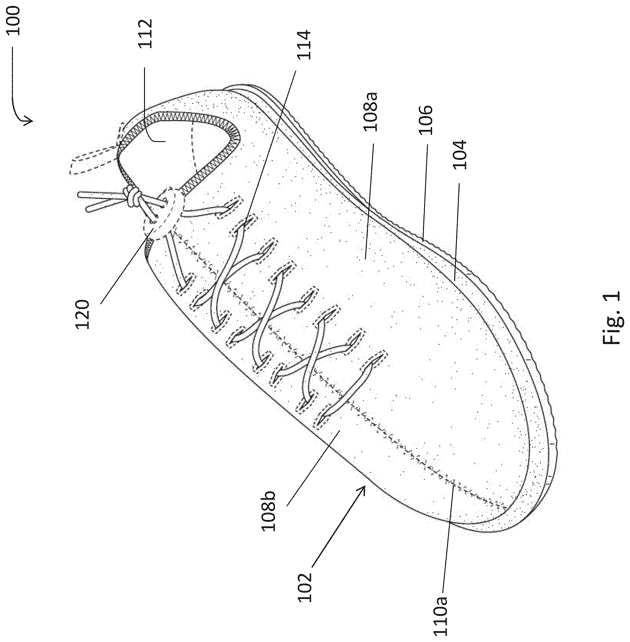
[0017] FIGS. 1-3 illustrate an embodiment of a slipper according to embodiments disclosed herein. As shown in these views, the slipper includes an upper 102, a footbed 104, and a bottom 106. In some embodiments, as will be described, the upper includes a lateral side 108a and a medial side 108b. In such embodiments, the lateral and medial sides 108a, 108b may be joined together via one or more seams. For example, a first seam 110a may be located in a front portion of the slipper (see FIGS. 1 and 3), and a second seam may be located in a rear or heel portion of the slipper (see FIG. 2). In some embodiments, the front seam is located in a central portion of the slipper, such as along a longitudinal axis of the slipper. As shown in these views, the front seam may be located on a first side of an opening 112 into which a user may insert his foot, with the second seam being located on a second, opposite side of the opening.
[0018] Although the upper is shown as having medial and lateral sides that are joined together, in other embodiments, the upper may be formed of a single, unitary piece. In other embodiments, the upper may be formed of three or more pieces that are attached, such as sewn, together.
[0019] In some embodiments the upper may include one or more eyelets 114 through which a lace 116 may be inserted for tightening the slipper. In some embodiments, the eyelets may include button holes formed in each of the lateral and medial sides of the upper. Although the upper is shown with 8 eyelets on each of the medial and lateral sides, the upper may have more or fewer eyelets. For example, the upper may have 2 or more eyelets on each of the medial and lateral sides. As will be further appreciated, the medial and lateral sides need not have the same number of eyelets. For example, the medial side may include 8 eyelets while the lateral side includes 6 eyelets.
[0020] In some embodiments, as illustrated in FIGS. 1 and 3, the slipper is arranged to be adjustable by the wearer. For example, the wearer may pull on the laces to move the eyelets closer to one another (see the arrow labeled X in FIG. 4). In some embodiments, as shown in FIG. 5, the wearer also may move a portion of the upper (see the arrow labeled Y) to insert his foot into the opening and/or to adjust the fit of the slipper on his foot prior to tightening the laces. In some embodiments, as shown in FIG. 4, when the wearer has tightened the laces, the user may tie a knot in the laces to maintain the slipper with the desired fit around the wearer's foot. In other embodiments, as shown in FIGS. 1 and 3, the slipper may include a clip 120 arranged to hold the tightened laces together, with the slipper being held in the desired fit. In some embodiments, the lace or cord may be made of an elastic material so as to maintain even tension around the foot without causing the wearer discomfort or specific points of irritation directly under the laces.
[0021] In some embodiments, when the slipper is in a tightened position, one or more portions of the upper may move over or under other portions of the upper. For example, as show in FIG. 3, in the tightened position, a portion of each of the lateral and medial sides of the upper slipper have been rolled over one another (e.g., near the eyelets).
[0022] In some embodiments, to remove the slipper from the wearer's foot, the wearer may untie the laces or release the clip to loosen the upper from around the wearer's foot. The wearer may then remove his foot from the opening in the slipper.
[0023] FIGS. 6-13 illustrate a method of manufacturing a slipper according to aspects of the present disclosure. First, as illustrated in FIG. 6-7, the medial and lateral sides of the upper may be assembled. As shown in FIG. 6, in some embodiments, to assemble the lateral side 108a of the slipper, a lateral outer layer 118 and a lateral inner layer 120 are aligned and attached to one another. In such embodiments, the shape and size of the inner layer may be the same as the shape and size of the outer layer. As shown in FIG. 7, in some embodiments, the inner and outer layers 118, 120 of the lateral side 108a of the upper may be stitched together (see seem 122) around a collar area 124 that may later form a portion of the opening into which the wearer may insert his feet.
[0024] As shown in FIG. 6, the outer layer 118 may include one or more eyelets 114 or button holes for receiving the laces, as previously described. In some embodiments, the inner layer may not include eyelets 114, however, the inner layer may include one or more eyelets in other embodiments.
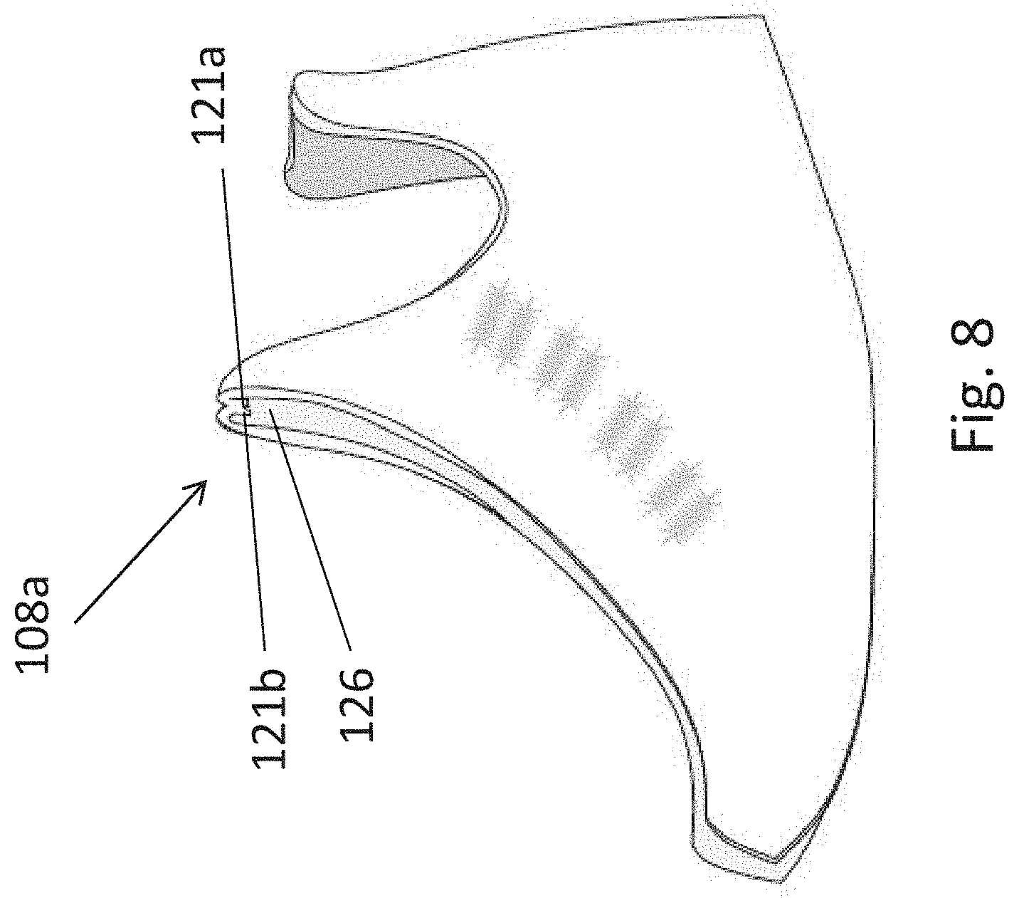
[0025] Next, the attached layers of the lateral side may be turned inside out, such as by moving the outer layer 118 about the collar region (see the arrow labeled Z in FIG. 7). As shown in FIG. 8, once the attached layers of the lateral side have been turned inside out, the unfished edges 121a, 121b of the outer and inner layers 118, 120 of the lateral side 108a of the slipper at the collar region 124 are no longer visible to the wearer. For example, the unfinished edges 121a, 121b of the outer and inner layers may be hidden in a pocket 126 formed between the inner and outer layers.
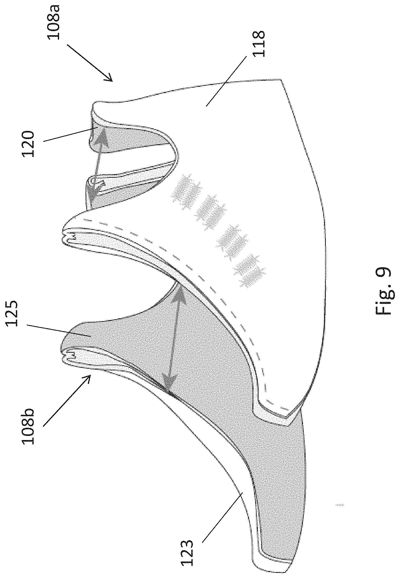
[0026] In some embodiments, the previous steps may be repeated to form the medial side of the upper. For example, inner 123 and outer 125 layers of the medial side of the upper (see FIG. 9) may be aligned and attached to one another at a collar region. Once attached, the inner and outer layers may be turned inside out such that the unfinished edges of the outer and inner layers of the medial side of the slipper at the collar region are no longer visible.
[0027] FIG. 9 illustrates the step in which the assembled lateral 108a and medial 108b sides of the upper 102 are aligned with one another other along a front center portion of the upper and a rear or heel portion of the upper. Once aligned, the lateral 108a and medial 108b sides of the upper may be attached to one another, such as via stitching. In some embodiments, a top stitch may be used to join the lateral and medial sides together, with the seams facing outwards. In some embodiments, a raw or unfinished edge of the lateral and/or medial sides may be visible along one or both of the seams. As shown in FIG. 10, the lateral and medial sides may be joined at a front seam 110a and at a rear seam. In some embodiments, the front seam is located in central portion of the front of the slipper. In some embodiments, the rear seam is located in a central region of the heel of the slipper.
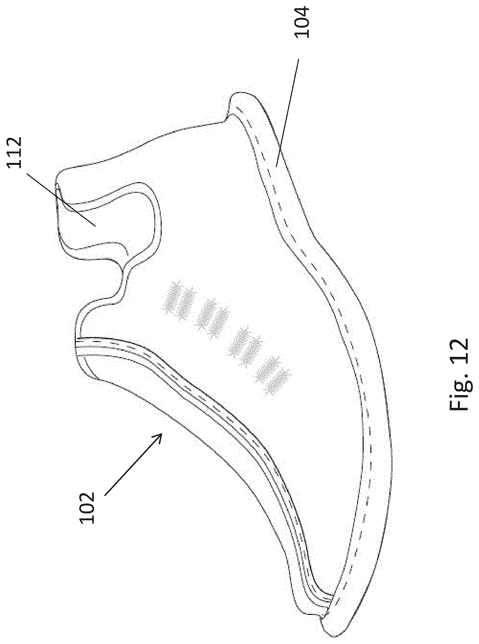
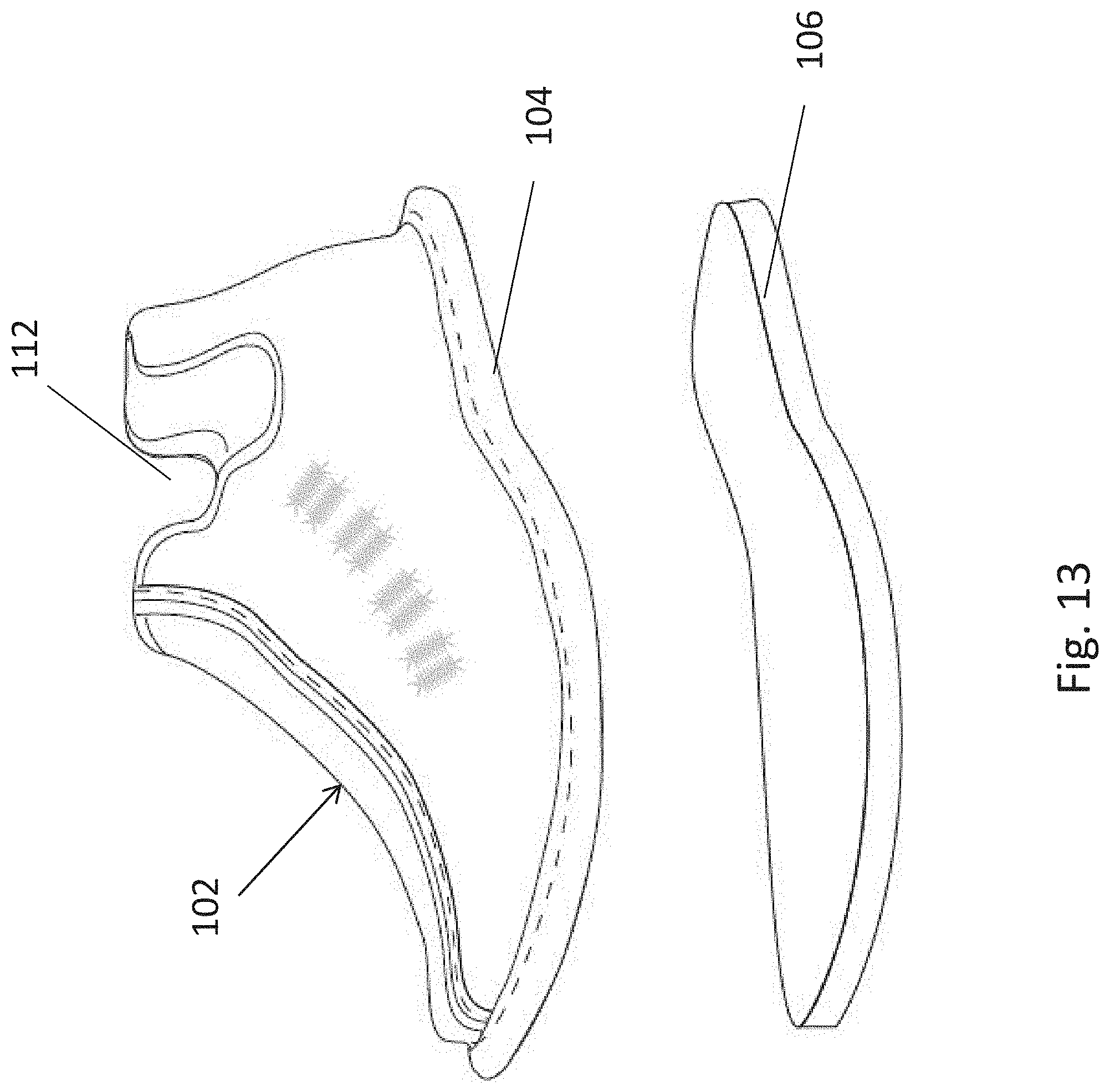
[0028] Next, as shown in FIG. 11, a footbed 104 may be attached to the upper. In some embodiments, the footbed is attachable to the upper via a binding that is positioned around an edge of the upper. In some embodiments, the footbed may be stitched to the upper. FIG. 12 illustrates the footbed secured to the upper, with the binding being visible.
[0029] Finally, as shown in FIG. 13, the bottom may be attached to upper and/or footbed. For example, the bottom may be stitched on to the upper and/or footbed (see the seam 128 in FIG. 14). FIG. 1 illustrates an example of an assembled slipper.
[0030] As will be appreciated, the slipper may be formed of any suitable material or combination of materials. In some embodiments, each upper, footbed, and bottom may be made of different materials. For example, in some embodiments, the upper may be formed of a fabric material, such as terry cloth or fleece, while the bottom is formed of an EVA foam. Other suitable materials may be used in other embodiments.
[0031] Although embodiments have been shown and described for making slippers, it will be appreciated that the present disclosure may be used to make other types of footwear, such as sneakers.
[0032] While the present teachings have been described in conjunction with various embodiments and examples, it is not intended that the present teachings be limited to such embodiments or examples. On the contrary, the present teachings encompass various alternatives, modifications, and equivalents, as will be appreciated by those of skill in the art. Accordingly, the foregoing description and drawings are by way of example only.
[0033] Various aspects of the present invention may be used alone, in combination, or in a variety of arrangements not specifically discussed in the embodiments described in the foregoing and is therefore not limited in its application to the details and arrangement of components set forth in the foregoing description or illustrated in the drawings. For example, aspects described in one embodiment may be combined in any manner with aspects described in other embodiments.
[0034] Also, the invention may be embodied as a method, of which an example has been provided. The acts performed as part of the method may be ordered in any suitable way. Accordingly, embodiments may be constructed in which acts are performed in an order different than illustrated, which may include performing some acts simultaneously, even though shown as sequential acts in illustrative embodiments.
[0035] Use of ordinal terms such as "first," "second," "third," etc., in the claims to modify a claim element does not by itself connote any priority, precedence, or order of one claim element over another or the temporal order in which acts of a method are performed, but are used merely as labels to distinguish one claim element having a certain name from another element having a same name (but for use of the ordinal term) to distinguish the claim elements.
[0036] Also, the phraseology and terminology used herein is for the purpose of description and should not be regarded as limiting. The use of "including," "comprising," "having," "containing," "involving," and variations thereof herein, is meant to encompass the items listed thereafter and equivalents thereof as well as additional items.
* * * * *
D00000
D00001
D00002
D00003
D00004
D00005
D00006
D00007
D00008
D00009
D00010
D00011
D00012
D00013

XML
uspto.report is an independent third-party trademark research tool that is not affiliated, endorsed, or sponsored by the United States Patent and Trademark Office (USPTO) or any other governmental organization. The information provided by uspto.report is based on publicly available data at the time of writing and is intended for informational purposes only.
While we strive to provide accurate and up-to-date information, we do not guarantee the accuracy, completeness, reliability, or suitability of the information displayed on this site. The use of this site is at your own risk. Any reliance you place on such information is therefore strictly at your own risk.
All official trademark data, including owner information, should be verified by visiting the official USPTO website at www.uspto.gov. This site is not intended to replace professional legal advice and should not be used as a substitute for consulting with a legal professional who is knowledgeable about trademark law.