Rounded Strain Wave Gear Flexspline Utilizing Bulk Metallic Glass-Based Materials and Methods of Manufacture Thereof
Hofmann; Douglas C. ; et al.
U.S. patent application number 16/802267 was filed with the patent office on 2020-09-03 for rounded strain wave gear flexspline utilizing bulk metallic glass-based materials and methods of manufacture thereof. This patent application is currently assigned to California Institute of Technology. The applicant listed for this patent is California Institute of Technology. Invention is credited to Robert P. Dillon, Douglas C. Hofmann, Scott N. Roberts.
| Application Number | 20200278017 16/802267 |
| Document ID | / |
| Family ID | 1000004753123 |
| Filed Date | 2020-09-03 |


View All Diagrams
| United States Patent Application | 20200278017 |
| Kind Code | A1 |
| Hofmann; Douglas C. ; et al. | September 3, 2020 |
Rounded Strain Wave Gear Flexspline Utilizing Bulk Metallic Glass-Based Materials and Methods of Manufacture Thereof
Abstract
Harmonic drives are used widely in robotics as a method for achieving high gear reductions and for driving force transmissions. The harmonic drive is made a three components: a wave generator, a flexspline, and a circular spline. Embodiments described flexsplines for a metal strain wave gearing. The cup of the flexspline is free from sharp edges and with a rounded bottom with a curvature maximized based on the geometry of the flexspline. Compared to a steel flexspline, implementations of flexsplines will have the same outer diameter, the same number of teeth and profile, the same input shaft/base, the same wall thickness near the teeth, but comprise a rounded bottom where the input shaft/base transitions to the straight wall of the flexspline, providing improved performance of BMG flexsplines by reducing low cycle fatigue failures due to stress concentrations.
| Inventors: | Hofmann; Douglas C.; (Altadena, CA) ; Dillon; Robert P.; (Costa Mesa, CA) ; Roberts; Scott N.; (Altadena, CA) | ||||||||||
| Applicant: |
|
||||||||||
|---|---|---|---|---|---|---|---|---|---|---|---|
| Assignee: | California Institute of
Technology Pasadena CA |
||||||||||
| Family ID: | 1000004753123 | ||||||||||
| Appl. No.: | 16/802267 | ||||||||||
| Filed: | February 26, 2020 |
Related U.S. Patent Documents
| Application Number | Filing Date | Patent Number | ||
|---|---|---|---|---|
| 62811798 | Feb 28, 2019 | |||
| Current U.S. Class: | 1/1 |
| Current CPC Class: | F16H 49/001 20130101; F16H 2049/003 20130101 |
| International Class: | F16H 49/00 20060101 F16H049/00 |
Goverment Interests
GOVERNMENT SPONSORED RESEARCH
[0002] This invention was made with government support under Grant Number 80NM0018D004, awarded by NASA (JPL). The government has certain rights in the invention.
Claims
1. A cup-type flexspline for a metal strain wave gear comprising, a base, and a vertical wall, wherein the vertical wall transitions through a curvature to the base, wherein an input shaft is disposed at the base; wherein the vertical wall is circular with an outer wall diameter, wherein the flexspline maintains circularity along the rotational axis of the vertical wall; wherein the maximum radius of curvature at the base of the cup is at least 10% of the diameter of the flexspline in accordance with the equation: Maximum radius of curvature = ( Diameter of outer wall of flexspline ) - ( Diameter of input shaft ) 2 ##EQU00003##
2. A cup-type flexspline for a metal strain wave gear of claim 1, wherein the radius of curvature is between about 15% to about 20% of the diameter of the flexspline.
3. A cup-type flexspline for a metal strain wave gear of claim 1, wherein the flexspline has a flush input base.
4. A cup-type flexspline for a metal strain wave gear of claim 1, wherein the flexspline has a hemispherical base curvature.
5. A cup-type flexspline for a metal strain wave gear of claim 1, wherein the flexspline has an elliptical base curvature.
6. A cup-type flexspline for a metal strain wave gear of claim 1, wherein the flexspline comprises a bulk metallic glass-based material.
7. A cup-type flexspline for a metal strain wave gear of claim 6, wherein the bulk metallic glass-based material is a bulk metallic glass.
8. A cup-type flexspline for a metal strain wave gear of claim 6, wherein the bulk metallic glass-based material is a bulk metallic glass matrix composite.
9. A cup-type flexspline for a metal strain wave gear of claim 6, wherein the flexspline has a fatigue life of at least 10% longer than a flexspline with the radius of curvature between about 1% to about 2% when run at the same torque.
10. A cup-type flexspline for a metal strain wave gear of claim 6, wherein the flexspline is formed using a net shape process.
11. A cup-type flexspline for a metal strain wave gear of claim 6, wherein the flexspline forming technique is one of: an injection molding technique; a die casting technique; a 3D printing technique; a thermoplastic forming technique; a blow molding technique; a discharge forming technique; a metal injection molding technique; a pressing with powder technique; a suction casting technique; and a forming from sheet metal technique.
12. A cup-type flexspline for a metal strain wave gear of claim 1, wherein the flexspline comprises a brittle material, wherein the brittle material has a fracture toughness less than about 50 MPa m.sup.1/2.
13. A cup-type flexspline for a metal strain wave gear of claim 1, wherein the flexspline comprises a metal alloy, wherein the metal alloy has less than about 10% ductility in a tension test.
14. A cup-type flexspline for a metal strain wave gear of claim 1, wherein the flexspline comprises at least one of tool steel, nanocrystalline metals, nanograined metals, ceramics, and metal matrix composites.
15. A cup-type flexspline for a metal strain wave gear of claim 1, wherein the flexspline comprises a laminate of at least two materials.
16. A cup-type flexspline for a metal strain wave gear of claim 15, wherein the laminate material comprises at least one of metal, and carbon fiber with a metal coating.
Description
CROSS-REFERENCE TO RELATED APPLICATIONS
[0001] The current application claims the benefit of and priority under 35 U.S.C. .sctn. 119(e) to U.S. Provisional Patent Application No. 62/811,798 entitled "Design for a Rounded Strain Wave Gear Flexspline Utilizing Bulk Metallic Glass-Based Materials" filed Feb. 28, 2019. The disclosure of U.S. Provisional Patent Application No. 62/811,798 is hereby incorporated by reference in its entirety for all purposes.
FIELD OF THE INVENTION
[0003] The present invention generally relates to apparatus and systems for a rounded strain wave gear flexspline utilizing bulk metallic glass-based materials; and more particularly to a change of the flexspline geometry that reduces low cycle fatigue failure.
BACKGROUND OF THE INVENTION
[0004] Harmonic drives (HDs) are used widely in robotics as a method for achieving high gear reductions and for driving force transmissions. HDs were developed to take advantage of the elastic dynamics of metals, particularly the expansion of a metal ring to engage gear teeth without exceeding the elastic limit of the ring, which would cause permanent (i.e. plastic) deformation. The HD is made of three components: a wave generator, a flexspline (a.k.a. an inner race), and a circular spline (a.k.a. an outer race) (FIG. 1). The wave generator is an elliptical cam with small ball-bearings built into the outer circumference and is usually attached to the input shaft. The flexspline, is a thin metal cup with external gear teeth and contains a diaphragm at the bottom of the cup for connecting to an output shaft. The circular spline is a steel ring with internal teeth and is usually fixed to a casing. The circular spline has two more teeth than the flexspline and the diameter of the circular spline is slightly larger than the flexspline such that if they were put together without the wave generator, they would be concentric and their teeth wouldn't touch.
[0005] In operation, the flexspline is deflected by the motion of the elliptical wave generator, which forces the teeth at the major axis of the ellipse to engage with the circular spline (while the teeth at the minor axis are completely disengaged). When the wave generator completes 180 degrees of motion, the flexspline has moved by one tooth relative to the circular spline. The movement of the flexspline is the output power.
[0006] HDs have many characteristics that make their use critical in robotics applications. They have high-speed reduction ratios of 1/30 to 1/320, which provides high efficiency gearing without using complex mechanisms. HDs operate with nearly zero backlash and have extremely high precision. They have small numbers of components and assemble easily and they can generally be small-sized and lightweight. HDs have high torque capacity due to the use of fatigue resistance steel in the flexspline and they have high efficiency.
BRIEF SUMMARY OF THE INVENTION
[0007] Methods and systems for designing low cost wave generator for metal strain wave gearing are illustrated.
[0008] Many embodiments are directed to a cup-type flexspline for a metal strain wave gear comprising, a base, and a vertical wall, where the vertical wall transitions through a curvature to the base, where an input shaft is disposed at the base; wherein the vertical wall is circular with an outer wall diameter, where the flexspline maintains circularity along the rotational axis of the vertical wall; where the maximum radius of curvature at the base of the cup is at least 10% of the diameter of the flexspline in accordance with the equation:
Maximum radius of curvature = ( Diameter of outer wall of flexspline ) - ( Diameter of input shaft ) 2 ##EQU00001##
[0009] In many other embodiments, the radius of curvature is between about 15% to about 20% of the diameter of the flexspline.
[0010] In still many other embodiments, the flexspline has a flush input base.
[0011] In yet many other embodiments, the flexspline has a hemispherical base curvature.
[0012] In still yet many other embodiments, the flexspline has an elliptical base curvature.
[0013] In still yet many other embodiments, the flexspline comprises a bulk metallic glass-based material.
[0014] In further embodiments, the bulk metallic glass-based material is a bulk metallic glass.
[0015] In yet many embodiments, the bulk metallic glass-based material is a bulk metallic glass matrix composite.
[0016] In still yet many other embodiments, the flexspline has a fatigue life of at least 10% longer than a flexspline with the radius of curvature between about 1% to about 2% when run at the same torque.
[0017] In still yet other embodiments, the flexspline is formed using a net shape process.
[0018] In still yet many other embodiments, the flexspline forming technique is one of: an injection molding technique; a die casting technique; a 3D printing technique; a thermoplastic forming technique; a blow molding technique; a discharge forming technique; a metal injection molding technique; a pressing with powder technique; a suction casting technique; and a forming from sheet metal technique.
[0019] In still yet many other embodiments, the flexspline comprises a brittle material, wherein the brittle material has a fracture toughness less than about 50 MPa m.sup.1/2.
[0020] In still yet many other embodiments, the flexspline comprises a metal alloy, wherein the metal alloy has less than about 10% ductility in a tension test.
[0021] In still yet many other embodiments, the flexspline comprises at least one of tool steel, nanocrystalline metals, nanograined metals, ceramics, and metal matrix composites.
[0022] In still yet many other embodiments, the flexspline comprises a laminate of at least two materials.
[0023] In still yet many other embodiments, the laminate material comprises at least one of metal, and carbon fiber with a metal coating.
[0024] Additional embodiments and features are set forth in part in the description that follows, and in part will become apparent to those skilled in the art upon examination of the specification or may be learned by the practice of the disclosure. A further understanding of the nature and advantages of the present disclosure may be realized by reference to the remaining portions of the specification and the drawings, which forms a part of this disclosure.
BRIEF DESCRIPTION OF THE DRAWINGS
[0025] The description will be more fully understood with reference to the following figures, which are presented as exemplary embodiments of the invention and should not be construed as a complete recitation of the scope of the invention, wherein:
[0026] FIG. 1 illustrates a strain wave in accordance with the prior art.
[0027] FIG. 2 conceptually illustrates a flexspline geometry configured to reduce low cycle fatigue failure when the flexspline is made from a brittle metal in accordance with embodiments.
[0028] FIGS. 3A-3B illustrate flexsplines manufactured from solid billets or castings using conventional machining processes, such as lathing, milling, or grinding in accordance with the prior art.
[0029] FIG. 4 illustrates three common sizes of strain wave gear flexsplines made from machined steel, where the flexspline has a flat input that interfaces with a component to transmit torque in accordance with the prior art.
[0030] FIG. 5 illustrates the cross-section of a machined steel size CSF-20 flexspline showing a radius of curvature in accordance with the prior art.
[0031] FIGS. 6A-6D illustrate a stress concentration is created when replicating a machined steel flexspline during injection molding of bulk metallic glass (BMG) in accordance with embodiments.
[0032] FIG. 7 illustrates injection molded bulk metallic glass flexsplines, where these parts are cast to replicate the shape of the machined steel versions, which are designed to maximize torque due to the straight walls in accordance with embodiments.
[0033] FIGS. 8A-8C illustrate a blow molding process that thermoplastically forms BMGs into flexsplines, where replicating the steel version creates sharp edges in accordance with embodiments.
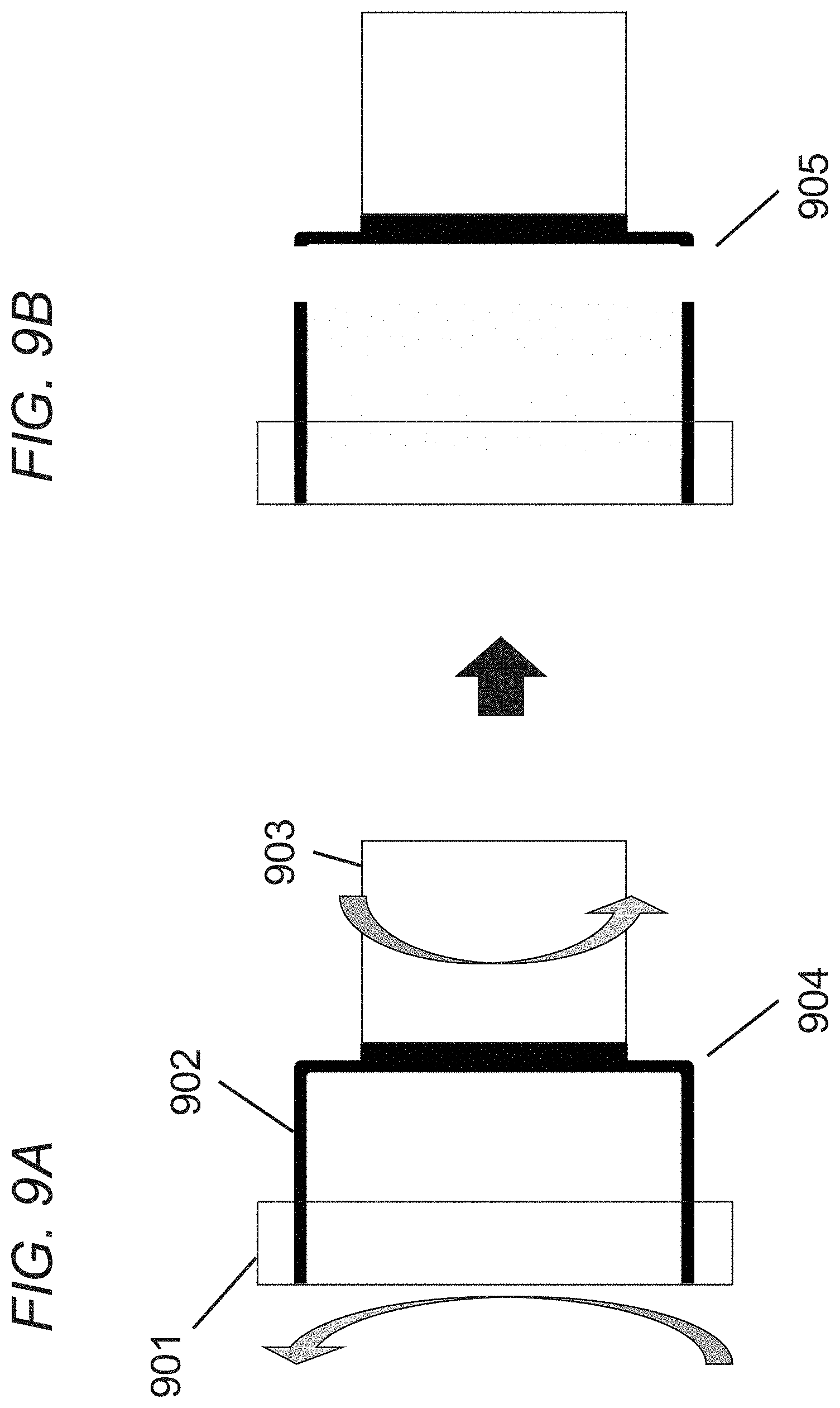
[0034] FIGS. 9A-9B illustrate a BMG flexspline loaded and the subsequent low cycle fatigue failure due to the low toughness of the BMG in accordance with embodiments.
[0035] FIG. 10 illustrates a BMG flexspline connected to an input shaft and then to an outer spline to drive torque, where sharp corners are removed in accordance with embodiments.
[0036] FIG. 11 illustrates a low cycle fatigue crack in a CSF-20-50 BMG flexspline after approximately 20,000 cycles at 30 Nm of torque, where the crack originates from the stress concentration at a small radius of curvature in accordance with embodiments.
[0037] FIG. 12 illustrates a BMG flexspline sheared off under load at the location of a stress concentration in accordance with embodiments.
[0038] FIG. 13 illustrates the maximum possible radius of curvature at the edge of the cup based on the fixed diameters of the flexspline wall and the input base in accordance with embodiments.
[0039] FIGS. 14A-14D illustrate stress concentration reduction by rounding the bottom of the cup in accordance with embodiments.
[0040] FIGS. 15A-15D illustrate a modified blow molding process that allows a curve to form at the edges of the flexspline in accordance with embodiments.
[0041] FIG. 16 illustrates a flexspline geometry that has a hemispherical base with a protruding flat input base in accordance with embodiments.
[0042] FIG. 17 illustrates a flexspline geometry that has an elliptical radius of curvature in accordance with embodiments.
[0043] FIG. 18 illustrates a flexspline geometry that has an input base flush to the flexspline, eliminating another sharp stress concentration in accordance with embodiments.
[0044] FIG. 19 illustrates a flexspline geometry that has two different spherical radii of curvature that make up the rounded corners of the flexspline in accordance with embodiments.
DETAILED DESCRIPTION OF THE INVENTION
[0045] Turning now to the drawings, cup-type flexsplines for metal strain wave gears, and systems and methods for their design and manufacture, are described. In many embodiments, the cup-type flexspline has a base and a vertical wall, where the vertical wall transitions through a curvature to the base. An input shaft locates at the base of the flexspline and has a diameter. The vertical wall is in a circular shape with an outer wall diameter, and the flexspline maintains circularity along the rotational axis of the vertical wall. Many embodiments of the invention describe a flexspline that the cup of the flexspline is free from sharp edges and with a rounded bottom with curvature maximized based on the geometry of the flexspline. Many embodiments describe the maximum radius of curvature at the base of the cup is at least 10% of the diameter of the flexspline. Many other embodiments highlight that the radius of curvature is between about 15% to about 20% of the diameter of the flexspline. Flexsplines according to such embodiments demonstrate improved fatigue life of at least about 10% over designs with sharp angles between the base and the wall when run at the same torque.
[0046] In many embodiments, the flexspline has a hemispherical base curvature. In some other embodiments, the flexspline has an elliptical base curvature. In some embodiments, the flexspline has a flush input base. In some other embodiments, the flexspline has two different spherical radii of curvature. Many embodiments describe that the flexspline is made of bulk metallic glass-based material. Many embodiments reveal that the bulk metallic glass-based material can be made from near or net-shaped processes, such as injection molding, die casting, 3D printing, thermoplastic forming, blow molding, discharge forming, metal injection molding, pressing with powder, suction casting, forming from sheet metal or a variety of other processes whereby feedstock is formed into the flexspline in a single step without significant machining. In many embodiments, the flexspline is made from a brittle material with a fracture toughness of less than about 50 MPa m.sup.1/2. In some other embodiments, the flexspline is made from a metal alloy with less than about 10% ductility in a tension test. In some other embodiments, the flexspline is made from tool steel, nanocrystalline metals, nanograined metals, ceramics, or metal matrix composites.
[0047] Harmonic drives are one of the driving factors in the early formulation of spacecraft design because they limit the size of the spacecraft. Harmonic drives are also used very heavily on Jet Propulsion Lab rovers, including many that were integrated into the Mars Exploration Rovers (MER). Developing low cost harmonic drives or high performance drives is game-changing for future NASA missions and for terrestrial robotics.
[0048] Harmonic drives were developed to take advantage of the elastic dynamics of metals, particularly the expansion of a metal ring to engage gear teeth without exceeding the elastic limit of the ring, which would cause permanent (i.e. plastic) deformation. The harmonic drive is made of three components: a wave generator, a flexspline (a.k.a. an inner race), and a circular spline (a.k.a. an outer race).
[0049] FIG. 1 illustrates an exploded view of a typical strain wave gear that can be fabricated from BMG-based materials in accordance with embodiments of the invention. In particular, the strain wave gear 100 includes a wave generator 102, a flexspline 108, and a circular spline 112. The illustrated wave generator 102 includes a wave generator plug 104 and a ball bearing 106. Importantly, the wave generator plug 104 is elliptical in shape, and is disposed within the ball bearing 106 so that the ball bearing 106 conforms to the elliptical shape. In this arrangement, the outer race of the ball bearing 106 can rotate relative to the wave generator plug 104.
[0050] In the illustrated embodiment, the flexspline 108 is depicted as being in the shape of a cup; notably, the outer rim of the cup includes a set of gear teeth 110. In the illustration, the flexspline is fitted over the ball bearing, such that the outer rim of the flexspline conforms to the aforementioned elliptical shape. Note that in this arrangement, the ball bearing allows the flexspline to rotate relative to the wave generator plug. The circular spline, 112 is in the shape of a ring; importantly, the inner perimeter of the ring includes a set of gear teeth. Normally, there are more gear teeth on the circular spline 114 than on the flexspline 110. In many instances there are two more gear teeth on the circular spline 112 than on the flexspline 108. Typically, the flexspline 108 is fitted within the circular spline 112 such that the gear teeth of the flexspline 110 engage the gear teeth of the circular spline 114. Notably, because the gear teeth of the flexspline 110 conform to an elliptical shape, only the gear teeth proximate the major axis of the elliptical shape engage the gear teeth of the circular spline 114 in the usual case. Conversely, the gear teeth of the flex spline 110 that are proximate the minor axis of the elliptical shape are disengaged from the gear teeth of the circular spline 114. In many instances, 30% of the gear teeth of the flexspline 110 are engaged with the gear teeth of the circular spline 114. With this arrangement, the wave generator plug 104 can rotate in a first direction about the central axis of the elliptical shape, and thereby cause the flexspline 108 to rotate in a second opposite direction and at a different rate of rotation (generally slower) about the central axis of the elliptical shape. This can be achieved as the flexspline 108 is made of a flexible material that can accommodate the deflections that may result from the rotation of the wave generator plug 104.
[0051] The primary method by which strain wave gear flexsplines are manufactured is through the machining of steel. FIGS. 3A-3B illustrate methods where flexsplines are manufactured from solid billets or castings using conventional machining processes, such as lathing, milling, or grinding. A lathe 301 rotates a flexspline about an axis of rotation to perform cutting by the cutting tool 302. A straight edge 303 of the flexspline is shown in FIG. 3B. In this method, machining a large radius of curvature is challenging compared to a straight edge.
[0052] The vast majority of current commercial flexsplines are made of steel, which is known for its combination of high toughness and wear resistance. Typical cup-type flexsplines are made with a vertical wall that transitions through a 90 degree angle to a base where an input shaft is located. FIG. 4 depicts three common sizes of strain wave gear flexspline: 401 is CSF-32 flexspline, 402 is the CSF-20 flexspline, and 403 is CSF-8 flexspline. Each flexspline is made from machined steel, and has a radius of curvature 404 between the base of the cup 405 and the wall 406 of about 1% to about 2% of the diameter of the wall. The flexspline has a flat input that interfaces with a component to transmit torque. The base 405 is preferably to be flat to make a mating interface. Due to the high toughness of steel, the small radius of curvature 404 is sufficient to prevent fracture.
[0053] The torque that the flexspline can support is a function of the size of the flexspline cup, its length and the number of teeth on the flexspline outer wall. Due to the very high toughness of steel and the limitations of conventional machining, a very small radius of curvature is added to the bottom of the flexspline cup, typically about 1% to about 2% of the diameter of the flexspline. FIG. 5 shows the cross-section of a typical machined steel size CSF-20 flexspline with a radius of curvature 501 of about 1 millimeter, which is about 1% to 2% of the diameter of the flexspline. Machining larger radii of curvature is more difficult due to the necessity of keeping the flexspline perfectly symmetric along its rotational axes. Due to the high toughness of steel, the small radius of curvature is not a normal location of failure of the flexspline, which normally fails due to buckling of the flexspline wall or the degradation of the flexspline teeth. In operation, a steel flexspline is rarely expected to crack or fail due to a stress concentration.
[0054] Despite the high performance of steel in the flexspline, it is expensive to manufacture due to the difficulty with machining steel, the high-tolerance features, and the very thin wall. Bulk metallic glasses (BMGs) have been demonstrated to be ideal candidates for flexsplines because they can be manufactured using near or net-shaped processes, such as injection molding, die casting, thermoplastic forming, metal injection molding or a variety of other processes whereby feedstock is formed into the flexspline in a single step without significant machining. (See e.g., U.S. Pat. No. 9,328,813 B2 to Hofmann et al., U.S. Pat. No. 10,151,377 B2 to Hofmann et al., U.S. patent application Ser. No. 15/918,831 to Hofmann et al., U.S. patent application Ser. No. 62/811,765 to Hofmann et al.; the disclosures of which are hereby incorporated by reference.)
[0055] BMG-based material flexsplines have been manufactured to mimic the shape of the steel flexsplines, which contain several locations of stress concentrations. As an example, FIGS. 6A-6D illustrate an injection molding technique that can be implemented to form a flexspline of a strain wave gear in accordance with embodiments of the invention. In particular, FIG. 6A depicts that a molten BMG-based material 601 that has been heated to a molten state and is thereby ready to be inserted into a mold 602. The mold 602 helps define the shape of the flexspline to be formed. FIG. 6B depicts that the molten BMG-based material 601 is pressed into the mold 602. FIG. 6C depicts that the mold 602 is released after the BMG-based material has cooled. FIG. 6D depicts that any excess flash 603 is removed. Thus, it is depicted that a strain wave gear component is fabricated using direct casting techniques in conjunction with a BMG-based material in accordance with embodiments of the invention. Note that the straight edge of the flexspline 604 from replicating the steel flexspline models creates stress concentration. FIG. 7 shows the BMG-based material flexsplines made with injection molding technique. The flexsplines have been cast to replicate the shape of the machined steel versions, which are designed to maximize torque due to the straight walls.
[0056] FIGS. 8A-8C illustrate the forming of a flexspline using blow molding techniques. In particular, FIG. 8A depicts that a BMG-based material 801 is placed within a mold 802. FIG. 8B depicts that the BMG-based material 801 is exposed to pressurized gas or liquid that forces the BMG-based material to conform to the shape of the mold 802. Typically, a pressurized inert gas is used. The BMG-based material 801 is usually heated so that it is sufficiently pliable and can be influenced by the pressurized gas or liquid. Again, any suitable heating technique can be implemented in accordance with embodiments of the invention. FIG. 8C depicts that due to the force of the pressurized gas or liquid, the BMG-based material conforms to the shape of the mold 802. Replicating the steel flexspline creates sharp edges 803 in the BMG-based flexspline.
[0057] However, unlike steel, BMG-based materials are known for having much lower fracture toughness and fatigue life. In fact, BMG flexsplines tend to fail via cracking or shearing at much lower number of cycles than their steel counterparts. BMG-based materials are typically associated with fracture toughness less than about 50 MPa m.sup.1/2 whereas steel is normally greater than about 100 MPa m.sup.1/2. Fatigue strengths of steel are typically greater than about 20% of their yield strength whereas BMG-based materials normally fail at less than about 10% of their yield strengths at about 107 cycles.
[0058] As an example, FIGS. 9A-9B illustrate schematically a BMG flexspline fatigue failure due to the low toughness of the BMG-based material. FIG. 9A depicts the outer spline 901 rotates counter clockwise along the axis of rotation of the flexspline, while the input shaft 903 rotates clockwise along the axis of rotation. The brittle BMG-based material flexspline 902 is loaded. The straight edge of the flexspline creates the stress concentration 904. FIG. 9B depicts the low cycle fatigue failure 905 due to the low toughness of the BMG-based material. For brittle materials, like BMG, stress concentration creates premature failure under loading.
[0059] FIG. 10 illustrates the stress concentration in a BMG-based material flexspline. A BMG flexspline 1001 is connected to an input shaft 1003, and then to an outer spline 1004 to drive torque. Due to the brittle nature of the BMG, sharp corners 1002 are locations of failure. FIG. 11 shows a fatigue crack in a CSF-20-50 BMG flexspline. The low cycle fatigue crack 1101 appears in the flexspline after approximately 20,000 cycles at 30 Nm of torque. The crack originates from the stress concentration at the small radius of curvature 1102. FIG. 12 shows a BMG flexspline that has been sheared off under load at the location of a stress concentration. These types of failure do not occur in steel flexsplines.
[0060] Although BMGs can be cast for potentially much lower cost than steel, their brittle nature makes them perform worse, despite their higher strength (about 2000 MPa compared to about 500 MPa for steel), higher wear resistance, lower elastic modulus (about 90 GPa compared to about 215 GPa for steel), higher elasticity (about 2% compared to about 0.1% for steel), and corrosion resistance. Improving the design of the flexspline could simultaneously improve performance and reduce the difficulty with net-shaped casting.
Embodiments Implementing Rounded Bulk Metallic Glass-Based Materials Flexsplines
[0061] Many embodiments of the invention describe a strain wave gear flexspline where the cup of the flexspline is free from sharp edges and with a rounded bottom with curvature maximized based on the geometry of the flexspline (FIG. 2). Compared to a steel flexspline, the new design will have the same outer diameter, the same number of teeth and profile, the length of the flexspline, the same size and shape of the input shaft/base, the same wall thickness near the teeth, but will have a rounded bottom where the input shaft/base transitions to the straight wall of the flexspline. Embodiments demonstrate that the large radius of curvature of the flexspline improves the performance of a BMG-based material flexspline by reducing low cycle fatigue failures due to stress concentrations.
[0062] Many embodiments of the invention refer to bulk metallic glass (BMG) as an alloy which can be quenched into a vitreous state at a relatively large casting thickness (generally over 1 mm). BMGs can also be referred to as amorphous metals (AMs) and their composites as amorphous metal composites (AMCs). Many other embodiments of the invention refer to in-situ composite or bulk metallic glass matrix composite (BMGMC) as an alloy which, upon rapid cooling (cooling rate from about 1K/s to about 1000 K/s), chemically partitions into two or more phases, one being an amorphous matrix and the other(s) being crystalline inclusions. The term "bulk metallic glass-based materials" (BMG-based materials) includes both BMGs and BMGMCs.
[0063] Given that shearing and cracking is not a normal mode of failure for steel, changing the radius of curvature of the flexspline cup as described in many of the embodiments is not a conventional approach. Moreover, almost all flexsplines are machined from steel and small radii of curvatures are far easier to machine than large ones, especially when circularity must be maintained to high tolerances. In addition, flexspline cups having small radii of curvature maximize the operating torque of the strain wave gear. Nevertheless, embodiments implementing rounded edges are shown to improve the fatigue life of a BMG flexspline as compared to a straight wall cup. Moreover, the rounded shape reduces the net shaped manufacturing, as inserts normally used for casting around release much easier from the mold when they are round, as opposed to sharp. Accordingly, embodiments implementing brittle materials, like BMGs and others, simultaneously improve castability and fatigue life by increasing the curvature of the flexspline cup.
[0064] Rounded flexsplines according to embodiments decrease the performance of the strain wave gears, because rounded corners do not take as much load as straight walls. The performance of rounded flexsplines is compensated by the use of brittle materials in the flexsplines, which would otherwise crack in straight wall structures. In some embodiments, the brittle materials provide better performance in rounded flexsplines. In some other embodiments, the brittle materials are easier to manufacture. BMGs, according to such embodiments, can be cast into the flexsplines, which lowers the manufacturing cost of flexsplines.
[0065] Many embodiments of the invention remove stress concentrations at the base of the flexspline by adding a large radius of curvature to the base of the cup. Many embodiments increase the radius of curvature at the base of the flexspline cup from about 1% to about 2% of the flexspline diameter to at least 10% of the diameter of a standard flexspline while maintaining circularity along the rotational axis. Many other embodiments implement configurations that reduce other sharp edges in the apparatus. In various embodiments, cup-type flexsplines have a maximum radius of curvature of about 15% to about 20% based on the ratio of the input base diameter to the flexspline diameter. In many such embodiments, the maximum radius of curvature can be calculated with Equation 1:
Maximum radius of curvature = ( Diameter of outer wall of flexspline ) - ( Diameter of input shaft ) 2 ##EQU00002##
[0066] FIG. 13 illustrates a cup-type flexspline with a rounded edge according to many embodiments. Based on the fixed diameter of the flexspline wall and the input base, the maximum possible radius of curvature 1301 at the edge of the cup is 8 millimeter for a size CFS-20 flexspline. Without changing the diameter of the flexspline 1302 or the diameter of the input base 1303, the BMG flexspline can support a radius of curvature between about 15% to about 20% of the diameter of the flexspline. As a comparison, a conventional steel cup-type CFS-20 flexspline as depicted in FIG. 5 has a radius of curvature 501 of about 1 millimeter, which is about 1% to about 2% of the flexspline diameter.
[0067] Table 1 lists measurements of the diameter of the flexspline, the diameter of the input shaft/base, the approximate radius of curvature of the machined steel, the maximum radius of curvature possible and the maximum radius of curvature as a percentage of the diameter for three standard sizes of flexsplines. Overall, the radius of curvature of the machined steel is about 1% to about 2% of the diameter of the flexspline. By contrast, embodiments implement radius of curvature between about 15% to about 20% of the flexspline diameter, based on standard sizes. Embodiments demonstrate that the larger curvatures decrease the possible torque on the strain wave gear but reduces the stress concentrations of the BMG, resulting in longer life. Moreover, the rounded shape is easier to cast through near or net-shaped processes, such an injection molding, die casting, blow molding or metal injection molding.
TABLE-US-00001 TABLE 1 Maximum Diameter Diameter Machined Maximum Radius of of of Radius of Radius of Curvature Gear input shaft flexspline Curvature Curvature as % of size (mm) (mm) (mm) (mm) Diameter CSF-8 12.25 20 0.25 3.875 19% CSF-20 48 32 1 8 17% CSF-32 81 52 2 14.5 18%
[0068] In various embodiments, rounded edge BMG-based material flexsplines are manufactured with direct casting techniques in accordance with embodiments of the invention. Rounded edges are easier to cast than sharp edges. As an example, FIGS. 14A-14D illustrate a modified injection molding process that can be implemented to form a round edge flexspline in accordance with embodiments of the invention. In particular, FIG. 14A depicts a molten BMG-based material 1402 that has been heated to a molten state and is thereby ready to be inserted into a mold 1403. The mold 1403 helps define the shape of the flexspline to be formed to have rounded edges 1401. FIG. 14B depicts that the molten BMG-based material 1402 is pressed into the rounded edge 1401 mold 1403. FIG. 14C depicts that the mold 1403 is released after the BMG-based material has cooled. FIG. 14D depicts that any excess flash 1404 is removed. Note that the rounded edge of the cup of the flexspline 1401 reduces the stress concentration while simultaneously reduces the difficulty with manufacturing.
[0069] FIGS. 15A-15D illustrate the forming a rounded flexspline using blow molding techniques. In particular, FIG. 15A depicts that a BMG-based material 1501 is placed within a mold 1502 with rounded edges 1503. FIG. 15B depicts that the BMG-based material 1501 is exposed to pressurized gas or liquid that forces the BMG-based material to conform to the shape of the mold 1502. Typically, a pressurized inert gas is used. The BMG-based material 1501 is usually heated so that it is sufficiently pliable and can be influenced by the pressurized gas or liquid. Again, any suitable heating technique can be implemented in accordance with embodiments of the invention. FIG. 15C depicts that due to the force of the pressurized gas or liquid, the BMG-based material conforms to the shape of the mold 1502 with rounded edges 1503. The modified blow molding process allows a curve 1503 to form at the edges of the flexspline. FIG. 15D shows a prototype blow molded flexspline showing the natural tendency to form a hemisphere when expanding. This shape has the largest radius of curvature possible for the given diameter and thus the lowest stress concentration.
[0070] Many embodiments describe the flexspline is made at least in part of a bulk metallic glass-based material that has been manufactured into a near or net-shaped flexspline. The fatigue life of the flexspline is improved by at least 10% when run at the same torque as a flexspline made from the same material but with a standard flexspline design created for steel. Many embodiments describe that the BMG can be injection molded, die cast, 3D printed, thermoplastically formed, blow molded, discharge formed, metal injection molded, pressed with powder, suction cast, or formed from sheet metal. In other embodiments, the flexspline has an elliptical base curvature. Many other embodiments describe that the cracking during operation of the flexspline can be suppressed compared to a similar cup with a radius of curvature of about 1% to about 2% of the flexspline diameter.
[0071] Many other embodiments describe a flexspline of a cup-type strain wave gear that the radius of curvature at the base of the cup is at least 10% of the diameter of the flexspline. In some embodiments, the flexspline is made from a brittle material with a fracture toughness of less than 50 MPa m.sup.1/2. In some other embodiments, the flexspline is made from a metal alloy with less than 10% ductility in a tension test. In some other embodiments, the flexspline is made from tool steel, nanocrystalline or nanograined metals, ceramics, metal matrix composites.
Embodiments Implementing BMG-Based Material Flexsplines With A Spherical Radius Of Curvature
[0072] To accommodate BMG properties and manufacturing, many embodiments implement flexspline cups with features having reduced sharp edges. FIG. 16 illustrates embodiments where the BMG-based material flexspline has a hemispherical base with a protruding flat input base. In such embodiments, the flexspline has a wall 1605 with a diameter, an input base 1602 with a diameter, and a hemispherical base 1604. More particularly, the flexspline has a flat input base 1602 to connect to the input shaft. The radius of curvature of the hemisphere, according to such embodiments, depends on the diameter of the flexspline and the diameter of the input shaft. Many embodiments describe a radius of curvature of at least 10% of the diameter of the flexspline. Many other embodiments include the flexspline has a spherical radius of curvature. In some embodiments, the rounded base of the flexspline has axial symmetry around the rotational axis of the flexspline. Many other embodiments describe increasing the wall thickness to decrease stress concentrators. In many such embodiments, the diameter at the teeth 1601 of the flexspline and the thickness of the wall near the teeth do not change from the standard flexspline such that the flexspline will fit into a standard outer spline and wave generator. In many embodiments, the BMG flexspline can be used with a standard outer spline and wave generator based on the required size. However, the fatigue life and the manufacturing will be greatly enhanced through the rounding of the base.
Embodiments Implementing BMG-Based Material Flexsplines With An Elliptical Radius Of Curvature
[0073] Many other embodiments describe another design of the flexspline cup base that does not maintain the standard input base sizes and shapes. FIG. 17 illustrates a BMG-based material flexspline, according to embodiments, having a hemispherical base with a protruding flat input base. In such embodiments, the flexspline has a wall 1705 with a diameter, an input base 1702 with a diameter, and a hemispherical base 1704. The flexspline has a flat input base 1702 to connect to the input shaft. The radius of curvature of the rounded edge depends on the diameter of the flexspline and the diameter of the input shaft. Many embodiments describe the radius of curvature is at least 10% of the diameter of the flexspline. Many other embodiments include the flexspline has an elliptical radius of curvature. In some embodiments, the rounded base of the flexspline has axial symmetry around the rotational axis of the flexspline. In many such embodiments, the diameter at the teeth 1701 of the flexspline and the thickness of the wall near the teeth do not change from the standard flexspline such that the flexspline fits into a standard outer spline and wave generator. In many embodiments, the BMG flexspline can be used with a standard outer spline and wave generator based on the required size. However, the fatigue life and the manufacturing will be greatly enhanced through the rounding of the base.
Embodiments Implementing BMG-Based Material Flexsplines With A Flush Input Base
[0074] Many other embodiments describe embodiments including a flush input base such that when the flexspline is cast from BMG, it has an improved fatigue life of at least 10% over a BMG with a steel design when run at the same torque. FIG. 18 illustrates embodiments of a BMG-based material flexspline with a flush input base. The flexspline has a wall 1805 with a diameter, an input base 1802 with a diameter, and a hemispherical base 1804. The input shaft or base 1802 of the flexspline cup where connections are made is flush with the flexspline, to eliminate sharp stress concentration. The flush input base 1802 connects to the input shaft. The radius of curvature depends on the diameter of the flexspline and the diameter of the input shaft. Many embodiments describe the radius of curvature is at least 10% of the diameter of the flexspline. In some embodiments, the hemispherical base of the flexspline has axial symmetry around the rotational axis of the flexspline. In many such embodiments the diameter at the teeth 1801 of the flexspline and the thickness of the wall near the teeth do not change from the standard flexspline such that the flexspline will fit into a standard outer spline and wave generator. In many embodiments, the BMG flexspline can be used with a standard outer spline and wave generator based on the required size. However, the fatigue life and the manufacturing will be greatly enhanced through the rounding of the base.
Embodiments Implementing BMG-Based Material Flexsplines With Two Different Spherical Radii Of Curvature
[0075] In some other embodiments, the flexspline has two different spherical radii of curvature that make up the rounded corners of the flexspline. FIG. 19 illustrates the BMG-based material flexspline has a rounded base with a flush input base. The flexspline has a wall 1905 with a diameter, an input base 1902 with a diameter, and a rounded base 1904. The input base 1902 flushes to the flexspline and connects to the input shaft. The radius of curvature depends on the diameter of the flexspline and the diameter of the input shaft. Many embodiments describe two different spherical radii of curvature 1903 and 1903' that comprise the rounded corners of the flexspline. Many embodiments describe the radius of curvature is at least 10% of the diameter of the flexspline. In many such embodiments the diameter at the teeth 1901 of the flexspline and the thickness of the wall near the teeth do not change from the standard flexspline such that the flexspline will fit into a standard outer spline and wave generator. In many embodiments, the BMG flexspline can still be used with a standard outer spline and wave generator based on the required size. However, the fatigue life and the manufacturing will be greatly enhanced through the rounding of the base.
DOCTRINE OF EQUIVALENTS
[0076] As can be inferred from the above discussion, the above-mentioned concepts can be implemented in a variety of arrangements in accordance with embodiments of the invention. Accordingly, although the present invention has been described in certain specific aspects, many additional modifications and variations would be apparent to those skilled in the art. It is therefore to be understood that the present invention may be practiced otherwise than specifically described. Thus, embodiments of the present invention should be considered in all respects as illustrative and not restrictive.
* * * * *
D00000
D00001
D00002
D00003
D00004
D00005
D00006
D00007
D00008
D00009
D00010
D00011
D00012

D00013

D00014

D00015

D00016

D00017

D00018

D00019


XML
uspto.report is an independent third-party trademark research tool that is not affiliated, endorsed, or sponsored by the United States Patent and Trademark Office (USPTO) or any other governmental organization. The information provided by uspto.report is based on publicly available data at the time of writing and is intended for informational purposes only.
While we strive to provide accurate and up-to-date information, we do not guarantee the accuracy, completeness, reliability, or suitability of the information displayed on this site. The use of this site is at your own risk. Any reliance you place on such information is therefore strictly at your own risk.
All official trademark data, including owner information, should be verified by visiting the official USPTO website at www.uspto.gov. This site is not intended to replace professional legal advice and should not be used as a substitute for consulting with a legal professional who is knowledgeable about trademark law.