Low Cost Wave Generators for Metal Strain Wave Gears and Methods of Manufacture Thereof
Hofmann; Douglas C. ; et al.
U.S. patent application number 16/802249 was filed with the patent office on 2020-09-03 for low cost wave generators for metal strain wave gears and methods of manufacture thereof. This patent application is currently assigned to California Institute of Technology. The applicant listed for this patent is California Institute of Technology. Invention is credited to Douglas C. Hofmann, Brian H. Wilcox.
| Application Number | 20200278016 16/802249 |
| Document ID | / |
| Family ID | 1000004753122 |
| Filed Date | 2020-09-03 |
View All Diagrams
| United States Patent Application | 20200278016 |
| Kind Code | A1 |
| Hofmann; Douglas C. ; et al. | September 3, 2020 |
Low Cost Wave Generators for Metal Strain Wave Gears and Methods of Manufacture Thereof
Abstract
Harmonic drives (HDs) are used widely in robotics as a method for achieving high gear reductions and for driving force transmissions. The HD is made a three components: a wave generator, a flexspline, and a circular spline. Low-cost wave generators for metal strain wave gearing are provided. Wave generators are provided that incorporate commercially available bearings that form an ellipse either statically or through adjustment. Wave generators are optimized to maximum performance, including increasing the efficiency and the lifetime, while maximizing the running torque. The shape, size, number, type and location of the bearings can be changed so that the wave generator fails at a similar lifetime as a low cost flexspline. The shape of the wave generator may be adjusted to change the performance of the strain wave gear. The combination of low-cost flexsplines with low-cost wave generators reduces the cost of the strain wave gear.
| Inventors: | Hofmann; Douglas C.; (Altadena, CA) ; Wilcox; Brian H.; (La Canada, CA) | ||||||||||
| Applicant: |
|
||||||||||
|---|---|---|---|---|---|---|---|---|---|---|---|
| Assignee: | California Institute of
Technology Pasadena CA |
||||||||||
| Family ID: | 1000004753122 | ||||||||||
| Appl. No.: | 16/802249 | ||||||||||
| Filed: | February 26, 2020 |
Related U.S. Patent Documents
| Application Number | Filing Date | Patent Number | ||
|---|---|---|---|---|
| 62811765 | Feb 28, 2019 | |||
| Current U.S. Class: | 1/1 |
| Current CPC Class: | F16H 49/001 20130101; F16H 2049/003 20130101 |
| International Class: | F16H 49/00 20060101 F16H049/00 |
Goverment Interests
GOVERNMENT SPONSORED RESEARCH
[0002] This invention was made with government support under Grant Number 80NM0018D004, awarded by NASA (JPL). The government has certain rights in the invention.
Claims
1. A wave generator for a metal strain wave gear comprising, at least four circular bearings; wherein the at least four circular bearings are disposed within a circular flexspline to form an elliptical shape; wherein at least two circular bearings are on a first support feature, wherein the first support feature has a length equal to the major axis of the elliptical shape, wherein at least one of the at least two circular bearings is disposed on a first end of the first support feature and a second of the at least two circular bearings is disposed on a second end of the first support feature, wherein the first support feature is either an arm or a solid block; wherein at least two further circular bearings are disposed on a second support feature, wherein the second support feature has a length equal to the minor axis of the elliptical shape, wherein at least one of the two further circular bearings is disposed on a first end of the second support feature and a second of the at least two circular bearings is disposed on a second end of the second support feature, wherein the second support feature is either an arm or a solid block; and wherein the circular bearings are configured such that at least four points of contact are maintained between the wave generator and the flexspline.
2. The wave generator for a metal strain wave gear of claim 1, comprising at least eight circular bearings; wherein the at least eight circular bearings are disposed within a circular flexspline to form an elliptical shape; wherein at least eight circular bearings are distributed on the circumference of the elliptical shape; wherein at least two circular bearings are on a first support arm, wherein at least one of the at least two circular bearings is disposed on a first end of the first support arm and a second of the at least two circular bearings is disposed on a second end of the first support arm; wherein at least two further circular bearings are on a second support arm, wherein at least one of the at least two further circular bearings is disposed on a first end of the second support arm and a second of the at least two further circular bearings is disposed on a second end of the second support arm; wherein at least two further circular bearings are on a third support arm, wherein at least one of the at least two further circular bearings is disposed on a first end of the third support arm and a second of the at least two further circular bearings is disposed on a second end of the third support arm; wherein at least the two further circular bearings are on a fourth support arm, wherein at least one of the two further circular bearings is disposed on a first end of the fourth support arm and a second of the at least two further circular bearings is disposed on a second end of the fourth support arm; and wherein the circular bearings are configured such that at least eight points of contact are maintained between the wave generator and the flexspline.
3. The wave generator for a metal strain wave gear of claim 1, wherein the circular bearings comprise roller bearings.
4. The wave generator for a metal strain wave gear of claim 1, wherein the circular bearings comprise ball bearings.
5. The wave generator for a metal strain wave gear of claim 1, wherein the circular bearings comprise roller bearings and ball bearings.
6. The wave generator for a metal strain wave gear of claim 1, wherein the circular bearings comprise a metallic glass based material.
7. The wave generator for a metal strain wave gear of claim 1, wherein the circular bearings comprise a ceramic material.
8. The wave generator for a metal strain wave gear of claim 1, wherein the circular bearings comprise a steel material.
9. The wave generator for a metal strain wave gear of claim 1, wherein the diameter of the circular bearings is less than one half of the length of the major axis of the elliptical shape.
10. The wave generator for a metal strain wave gear of claim 1, wherein the support arm lengths are adjustable.
11. The wave generator for a metal strain wave gear of claim 9, wherein the adjustable support arms improve the fatigue performance of a bulk metallic glass-based flexspline by at least 10% compared to an elliptical wave generator.
12. The wave generator for a metal strain wave gear of claim 1, wherein the circular bearings are same sizes.
13. The wave generator for a metal strain wave gear of claim 1, wherein the circular bearings are different sizes.
14. The wave generator for a metal strain wave gear of claim 1, wherein the flexspline comprises a high temperature material, wherein the high temperature material comprises Inconel and tantalum.
15. The wave generator for a metal strain wave gear of claim 1, wherein the flexspline comprises a low temperature material, wherein the low temperature material comprises a metallic glass based material.
16. The wave generator for a metal strain wave gear of claim 1, wherein the flexspline comprises a high wear resistant alloy, wherein the high wear resistant alloy comprises a tool steel.
17. A wave generator for a metal strain wave gear of claim 1, wherein a thin flexible metal ring is disposed between the outside of the circular bearings and the inside wall of the flexspline; and wherein the ring is in constant contact with the flexspline during operation.
18. The wave generator for a metal strain wave gear of claim 16, wherein the thin flexible metal ring has a first grooved surface to prevent from sliding off of the circular bearings and a second smooth surface to mate with the flexspline.
19. The wave generator for a metal strain wave gear of claim 16, wherein the thin flexible metal ring comprises a metallic glass based material.
20. A wave generator for a metal strain wave gear comprising, at least eight circular bearings; and wherein each of the at least eight circular bearings are disposed on an outer circumference of a solid elliptical component.
21. The wave generator for a metal strain wave gear of claim 19, wherein the circular bearings are connected to a solid elliptical component with bolts to allow for rotational motion without sliding off of the wave generator.
Description
CROSS-REFERENCE TO RELATED APPLICATIONS
[0001] The current application claims the benefit of and priority under 35 U.S.C. .sctn. 119 (e) to U.S. Provisional Patent Application No. 62/811,765 entitled "Design Of Low Cost Wave Generator for Metal Strain Wave Gearing" filed Feb. 28, 2019. The disclosure of U.S. Provisional Patent Application No. 62/811,765 is hereby incorporated by reference in its entirety for all purposes.
FIELD OF THE INVENTION
[0003] The present invention generally relates to low cost wave generators for metal strain wave gears; and more particularly to metal strain wave gears incorporating circular bearings, and their methods of manufacture.
BACKGROUND OF THE INVENTION
[0004] Harmonic drives (HDs) are used widely in robotics as a method for achieving high gear reductions and for driving force transmissions. HDs were developed to take advantage of the elastic dynamics of metals, particularly the expansion of a metal ring to engage gear teeth without exceeding the elastic limit of the ring, which would cause permanent (i.e., plastic) deformation. The HD is made of three components: a wave generator, a flexspline (a.k.a. an inner race), and a circular spline (a.k.a. an outer race) (FIG. 1). The wave generator is an elliptical cam with small ball-bearings built into the outer circumference and is usually attached to the input shaft (FIG. 2). The flexspline, is a thin metal cup with external gear teeth and contains a diaphragm at the bottom of the cup for connecting to an output shaft. The circular spline is a steel ring with internal teeth and is usually fixed to a casing. The circular spline has two more teeth than the flexspline and the diameter of the circular spline is slightly larger than the flexspline such that if they were put together without the wave generator, they would be concentric and their teeth wouldn't touch.
[0005] In operation, the flexspline is deflected by the motion of the elliptical wave generator, which forces the teeth at the major axis of the ellipse to engage with the circular spline (while the teeth at the minor axis are completely disengaged). When the wave generator completes 180 degrees of motion, the flexspline has moved by one tooth relative to the circular spline. The movement of the flexspline is the output power.
[0006] HDs have many characteristics that make their use critical in robotics applications. They have high-speed reduction ratios of 1/30 to 1/320, which provides high efficiency gearing without using complex mechanisms. HDs operate with nearly zero backlash and have extremely high precision. They have small numbers of components and assemble easily and they can generally be small-sized and lightweight. HDs have high torque capacity due to the use of fatigue resistance steel in the flexspline and they have high efficiency.
BRIEF SUMMARY OF THE INVENTION
[0007] Methods and systems for designing low cost wave generator for metal strain wave gearing are illustrated.
[0008] Many embodiments are directed to a wave generator for a metal strain wave gear comprising, at least four circular bearings, where the at least four circular bearings are disposed within a circular flexspline to form an elliptical shape, where at least two circular bearings are on a first support feature, where the first support feature has a length equal to the major axis of the elliptical shape, where at least one of the at least two circular bearings is disposed on a first end of the first support feature and a second of the at least two circular bearings is disposed on a second end of the first support feature, where the first support feature is either an arm or a solid block, where at least two further circular bearings are disposed on a second support feature, where the second support feature has a length equal to the minor axis of the elliptical shape, where at least one of the two further circular bearings is disposed on a first end of the second support feature and a second of the at least two circular bearings is disposed on a second end of the second support feature, where the second support feature is either an arm or a solid block and, where the circular bearings are configured such that at least four points of contact are maintained between the wave generator and the flexspline.
[0009] In many other embodiments, the wave generator the wave generator for a metal strain wave gear comprising at least eight circular bearings, where the at least eight circular bearings are disposed within a circular flexspline to form an elliptical shape, where at least eight circular bearings are distributed on the circumference of the elliptical shape, where at least two circular bearings are on a first support arm, where at least one of the at least two circular bearings is disposed on a first end of the first support arm and a second of the at least two circular bearings is disposed on a second end of the first support arm, where at least two further circular bearings are on a second support arm, where at least one of the at least two further circular bearings is disposed on a first end of the second support arm and a second of the at least two further circular bearings is disposed on a second end of the second support arm, where at least two further circular bearings are on a third support arm, where at least one of the at least two further circular bearings is disposed on a first end of the third support arm and a second of the at least two further circular bearings is disposed on a second end of the third support arm, where at least the two further circular bearings are on a fourth support arm, where at least one of the two further circular bearings is disposed on a first end of the fourth support arm and a second of the at least two further circular bearings is disposed on a second end of the fourth support arm and, where the circular bearings are configured such that at least eight points of contact are maintained between the wave generator and the flexspline.
[0010] In still many embodiments, the circular bearings comprise roller bearings.
[0011] In yet many other embodiments, the circular bearings comprise ball bearings.
[0012] In still yet many other embodiments, the circular bearings comprise roller bearings and ball bearings.
[0013] In still many embodiments, the circular bearings comprise a metallic glass based material.
[0014] In yet many embodiments, the circular bearings comprise a ceramic material.
[0015] In still yet many other embodiments, the circular bearings comprise a steel material.
[0016] In still many other embodiments, the diameter of the circular bearings is less than one half of the length of the major axis of the elliptical shape.
[0017] In still yet many other embodiments, the support arm lengths are adjustable.
[0018] In yet many other embodiments, the adjustable support arms improve the fatigue performance of a bulk metallic glass-based flexspline by at least 10% compared to an elliptical wave generator.
[0019] In many other embodiments, the circular bearings are same sizes.
[0020] In other embodiments, the circular bearings are different sizes.
[0021] In still many other embodiments, the flexspline comprises a high temperature material, wherein the high temperature material comprises Inconel and tantalum.
[0022] In still yet other embodiments, the flexspline comprises a low temperature material, wherein the low temperature material comprises a metallic glass based material.
[0023] In still yet many embodiments, the flexspline comprises a high wear resistant alloy, wherein the high wear resistant alloy comprises a tool steel.
[0024] In yet many other embodiments, a thin flexible metal ring is disposed between the outside of the circular bearings and the inside wall of the flexspline and, where the ring is in constant contact with the flexspline during operation.
[0025] In still yet many other embodiments, the thin flexible metal ring has a first grooved surface to prevent from sliding off of the circular bearings and a second smooth surface to mate with the flexspline.
[0026] In still yet many other embodiments, the thin flexible metal ring comprises a metallic glass based material.
[0027] Various embodiments are directed to a wave generator for a metal strain wave gear comprising, at least eight circular bearings and, where each of the at least eight circular bearings are disposed on an outer circumference of a solid elliptical component.
[0028] In many embodiments, the circular bearings are connected to a solid elliptical component with bolts to allow for rotational motion without sliding off of the wave generator.
[0029] Additional embodiments and features are set forth in part in the description that follows, and in part will become apparent to those skilled in the art upon examination of the specification or may be learned by the practice of the disclosure. A further understanding of the nature and advantages of the present disclosure may be realized by reference to the remaining portions of the specification and the drawings, which forms a part of this disclosure.
BRIEF DESCRIPTION OF THE DRAWINGS
[0030] The description will be more fully understood with reference to the following figures, which are presented as exemplary embodiments of the invention and should not be construed as a complete recitation of the scope of the invention, wherein:
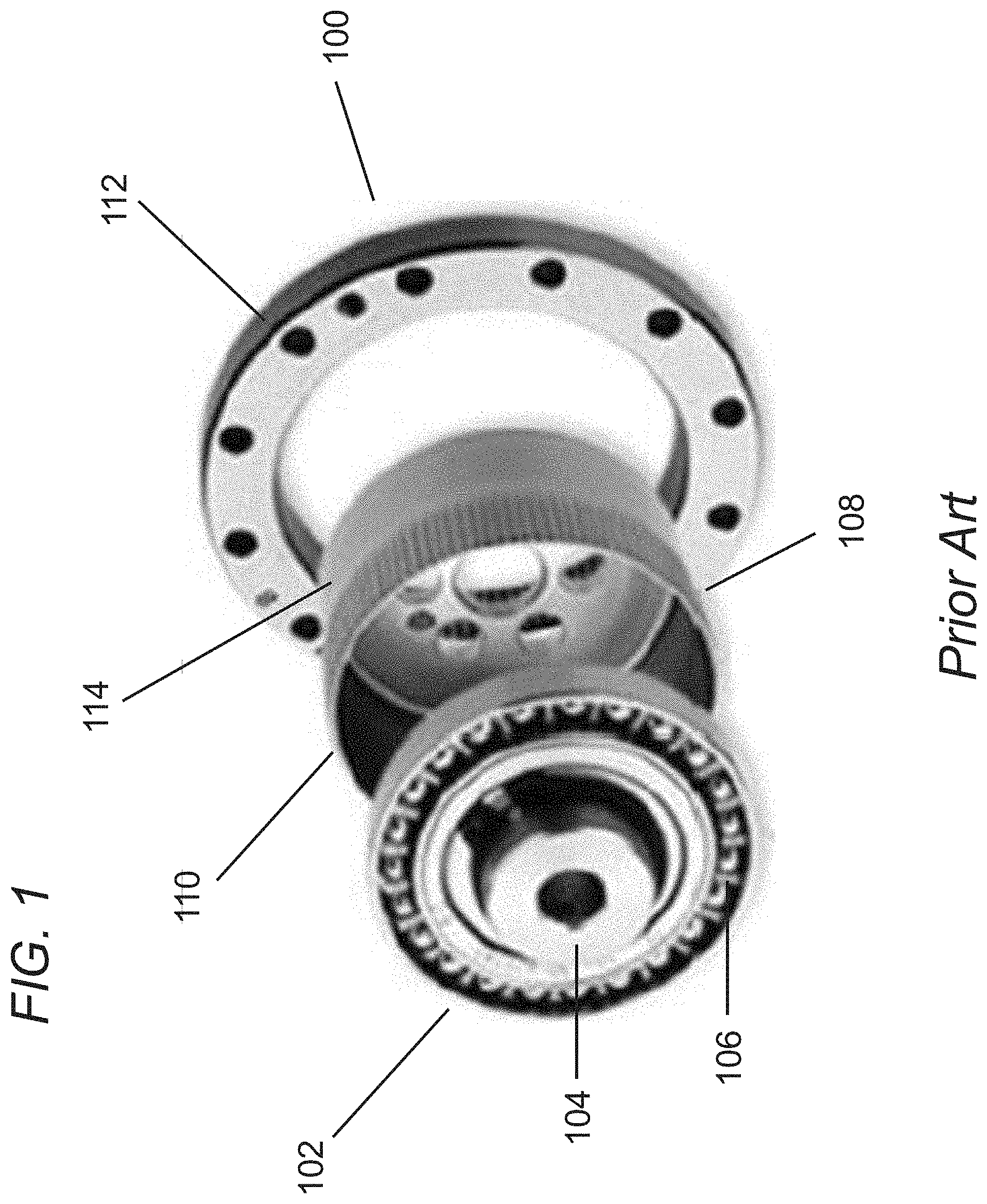
[0031] FIG. 1 illustrates a strain wave gear in accordance with the prior art.
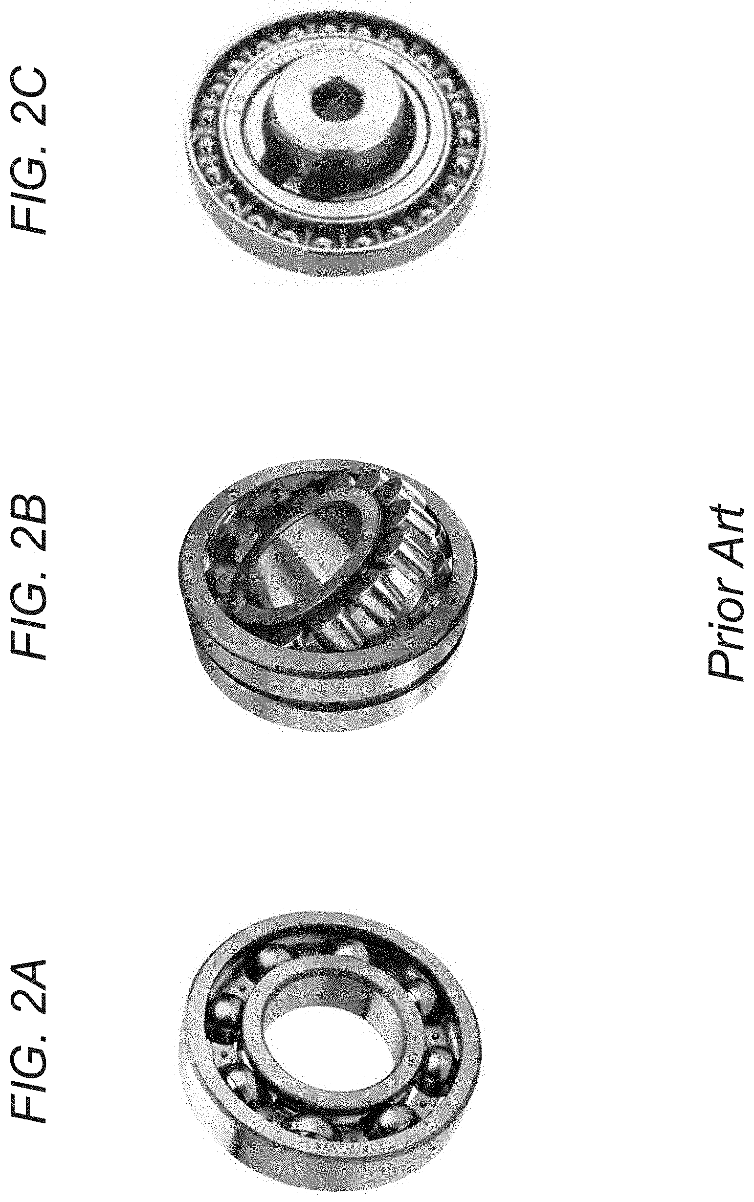
[0032] FIGS. 2A-2C illustrate low cost, commercially available ball bearings and roller bearings compared to the complex elliptical wave generator of a strain wave gear in accordance with the prior art.
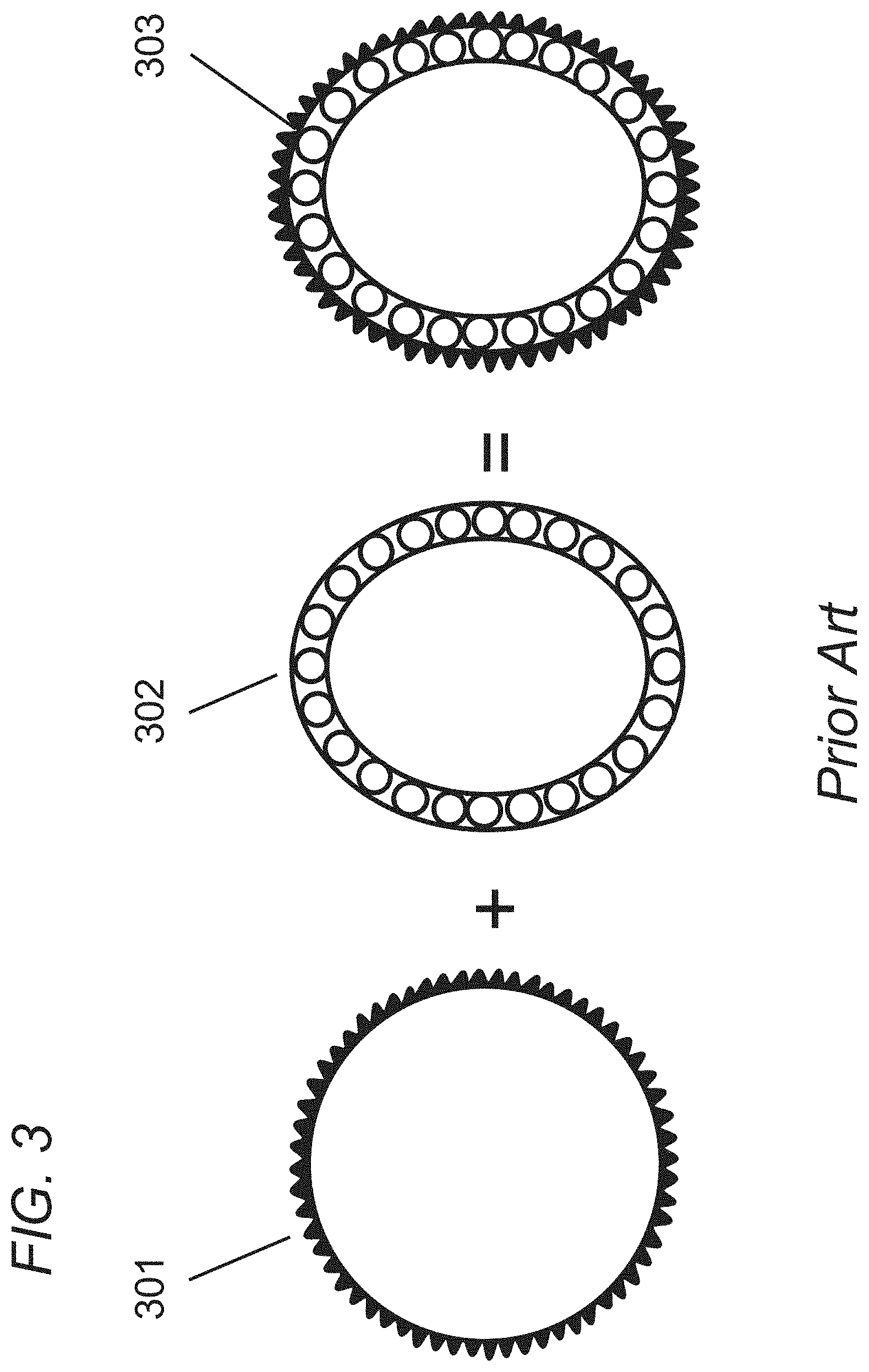
[0033] FIG. 3 illustrates a circular flexspline combined with an elliptical wave generator to form the inner two components of a strain wave gear, and the complete contact between the wave generator and the flexspline in accordance with the prior art.
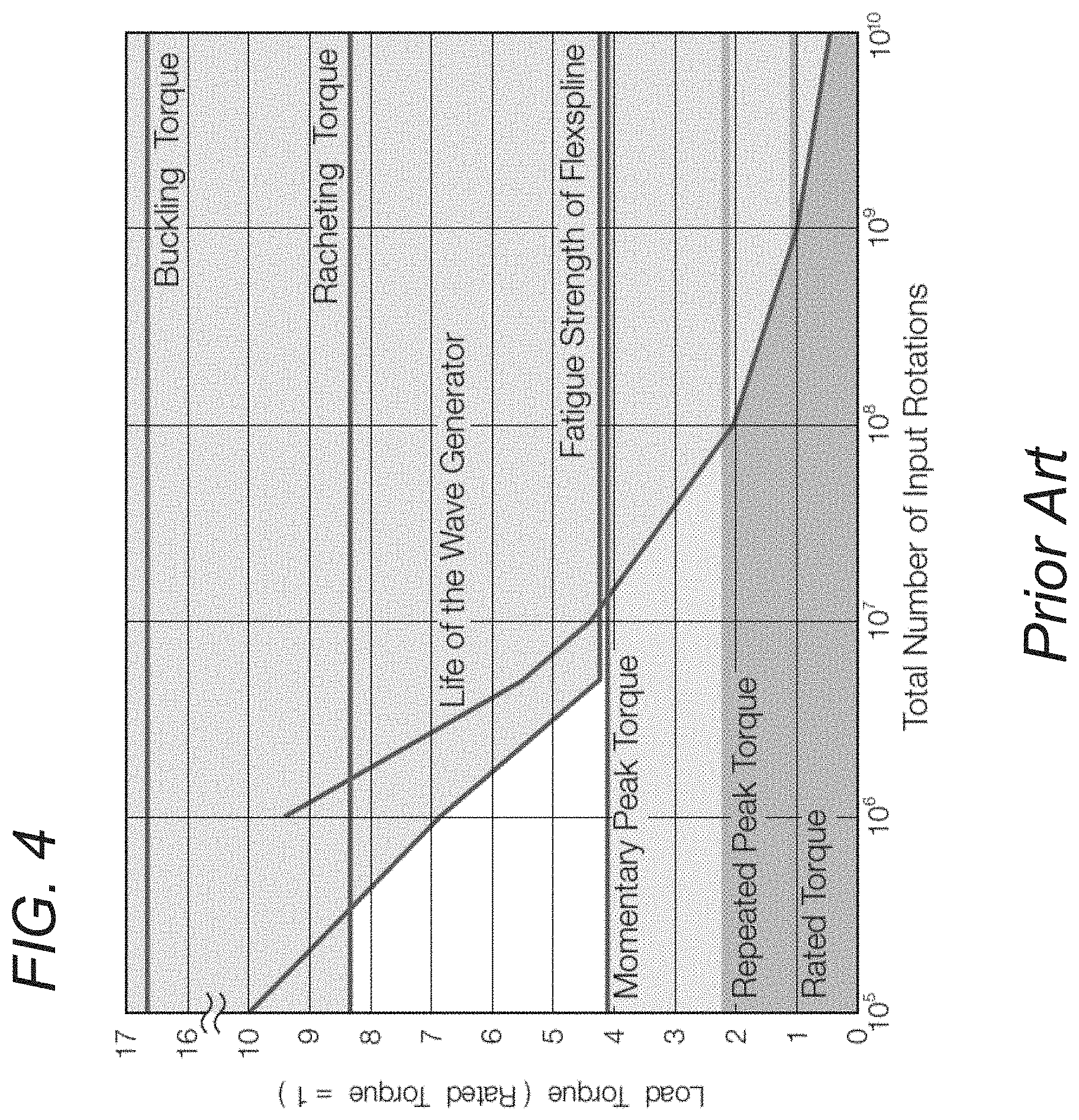
[0034] FIG. 4 illustrates the fatigue-life curve for commercial strain wave gears showing the predicted failure of the flexspline and the wave generator depending on the load above the rated torque, where the chart shows the various torque specifications relative to the rated torque, wherein the rated torque has been normalized to 1 for comparison in accordance with prior art.
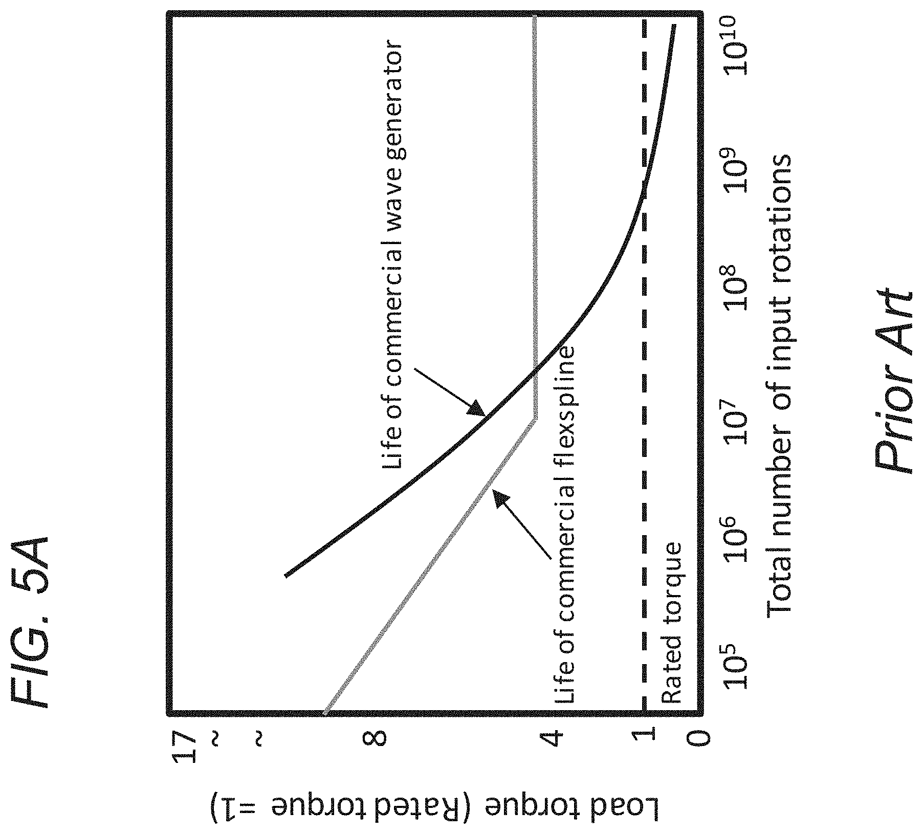
[0035] FIG. 5A conceptually illustrates a conventional fatigue-life curve for a commercial strain wave gear in accordance with prior art.
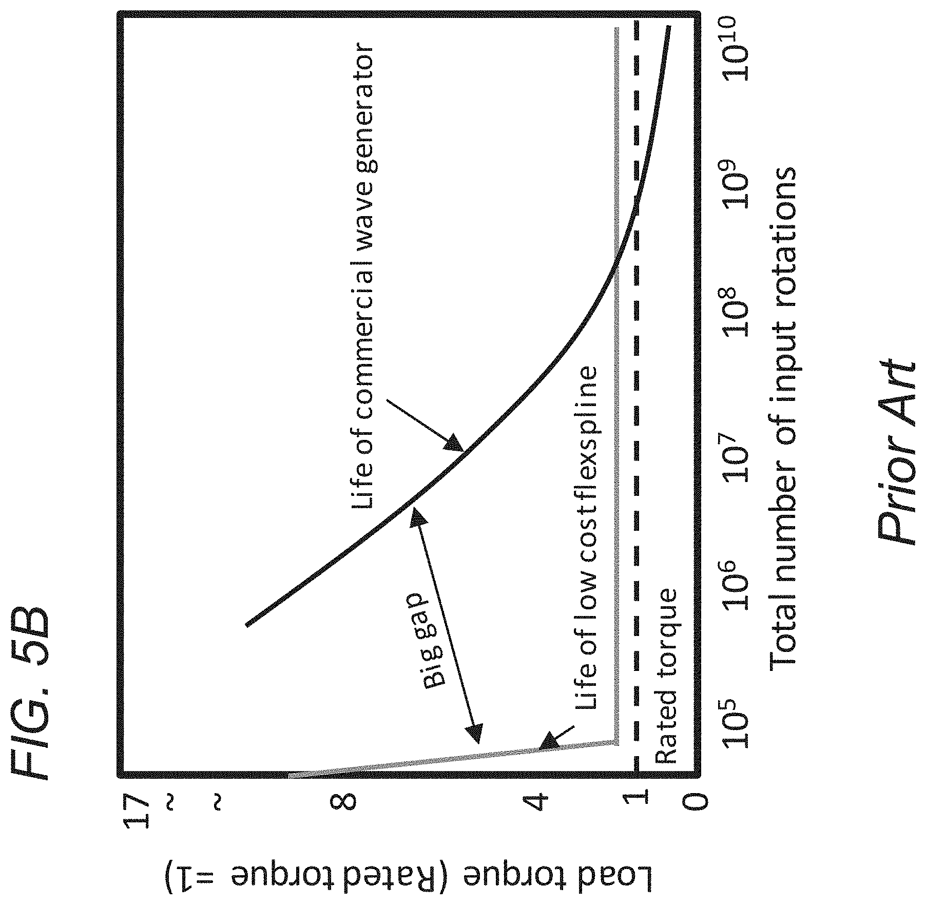
[0036] FIG. 5B conceptually illustrates a plot that shows when a low cost flexspline is substituted for the commercial flexspline, a large gap exists between the life of the flexspline and the life of the wave generator in accordance with prior art.
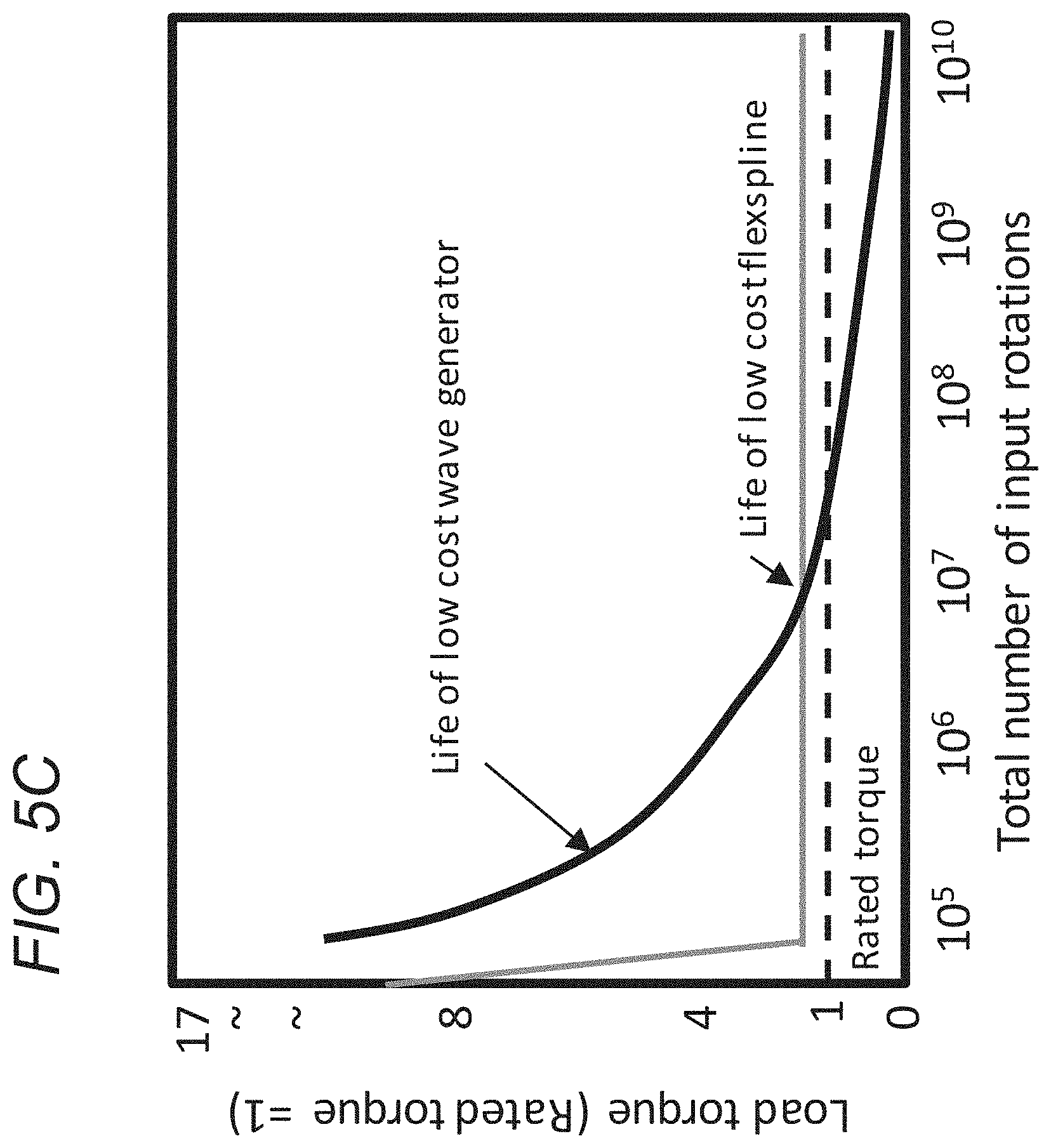
[0037] FIG. 5C conceptually illustrates a plot showing how a low cost wave generator, can be tailored to fail at similar life to a commercial flexspline in accordance with embodiments.
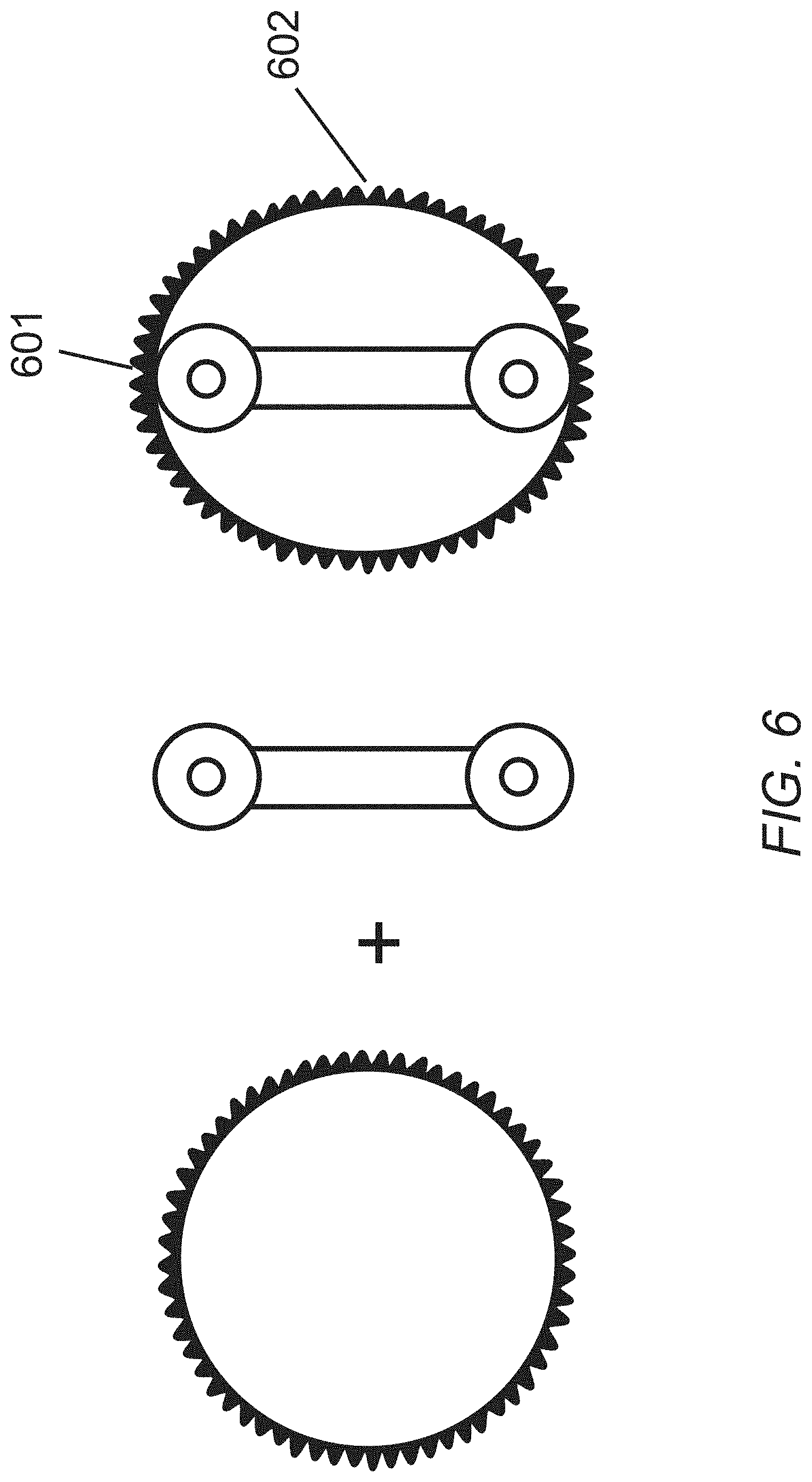
[0038] FIG. 6 illustrates a wave generator replacement in accordance with embodiments with two circular bearings on a shaft with length equal to the major axes of the ellipse.
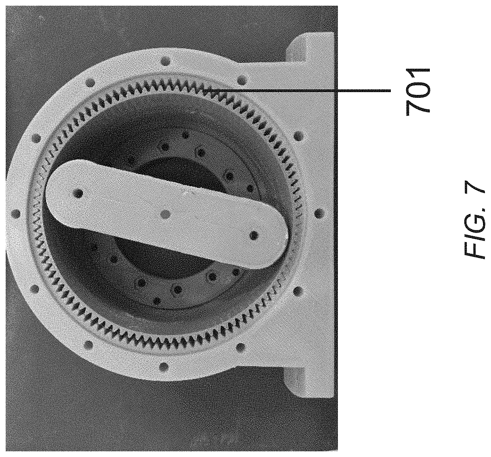
[0039] FIG. 7 illustrates 3D printed plastic flexsplines showing deformed flexsplines with two and three internal bearings making up the wave generator in accordance with embodiments.
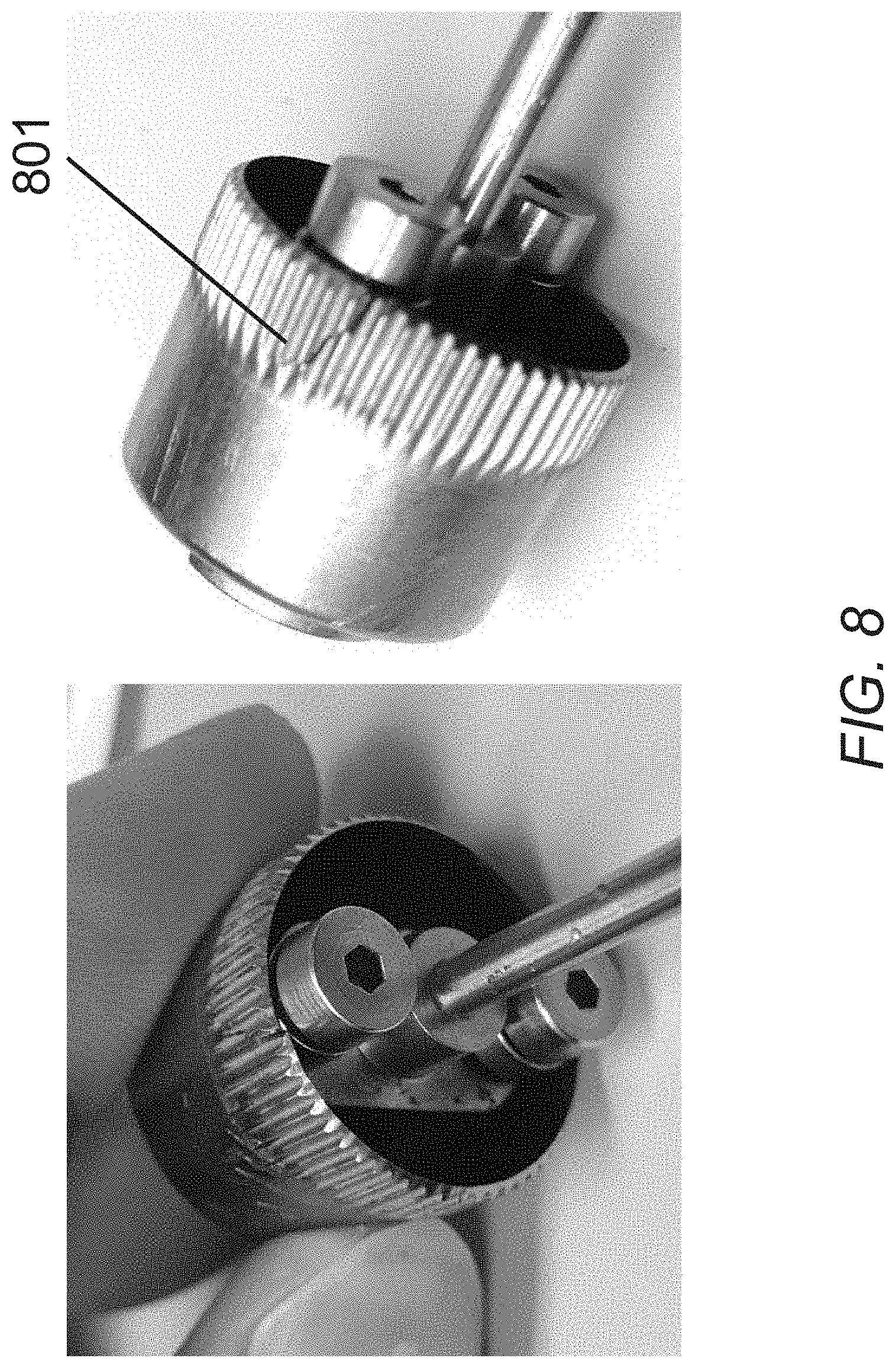
[0040] FIG. 8 illustrates cracks in the surface of a cast bulk metallic glass flexspline caused by a wave generator supporting the flexspline in only two locations in accordance with embodiments.
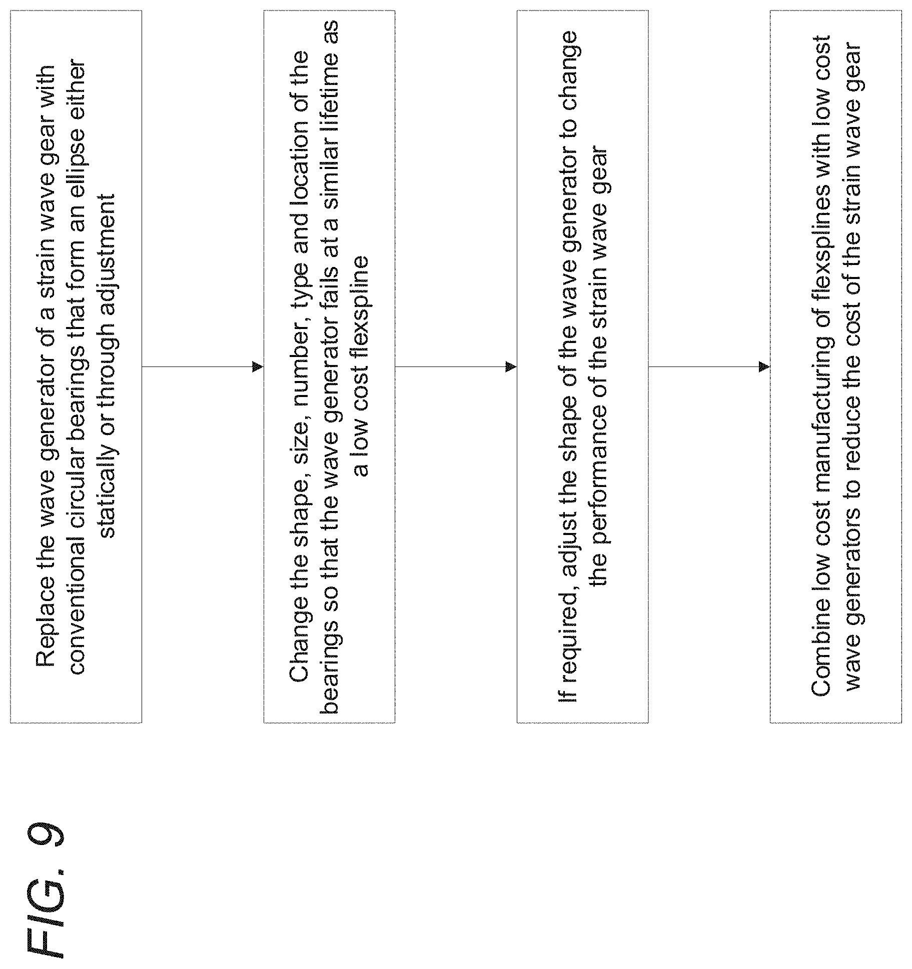
[0041] FIG. 9 illustrates a flow chart of the steps to design a low cost wave generator for metal strain wave gearing in accordance with embodiments.
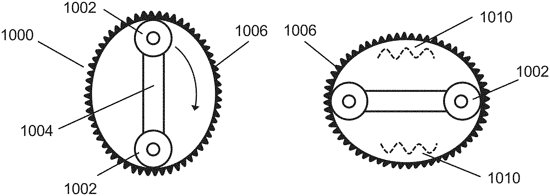
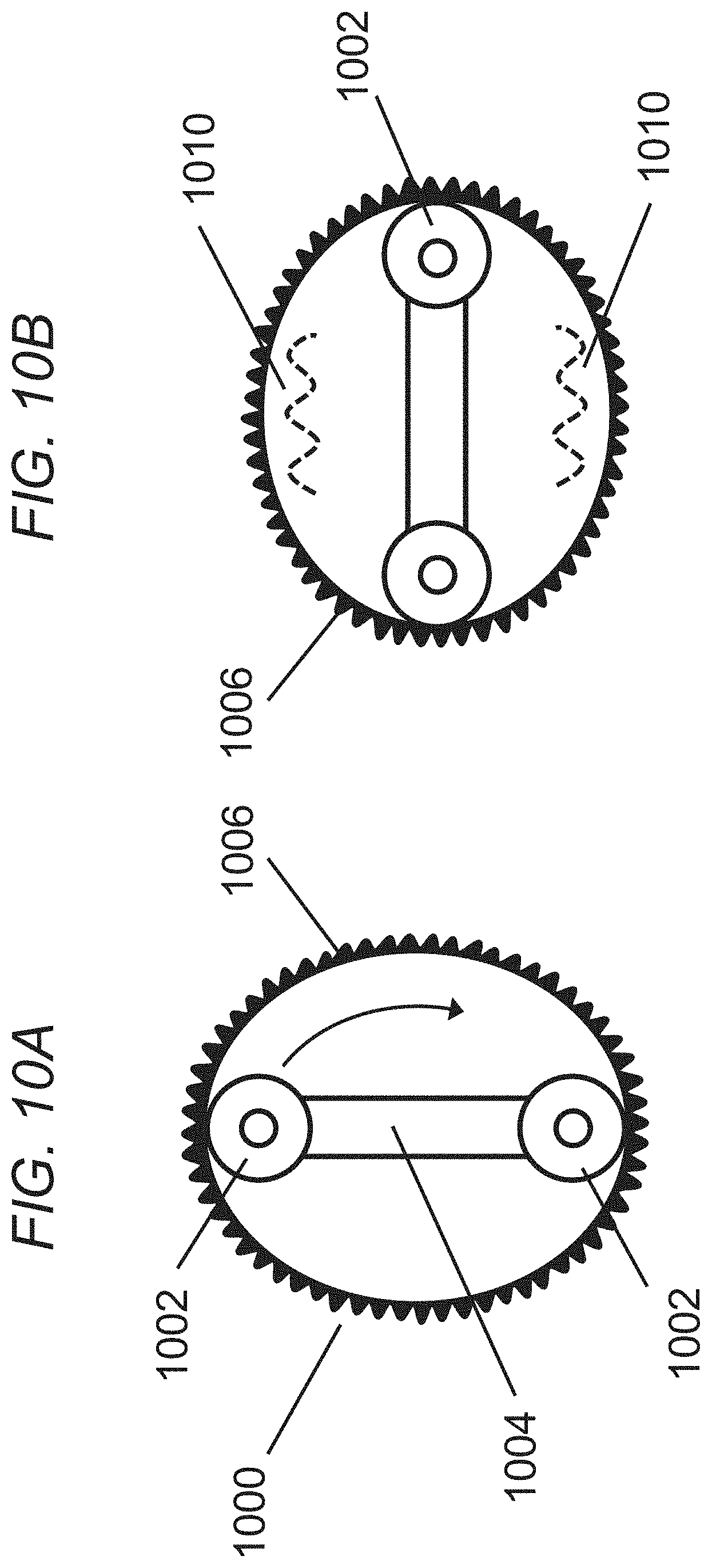
[0042] FIGS. 10A-10B illustrate the operation of a two bearing flexspline and the generation of oscillations in accordance with embodiments.
[0043] FIGS. 10C-10D illustrate the operation of a four bearing flexspline and the generation of oscillations in accordance with embodiments.
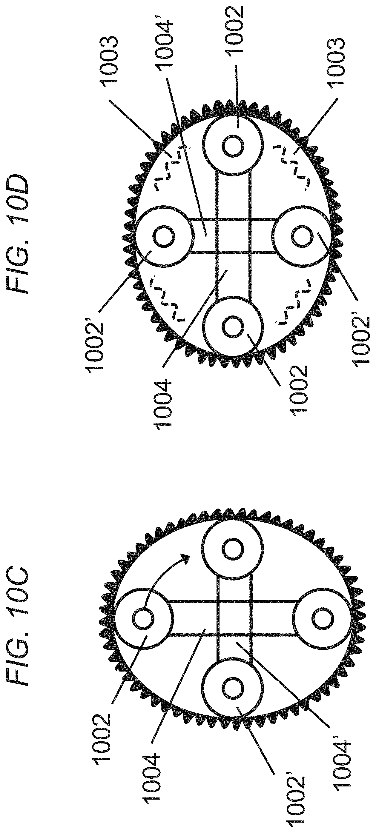
[0044] FIGS. 11A-11B illustrate a wave generator with 8 circular bearings making an ellipse, with each bearing located on adjustable arms in accordance with embodiments.
[0045] FIGS. 11C-11D illustrate a wave generator with 8 circular bearings making an ellipse, with each bearing located on a solid elliptical component in accordance with embodiments.
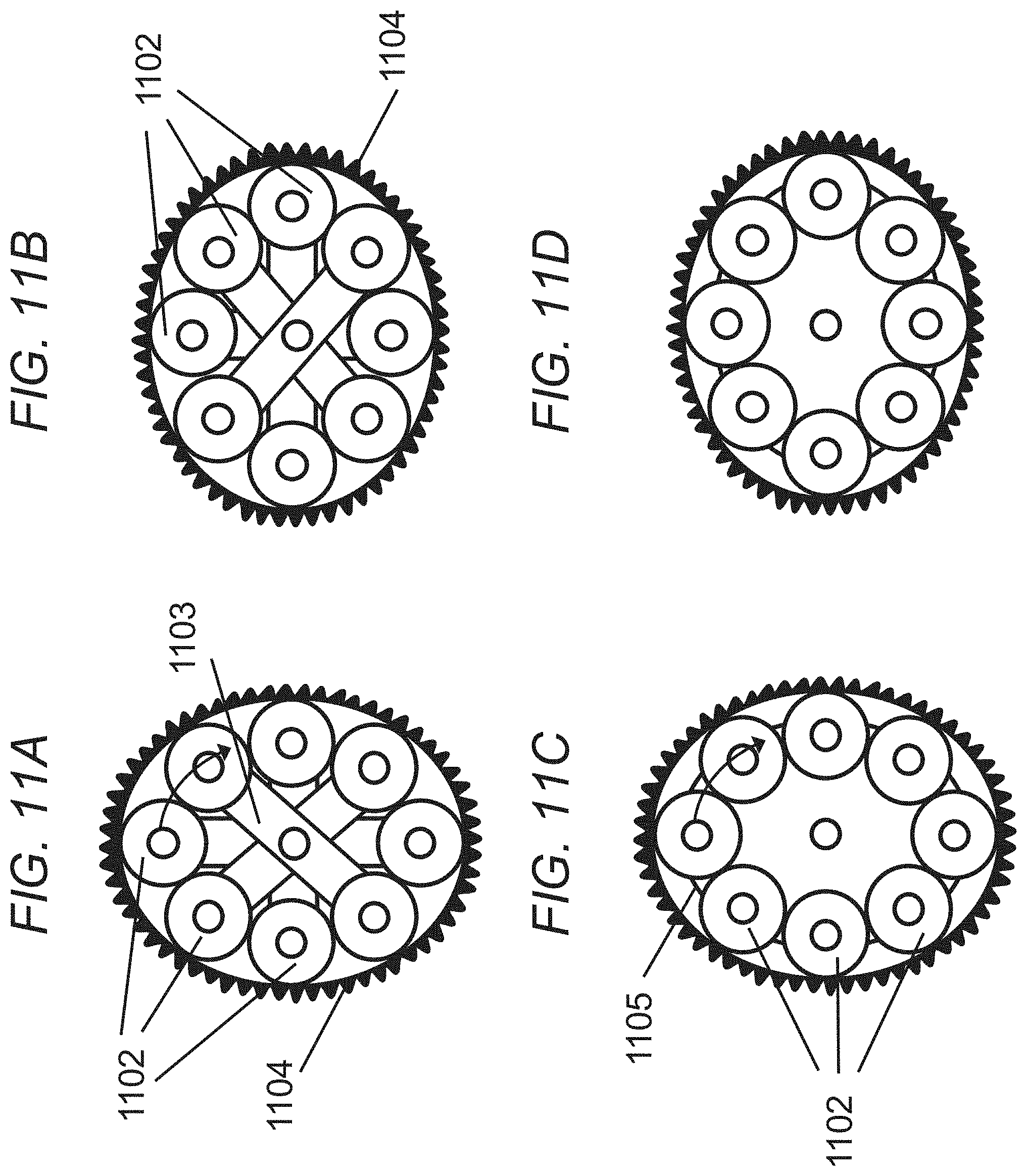
[0046] FIG. 12A illustrates a commercial wave generator in accordance with the prior art.
[0047] FIG. 12B illustrates a single arm wave generator with circular bearings in accordance with embodiments.
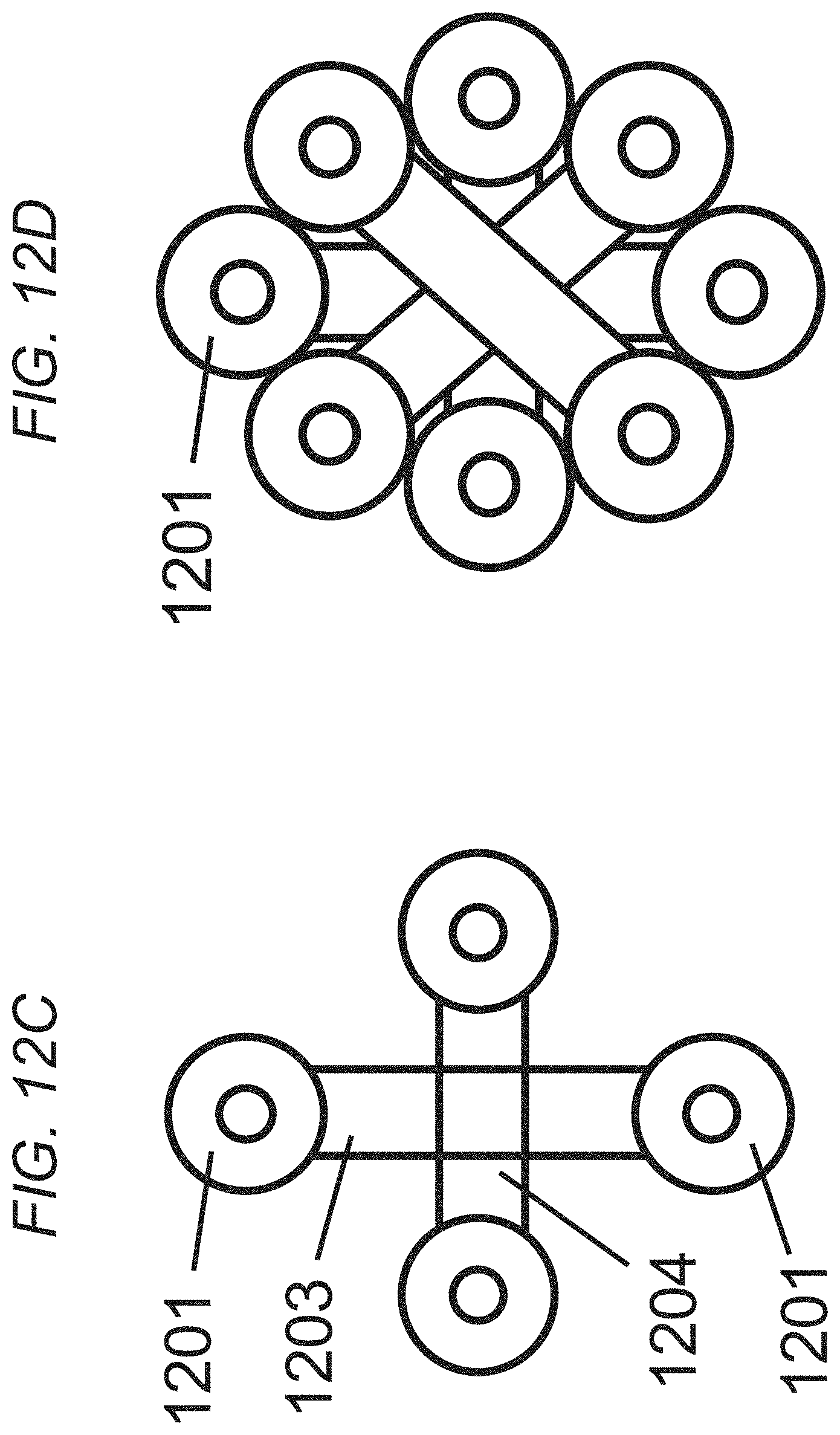
[0048] FIG. 12C illustrates different arrangements of bearings wherein the arms are crossed in accordance with embodiments.
[0049] FIG. 12D illustrates different arrangements of bearings of the multiple bearing wave generator in accordance with embodiments.
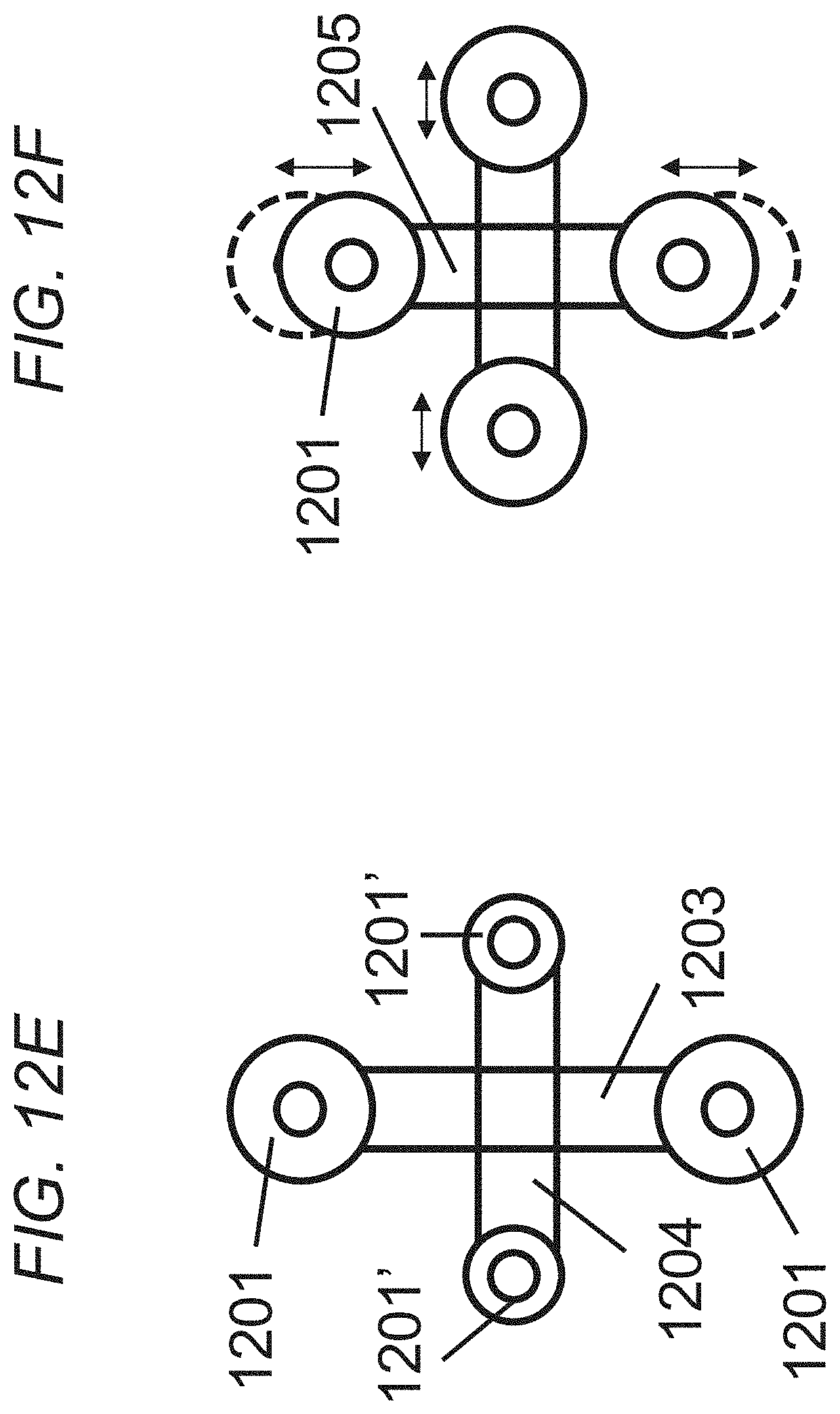
[0050] FIG. 12E illustrates different sizes of bearings where the arms are crossed with varying sized bearings to control contact stress in accordance with embodiments.
[0051] FIG. 12F illustrates different sizes of bearings where the arms are crossed with adjustable major and minor axes in accordance with embodiments.
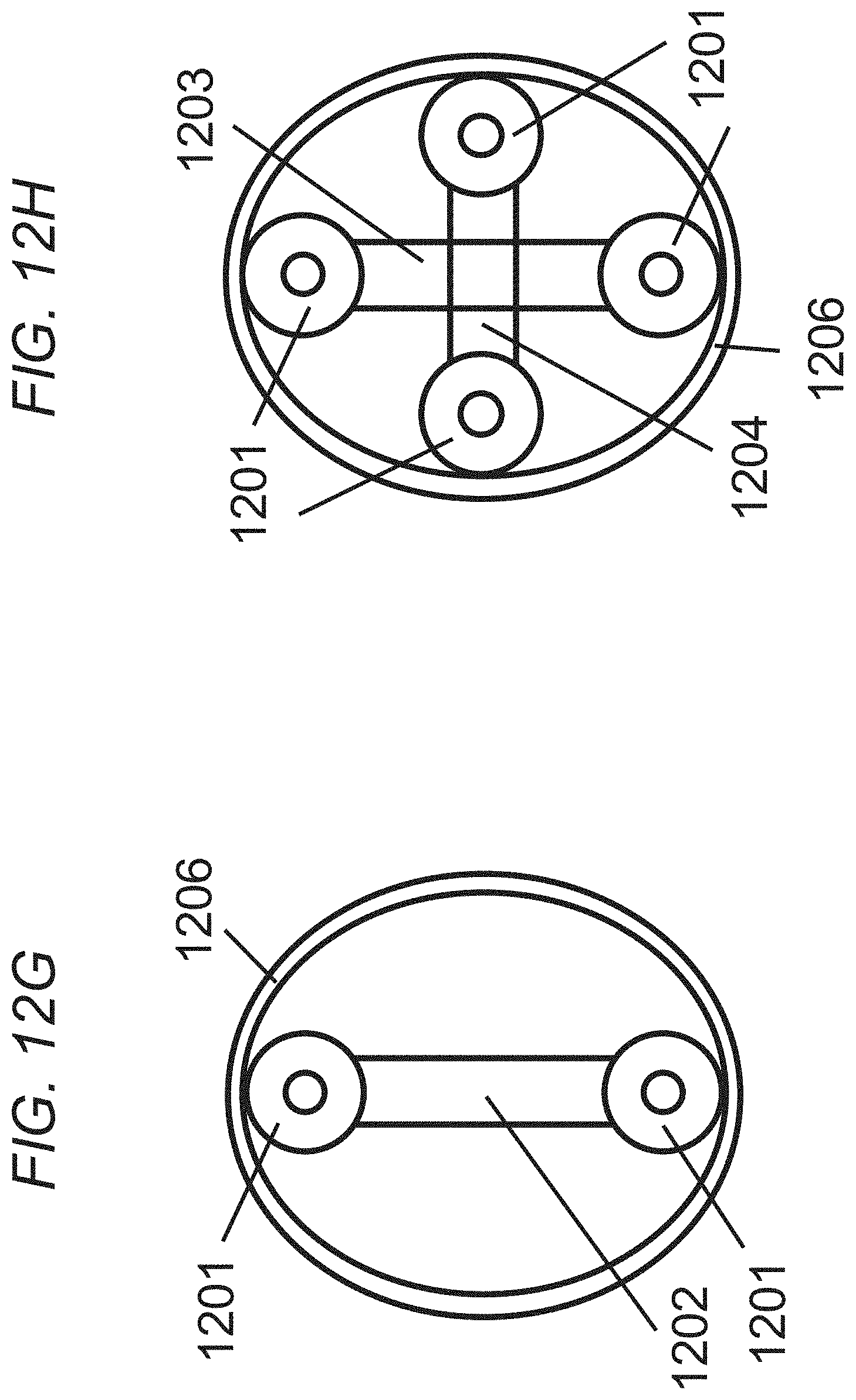
[0052] FIG. 12G illustrates single arm bearings used to stretch a circular ring where the bearing is not adjustable, but is low cost to manufacture in accordance with embodiments.
[0053] FIG. 12H illustrates crossed arm bearings used to stretch a circular ring where the bearing is not adjustable, but is low cost to manufacture in accordance with embodiments.
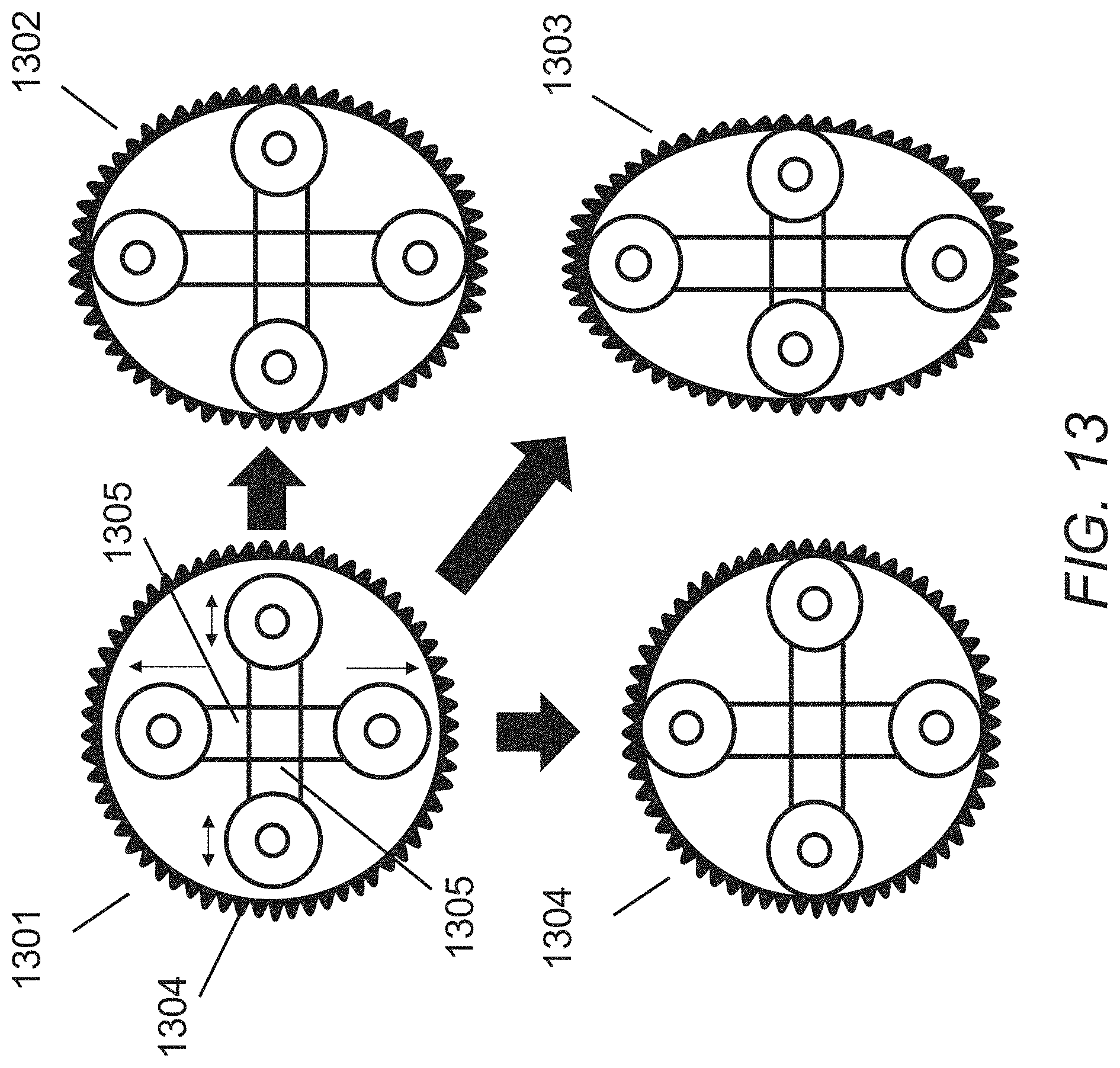
[0054] FIG. 13 illustrates the tunability of the current wave generator design where the location of the bearings can be moved to provide more or less flexing to the wave generator to change the efficiency and the torque rating of the strain wave gear in accordance with embodiments.
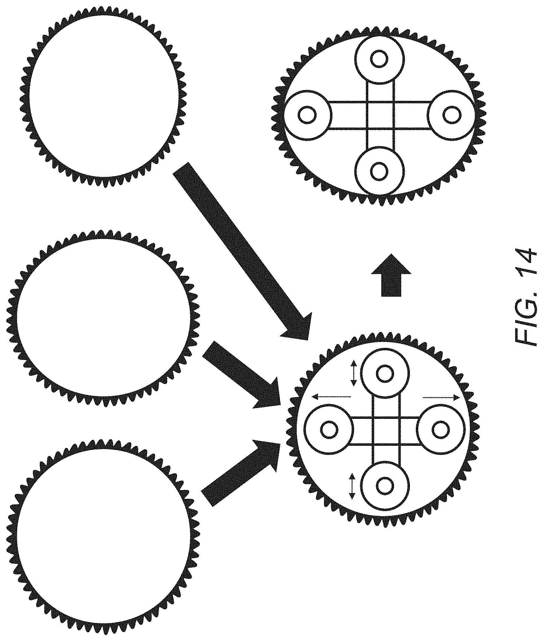
[0055] FIG. 14 illustrates an adjustable wave generator that may be used to accommodate manufacturing differences in flexsplines to assure a nominal performance of the total strain wave gear, where the adjustable wave generator can normalize imperfections in shape for consistent operations in accordance with embodiments.
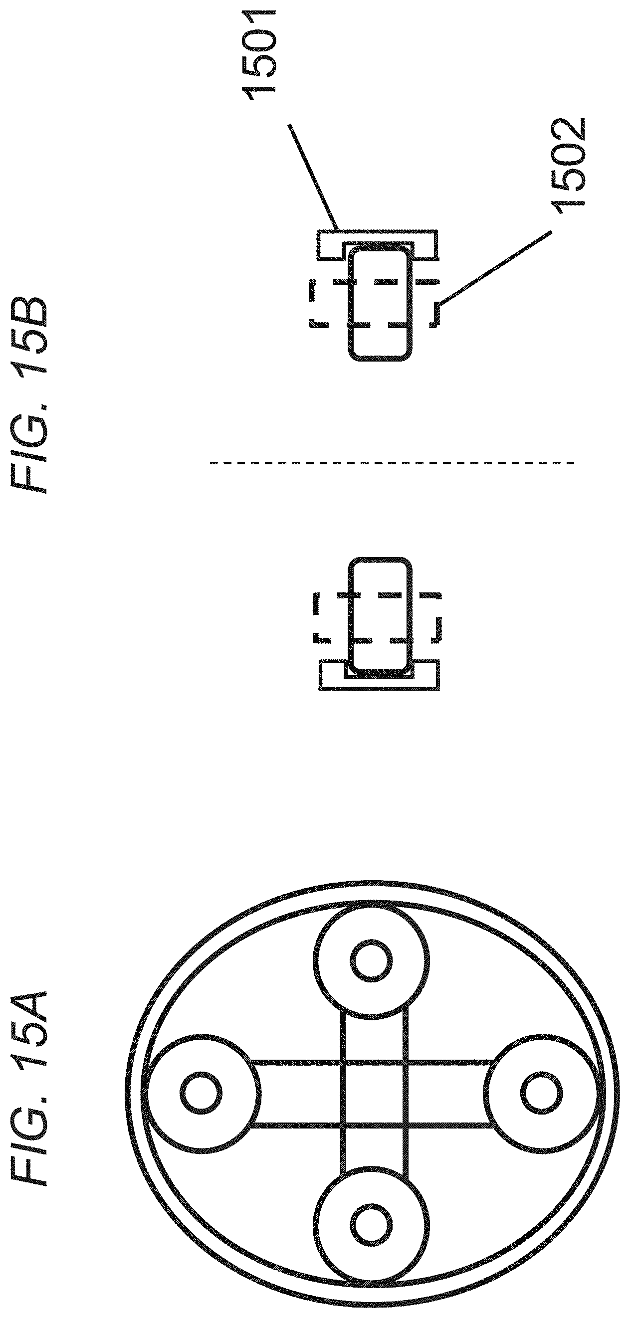
[0056] FIG. 15A illustrates a top view of a wave generator using bearings and a flexible ring where the ring incorporates a groove to prevent slippage off of the wave generator in accordance with embodiments.
[0057] FIG. 15B illustrates side view of a wave generator using bearings and a flexible ring where the ring incorporates a groove to prevent slippage off of the wave generator in accordance with embodiments.
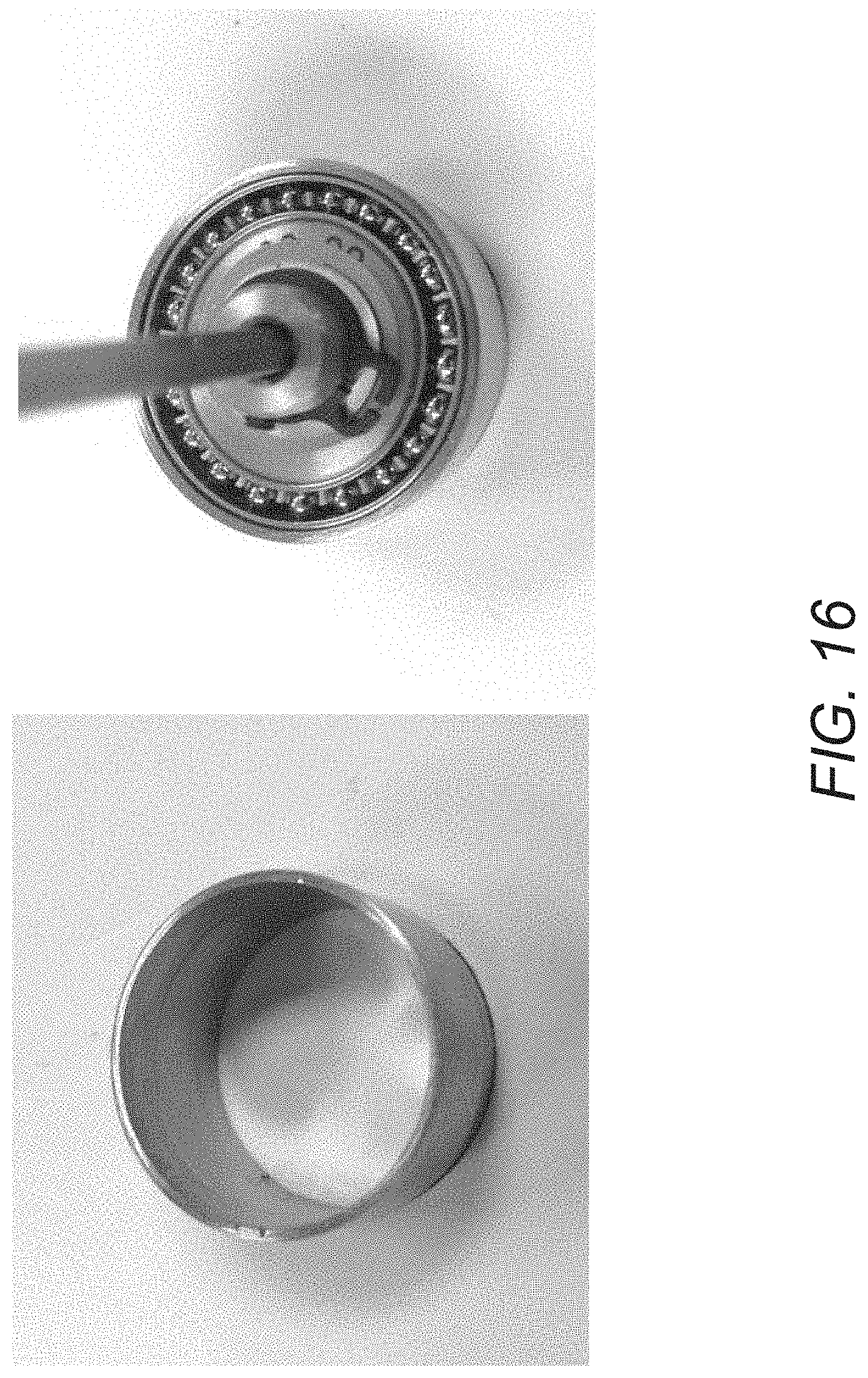
[0058] FIG. 16 illustrates an example of a flexible ring made from metallic glass that has been flexed using a conventional elliptical wave generator in accordance with embodiments.
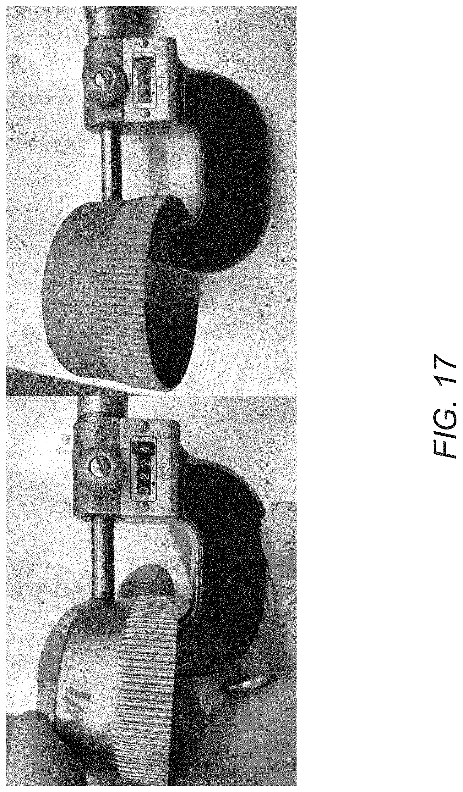
[0059] FIG. 17 illustrates a machined steel flexspline with a wall thickness of 0.22-0.20=0.02 inches, an as-printed flexspline with a wall thickness of 0.015 inches, and where variations in manufacturing can be mitigated by having adjustable wave generators that can accommodate any sized flexspline or that can fix non-circularity in the flexspline in accordance with embodiments.
DETAILED DESCRIPTION OF THE INVENTION
[0060] Turning now to the drawings, low cost wave generators for metal strain wave gears, and methods of their manufacture, are described. In many embodiments, the elliptical wave generator is replaced with circular bearings. In some embodiments, at least four circular bearings are used where at least four points of contact are maintained between the wave generator and the flexspline during operation. Many embodiments describe different configurations of such circular bearings. Many other embodiments highlight that the positions of the circular bearings can be adjusted to impart more or less deformation to the flexspline. Various such embodiments incorporate different sizes of circular bearings on the major and minor axes of an ellipse. The type and number of circular bearings can also be adjusted according to embodiments to modify the efficiency and the torque of the strain wave gear in the wave generator. In many embodiments, the wave generator has adjustable arms. In some other embodiments, the circular bearings are connected to a solid component. In some other embodiments, a flexible metal ring is placed between the circular bearings and the inside wall of the flexspline. any embodiments use roller bearings, ball bearings, or combination of both. In many embodiments, ceramic bearings are used. In many other embodiments, metal bearings are used. Many embodiments reveal that the position and number of bearings can increase the life of a flexspline made from a brittle bulk metallic glass alloy.
[0061] Harmonic drives are one of the driving factors in the early formulation of spacecraft design because they limit the size of the spacecraft. Harmonic drives are also used very heavily on Jet Propulsion Lab rovers, including many that were integrated into the Mars Exploration Rovers (MER). Developing low cost harmonic drives or high performance drives is game-changing for future NASA missions and for terrestrial robotics.
[0062] Harmonic drives were developed to take advantage of the elastic dynamics of metals, particularly the expansion of a metal ring to engage gear teeth without exceeding the elastic limit of the ring, which would cause permanent (i.e. plastic) deformation. The harmonic drive is made of three components: a wave generator, a flexspline (a.k.a. an inner race), and a circular spline (a.k.a. an outer race).
[0063] FIG. 1 illustrates an exploded view of a typical strain wave gear that can be fabricated from BMG-based materials in accordance with embodiments of the invention. In particular, the strain wave gear 100 includes a wave generator 102, a flexspline 108, and a circular spline 112. The illustrated wave generator 102 includes a wave generator plug 104 and a ball bearing 106. Importantly, the wave generator plug 104 is elliptical in shape, and is disposed within the ball bearing 106 so that the ball bearing 106 to conforms to the elliptical shape. In this arrangement, the outer race of the ball bearing 106 can rotate relative to the wave generator plug 104. In the illustrated embodiment, the flexspline 108 is depicted as being in the shape of a cup; notably, the outer rim of the cup includes a set of gear teeth 110. In the illustration, the flexspline is fitted over the ball bearing, such that the outer rim of the flexspline conforms to the aforementioned elliptical shape. Note that in this arrangement, the ball bearing allows the flexspline to rotate relative to the wave generator plug. The circular spline, 112 is in the shape of a ring; importantly, the inner perimeter of the ring includes a set of gear teeth. Normally, there are more gear teeth on the circular spline 114 than on the flexspline 110. In many instances there are two more gear teeth on the circular spline 112 than on the flexspline 108. Typically, the flexspline 108 is fitted within the circular spline 112 such that the gear teeth of the flexspline 110 engage the gear teeth of the circular spline 114. Notably, because the gear teeth of the flexspline 110 conform to an elliptical shape, only the gear teeth proximate the major axis of the elliptical shape engage the gear teeth of the circular spline 114 in the usual case. Conversely, the gear teeth of the flex spline 110 that are proximate the minor axis of the elliptical shape are disengaged from the gear teeth of the circular spline 114. In many instances, 30% of the gear teeth of the flexspline 110 are engaged with the gear teeth of the circular spline 114. With this arrangement, the wave generator plug 104 can rotate in a first direction about the central axis of the elliptical shape, and thereby cause the flexspline 108 to rotate in a second opposite direction and at a different rate of rotation (generally slower) about the central axis of the elliptical shape. This can be achieved as the flexspline 108 is made of a flexible material that can accommodate the deflections that may result from the rotation of the wave generator plug 104.
[0064] The primary problem with current strain wave gear harmonic drives is the machining of the components, particularly the elliptical wave generator and the thin-walled flexspline. Much work has been done on low-cost manufacturing methods for producing the flexspline including through casting of bulk metallic glasses and metal additive manufacturing (also called 3D printing). (See e.g., U.S. Pat. No. 9,328,813 B2 to Hofmann et al., U.S. Pat. No. 10,151,377 B2 to Hofmann et al., U.S. patent application Ser. No. 15/918,831 to Hofmann et al., U.S. patent application No. 62/811,798 to Hofmann et al.; the disclosures of which are hereby incorporated by reference.) Although significant progress has been made decreasing the manufacturing cost of the flexspline through the use of improved casting and 3D printing techniques, the overall cost of such strain wave gears is still large due to the complexity associated with manufacturing the elliptical wave generator that deforms the flexspline to engage the gearing (FIG. 2).
[0065] Currently, all wave generators for standard strain wave gears are manufactured by creating an elliptical bearing race with ball bearings that run in the race separated by spacers and then a thin steel race with a groove for the bearings on the inner side and a smooth outer surface 302 for engaging the flexspline 301 in FIG. 3. 303 shows complete contact between the wave generator and the flexspline. To manufacture the wave generator, precision grinding must be used to create the elliptical race and then precision machining must be used, in combination with grinding, to make the flexible outer band/race.
[0066] The design of conventional wave generators for strain wave gearing has been optimized to maximum performance, including increasing the efficiency and the lifetime, while maximizing the running torque. For each strain wave gear, fatigue-life (also called S-N) curves (FIG. 4) are available that show the predicted failure mode depending on the torque the strain wave gear is operated at above the rated torque. Significant effort has been spent optimizing the machining of the steel flexspline such that the number of cycles until failure at various loads is in the millions. As such, the wave generator has been designed to fail at approximately 10% longer life than the flexspline at high torques and near the rated torque. Despite this conventional design principal, the wave generator is still the primary mode of failure (FIG. 5A).
[0067] The issue with low cost manufacturing (or customizable manufacturing) of strain wave gears is that when new techniques are used to manufacture the flexspline, the number of cycles until failure dramatically decreases. For example, bulk metallic glass flexsplines tend to crack at a much lower number of cycles than machined steel. 3D printed metals have surface roughness, porosity and other defects that dramatically reduce their lifetimes. In cases where a low cost flexspline is utilized to decrease cost or change the operating conditions (like with cold capable flexsplines), the standard wave generator has a much longer life than the flexspline (FIG. 5B). This creates a condition where the flexspline will always fail prior to the wave generator and undue cost is incurred manufacturing the wave generator, when much lower performance characteristics would be tolerable. Unfortunately, the manufacturing associated with creating the elliptical wave generator cannot be easily modified to reduce its cost and the standard design is not easily adjustable.
[0068] Many embodiments of the invention describe wave generators and methods of fabricating wave generators for low cost strain wave gears that are adjustable to any flexspline, and can also support brittle flexsplines and extend their life (FIG. 5C). Many embodiments include the fabrication of wave generators using commercially available bearings located on the circumference of an ellipse that can simultaneously deform the flexspline at the major axis of the ellipse but also provide support at the minor axis to prevent oscillations and to improve efficiency.
Embodiments of Wave Generators Implementing Novel Bearing Arrangements
[0069] Although the difficulty in manufacturing wave generators for strain wave gears are well-known, substitutes for the standard complex wave generators have been difficult to develop. Various embodiments implement strain wave gears that replace the wave generator with conventional circular bearings disposed on one or more shafts. FIG. 6 depicts the replacement of a wave generator with two circular bearings on a shaft with length equal to the major axes of the ellipse. An issue with this design is that there are only two points of contact 601 between the wave generator and the flexspline resulting in a large area of unsupported flexspline wall 602. FIG. 7 shows examples of 3D printed plastic flexsplines, where circular bearings replace the wave generator. In FIG. 7, two circular bearings on a shaft structure create large unsupported flexspline regions 701. FIG. 8 shows a wave generator incorporating a two circular bearing design supporting the flexspline in only two locations. As shown, in such a design cracks 801 often develop in the surface of the cast bulk metallic glass flexspline.
[0070] As summarized in FIG. 9, wave generators according to many embodiments are fabricated using low-cost and commercially available ball bearings or roller bearings that are distributed around the circumference of an ellipse made through a solid support structure and that all rotate amongst their local axis to provide an elliptical motion to the flexspline. In various embodiments, at least four or more points of contact are disposed between the wave generator and the flexspline to prevent excessive flexing and oscillations that occur in brittle flexsplines which will decrease their lifetime.
[0071] As shown in FIGS. 10A to 10D, strain wave gears 1000 according to embodiments incorporate a novel wave generator that replaces the conventional wave generator and ball bearing element with a plurality of individual bearings 1002 disposed at opposite ends of elongated arms 1004. These bearing arms are disposed within a flexspline 1006, which itself can then be disposed in a conventional relation to a circular spline (not shown).
[0072] Turning the figures more specifically, FIGS. 10A and 10B show an elliptical wave generator comprising two bearings 1002 disposed on opposite ends of a single arm 1004. The length of the arm and the circular bearings equal the length of the long axis of the ellipse (FIG. 10A). The circular bearings 1002 can be ball bearings or roller bearings. When the arm rotates 90 degree clockwise (FIG. 10B), the unsupported regions 1010 of the flexspline 1006 oscillate. The oscillation leads to a decrease in the flexspline lifetime. Accordingly, many embodiments replace the wave generator with four or more bearings 1002 configured along opposite supporting arms to reduce the unsupported regions in the flexspline, thereby improving the flexspline performance, as shown in FIG. 10C. In embodiments incorporating a four bearing elliptical wave generator, every two bearings 1002 & 1002' are disposed on the opposite ends of a supporting arm 1004 & 1004'.
[0073] As shown in FIGS. 10C and 10D, in many such embodiments one of the support arms 1004 with two bearings has the length of the major axis of the ellipse, and the other support arm 1004' with two bearings has the length of the minor axis of the ellipse. During operation, the rotation of the wave generator (FIG. 10D) generates reduced flexspline oscillation compared to FIG. 10B.
[0074] Although embodiments having two and four bearings on individual arms are shown in these figures, it will be understood that many other configurations of bearings may be implemented according to embodiments. For example various embodiments implement the bearings are located on pins and built into a solid piece. Some embodiments implement eight circular bearings as the wave generator, as depicted in FIGS. 11A and 11B. In some such embodiments, as shown the bearings 1102 may be disposed on adjustable arms 1103. As shown, the eight circular bearings 1102 make an ellipse. As described above, as the wave generator rotates, the eight bearings offer more supported area of the flexspline 1104. In various other embodiments, eight circular bearings 1102 may be located on a solid elliptical component 1105 instead of individual arms (FIG. 11C). Such a configuration enables the rotation of the wave generator while offering further support around the flexspline (FIG. 11D).
[0075] Substituting circular bearings, according to embodiments, in place of the elliptical wave generator bearing causes a decrease in the efficiency of the strain wave gear as a whole. However, the large cost savings associated with using commercially available, low cost bearings in place of the wave generator, allows for the production of low cost wave generators and strain wave gears such that they can be employed in a wider variety of industries.
[0076] By using multiple bearings (of the same or different sizes), adjustable locations, and even a thin flexible ring, fine tuning of the performance of the strain wave gear is possible. Moreover, by placing bearings on the ends of adjustable arms, in accordance with various embodiments, small modifications can be made to the length of the elliptical axis which can fine-tune the torque on the flexspline or normalize the torque of the flexspline in the case that some manufacturing error exists. For example, an adjustable wave generator can correct the error in a 3D printed flexspline that is not exactly circular. Moreover, the wave generator can have components that are readily replaced during operation, which may increase the overall life of the strain wave gear. Such modifications are not possible in conventional elliptical strain wave gears, as featured in FIG. 12A, unless the entire wave generator is replaced.
Embodiments Implementing Wave Generators with Variable Numbers of Bearings
[0077] Although the above discussion has focused on strain wave gears with specific numbers of bearings, it will be understood that embodiments may use different numbers of bearings to replace the wave generator of a metal strain wave gear. FIGS. 12B, 12C, and 12D show respectively embodiments where the conventional elliptical wave generator is replaced with at least two circular bearings, at least four circular bearings, and at least eight circular bearings. As shown, in many embodiment pairs of circular bearings 1201 are disposed at the opposite ends of support arms. In various embodiments, as shown in FIG. 12B, at least one support arm 1202 has a length equal to the major axis of the ellipse, such that there are at least two points of contact with the flexspline during the operation of the wave generator. In some embodiments, as shown in FIG. 12C, the longer support arm 1203 equals the major axis of the ellipse and the shorter support arm 1204 equals to the minor axis of the ellipse. In many embodiments, at least four points of contact are maintained between the wave generator and the flexspline during operation. In other embodiments, as shown in FIG. 12D, at least eight bearings 1201 are distributed evenly around the perimeter of the ellipse, and eight points of contact are kept with the flexspline during operation.
[0078] Although specific arrangements are shown, it will be understood that the circular bearing wave generators may be configured with varying amount of support to the flexspline. The greater the number of circular bearings, the more support the flexspline receives and the longer the flexspline lasts. Each additional set of bearings added to the wave generator extends the life of the flexspline by preventing unsupported areas from overly oscillating.
[0079] In many embodiments, the location of the bearings can be adjusted during operation of the strain wave gear using a feedback loop to tailor the performance of the drive to a desired value. In such embodiments, the torque on the flexspline can be increased or decreased by changing the location of the bearings in the wave generator.
Embodiments Implementing Wave Generators with Different Size of Bearings
[0080] Although embodiments having bearings of a single size are shown and described above, it should be understood that circular bearings having many different sizes may be implemented in wave generators according to embodiments. As depicted in FIG. 12E, various embodiments implement four circular bearings where two circular bearings 1201 on the same arm are of the same size, and the other circular bearings 1201' are the same size, but where the circular bearings 1201 are of a different size from the circular bearings 1201'. In many such embodiments, the long support arm 1203 may equal the length of the major axis of the ellipse while the short support arm 1204 equals the length of the minor axis. In various embodiments, the diameter of the circular bearings 1201 & 1201' are sized to be smaller than one half of the major axis of the ellipse of the strain wave gear operational size.
[0081] During operation, the wave generator may be inserted into the flexspline and then widened to form an elliptical shape. Different sizes of bearings allow modifications to the length of the elliptical axis and fine-tuning of the torque on the flexspline. In such embodiments, the torque on the flexspline can be increased or decreased by changing the size of the bearings in the wave generator.
Embodiments Implementing Wave Generators with Adjustable Arms
[0082] Although embodiments described above show rigid support arms, it will be understood that the location of the circular bearings may also be adjustable to provide more or less deformation to the flexspline as required. Various embodiments use adjustable arms 1205 in the four bearing wave generators, as shown in FIG. 12F. The adjustable wave generator allows for modifications of the elliptical axes, or for correcting errors in a flexspline that is not exactly circular, e.g., one that might be 3D printed. With the ability to adjust to different shapes, such wave generators are able to fine-tune the torque on the flexspline or normalize the torque of the flexspline when manufacturing errors exist.
[0083] In some embodiments, such flexibility can be used to increase or decrease the torque as needed on a single strain wave gear. FIG. 13 shows the tunability of the wave generator with adjustable arms 1305. The wave generator can be inserted into the flexspline 1304 and then widened to form an elliptical shape. The location of the bearings can be moved to provide more or less flexing to the wave generator. 1301 depicts the initial position of the wave generator where the wave generator is not touching the flexspline. During operation 1302, it can exhibit nominal operating torque on the strain wave gear. The adjustability also allows high operating torque on the strain wave gear as shown in 1303, or low operating torque as in 1304. The ability to adjust the strain wave gear directly changes the efficiency and the torque rating of the strain wave gear and may be optimized to improve performance.
[0084] In some other embodiments, the adjustable wave generator has the flexibility to normalize the performance of flexsplines with manufacturing differences. In such embodiments, the locations of the bearings can be modified to accommodate manufacturing differences in the flexsplines so that the efficiency of the strain wave gear between different parts varies by less than 10%. FIG. 14 shows an adjustable wave generator accommodating manufacturing differences in flexsplines to assure a nominal performance of the total strain wave gear. The flexspline can be made through casting or 3D printing process, and have variability in its circularity and size. The adjustable wave generator can normalize imperfections in the flexspline shape for consistent operations.
Embodiments Implementing Wave Generators with Flexible Rinds
[0085] In other embodiments, the wave generator is made with bearings capable of stretching a circular ring. FIG. 12G illustrates two bearings 1201 on a support arm 1202 configured to stretch a flexible circular ring, where the thin flexible metal ring 1206 is placed between the outside of the bearings and the inside wall of the flexspline and is in constant contact with the flexspline during operation. As the length of the arm 1202 is larger than the diameter of the circular ring, the ring displays an elliptical shape. With the constant support from the ring, the brittle flexspline that is in contact with the wave generator would tend to have an increased lifetime. Some other embodiments, as shown in FIG. 12H, use four bearings 1201 to stretch the flexible circular ring. In such embodiments, the long support arm 1203 with two bearings is longer than the ring diameter, and the short support arm 1204 with two bearings is shorter than the ring diameter. The two support arms are crossed at the center and perpendicular to each other. The circular ring is stretched into an ellipse with the two support arms. With the constant support from the ring 1206, the brittle flexspline that is in contact with the wave generator during operation would have a longer lifetime.
[0086] In some embodiments, the metal ring has an interior groove to prevent it from sliding off of the bearings and a smooth outer surface to mate with the flexspline. FIG. 15B provides a side view of such a configuration. The ring requires a groove 1501 to prevent slippage off of the wave generator. Similarly, the bearings need further bearings on the central axis 1502 to allow rotation and must be pinned or bolted in place to prevent slippage. FIG. 16 shows a flexible ring made from metallic glass that has been flexed using a conventional wave generator. The identical shape can be achieved using four bearings, as in FIG. 12H and FIG. 15, instead of the elliptical wave generator.
[0087] Many embodiments describe that the bearings are roller bearings, ball bearings or combinations of both. Some embodiments use metal bearings. Some other embodiments use ceramic bearings. In some other embodiments, the bearings are made, at least in part, from a bulk metallic glass. In some embodiments, the bearings are made from steel. In various embodiments, the bearings of the wave generator can be replaced individually after failing due to wear in the bearing. In some other embodiments, the flexible metal ring is made from a metallic glass based material.
[0088] Many embodiments show the position and number of bearings can increase the life of a flexspline made from a brittle bulk metallic glass alloy. In some embodiments, the wave generator fails within 10% of the number of cycles that the flexspline fails at. Many other embodiments describe that an adjustable wave generator can improve the fatigue performance of a bulk metallic glass-based flexspline by at least 10% compared to a standard elliptical wave generator.
[0089] Many embodiments describe the replacement of an elliptical wave generator with a series of bearings would render the performance of the drive drop dramatically, as the precision of the way pieces fit decreases. Moreover, each small bearing would be under an enormous load compared to the bearings in an elliptical wave generator, which will rapidly decrease their life. However, the low-cost flexsplines can be made at a fraction of the cost of machined steel versions using 3D printing and casting. These low cost flexspline have much worse performance and tolerance than machined versions and will fail much sooner than the wave generator. As such, the performance of the wave generator can be dramatically decreased to more closely match the failure of the flexspline. Many embodiments can also be used when customized materials are used in the flexspline for specific environmental conditions. For example, the flexspline may be made from high temperature materials, like Inconel or tantalum. The flexspline could be made from low temperature materials, like metallic glass; or it could be made from high wear resistant alloys, like tool steel. These flexsplines may be more brittle than standard steel, and thus do not require such a long life. As such, the wave generator can have its performance reduced to compensate. Many embodiments could be useful in the case of high temperature applications because ceramic ball bearings or roller bearings could be used in the wave generator, which could not be easily integrated into a commercial wave generator.
DOCTRINE OF EQUIVALENTS
[0090] As can be inferred from the above discussion, the above-mentioned concepts can be implemented in a variety of arrangements in accordance with embodiments of the invention. Accordingly, although the present invention has been described in certain specific aspects, many additional modifications and variations would be apparent to those skilled in the art. It is therefore to be understood that the present invention may be practiced otherwise than specifically described. Thus, embodiments of the present invention should be considered in all respects as illustrative and not restrictive.
* * * * *
D00000
D00001
D00002
D00003
D00004
D00005
D00006
D00007
D00008
D00009
D00010
D00011
D00012
D00013
D00014
D00015
D00016
D00017
D00018
D00019
D00020
D00021
D00022
D00023
XML
uspto.report is an independent third-party trademark research tool that is not affiliated, endorsed, or sponsored by the United States Patent and Trademark Office (USPTO) or any other governmental organization. The information provided by uspto.report is based on publicly available data at the time of writing and is intended for informational purposes only.
While we strive to provide accurate and up-to-date information, we do not guarantee the accuracy, completeness, reliability, or suitability of the information displayed on this site. The use of this site is at your own risk. Any reliance you place on such information is therefore strictly at your own risk.
All official trademark data, including owner information, should be verified by visiting the official USPTO website at www.uspto.gov. This site is not intended to replace professional legal advice and should not be used as a substitute for consulting with a legal professional who is knowledgeable about trademark law.