Methods And Apparatus For Top To Bottom Expansion Of Tubulars Within A Wellbore
Whiddon; Richard Murray ; et al.
U.S. patent application number 16/802717 was filed with the patent office on 2020-09-03 for methods and apparatus for top to bottom expansion of tubulars within a wellbore. The applicant listed for this patent is Oil States Industries, Inc.. Invention is credited to Gary Michael Thigpen, Richard Murray Whiddon.
| Application Number | 20200277833 16/802717 |
| Document ID | / |
| Family ID | 1000004683120 |
| Filed Date | 2020-09-03 |


View All Diagrams
| United States Patent Application | 20200277833 |
| Kind Code | A1 |
| Whiddon; Richard Murray ; et al. | September 3, 2020 |
METHODS AND APPARATUS FOR TOP TO BOTTOM EXPANSION OF TUBULARS WITHIN A WELLBORE
Abstract
One illustrative method for top to bottom expansion of tubulars within a wellbore comprises positioning the tubular, with an expansion mandrel positioned therein, within the well and expanding the tubular by forcing the expansion mandrel through the tubular in a down-hole direction of the well while forcing well fluid displaced by the expansion of the tubular into the formation.
| Inventors: | Whiddon; Richard Murray; (Porter, TX) ; Thigpen; Gary Michael; (Houston, TX) | ||||||||||
| Applicant: |
|
||||||||||
|---|---|---|---|---|---|---|---|---|---|---|---|
| Family ID: | 1000004683120 | ||||||||||
| Appl. No.: | 16/802717 | ||||||||||
| Filed: | February 27, 2020 |
Related U.S. Patent Documents
| Application Number | Filing Date | Patent Number | ||
|---|---|---|---|---|
| 62813078 | Mar 3, 2019 | |||
| Current U.S. Class: | 1/1 |
| Current CPC Class: | E21B 29/10 20130101; E21B 33/1285 20130101 |
| International Class: | E21B 29/10 20060101 E21B029/10; E21B 33/128 20060101 E21B033/128 |
Claims
1. A method of expanding a tubular within a well located in a formation, comprising: positioning the tubular, with an expansion mandrel positioned therein, within the well; and expanding the tubular by forcing the expansion mandrel through the tubular in a down-hole direction of the well while forcing well fluid displaced by the expansion of the tubular into the formation.
2. The method of claim 1, wherein the well fluid displaced by the expansion of the tubular are forced into the formation at a location below a bottom of the tubular.
3. The method of claim 1, wherein the well comprises an existing casing and wherein positioning the tubular comprises positioning the tubular adjacent the existing casing and wherein expanding the tubular comprises expanding the tubular toward the existing casing and wherein the well fluid displaced by the expansion of the tubular comprises well fluids positioned between the tubular and the existing casing.
4. The method of claim 1, wherein the existing casing comprises a plurality of perforations.
5. The method of claim 1, wherein the well comprises an open bore hole section that exposes a portion of the formation and wherein positioning the tubular comprises positioning the tubular adjacent the open bore hole section and wherein expanding the tubular comprises expanding the tubular toward the open bore hole section and wherein the well fluid displaced by the expansion of the tubular comprises well fluids positioned between the tubular and the open bore hole section.
6. The method of claim 1 wherein the tubular comprises a plurality of sections of pipe.
7. The method of claim 1, wherein, prior to positioning the tubular within the well, the method comprises: coupling a release sub to an upper end of the tubular; and coupling a guide nose to a lower end of the tubular.
8. A method of expanding a tubular within a well located in a formation, comprising: positioning an expansion assembly within a tubular, the expansion assembly comprising an expansion cone, a cone mandrel and a cone guide assembly, wherein the expansion cone is positioned adjacent the cone mandrel and an upper end of the cone mandrel and the cone guide is positioned on the cone mandrel adjacent a lower end of the cone mandrel; positioning the tubular, with the expansion assembly positioned therein, within the well; and expanding the tubular by forcing the expansion assembly through the tubular in a down-hole direction of the well such that the expansion cone engages and radially expands the tubular while forcing well fluid displaced by the expansion of the tubular into the formation.
9. The method of claim 8, wherein, prior to positioning the expansion assembly within the tubular, the method comprises coupling a float collar to a lower end of the cone mandrel, the float collar comprising an inverted check valve that, when closed, is adapted to block a flow of fluid through the inverted check valve in a down-hole direction of the well and wherein the method comprises positioning the expansion assembly within the well comprises positioning the expansion assembly having the float collar coupled thereto within the tubular.
10. An apparatus, comprising: at least one tubular; a release sub operatively coupled to a first end of the tubular; an expansion cone operatively coupled to a first end of a cone mandrel, the combination of the expansion cone and the cone mandrel positioned within the tubular below the release sub; and a float collar operatively coupled to a second end of the cone mandrel, the float collar comprising an inverted check valve that, when closed, is adapted to block a flow of fluid through the inverted check valve in a down-hole direction of the well.
11. The apparatus of claim 10, wherein the tubular comprises a plurality of sections of pipe.
12. The apparatus of claim 10, wherein the cone mandrel comprises a flange at an upper end of the cone mandrel and a cone retaining sleeve that is coupled to an outer surface of the cone mandrel, wherein the expansion cone is positioned above the cone retaining sleeve and wherein a portion of the expansion cone engages the flange.
13. The apparatus of claim 12, wherein the cone retaining sleeve is coupled to the outer surface of the cone mandrel by a threaded connection.
14. The apparatus of claim 10, wherein the at least one tubular comprises a pre-expanded portion and an expandable portion, wherein the expansion cone is adapted to be positioned within the pre-expanded portion of the tubular prior to any expansion of the expandable portion of the tubular.
15. The apparatus of claim 10 wherein the at least one tubular comprises a plurality of tubulars.
16. The apparatus of claim 10, further comprising a plurality of separate elastomer bands positioned around the outer surface of the at least one tubular.
17. The apparatus of claim 10, wherein the at least one tubular comprises: a first tubular that comprises a pre-expanded portion and an expandable portion; a second tubular that comprises a pre-expanded portion and an expandable portion; and an intermediate tubular that is operatively coupled to both the first tubular and the second tubular, the intermediate tubular having an inside diameter that is greater than a maximum outside diameter of the expansion cone.
18. The apparatus of claim 10 wherein the at least one tubular is adapted to be positioned against a formation in an uncased section of a wellbore.
19. The apparatus of claim 10, wherein the at least one tubular is a single length of pipe.
Description
BACKGROUND
1. Field of the Disclosure
[0001] Generally, the present disclosure relates to various novel methods and an apparatus for top to bottom expansion of tubulars within a wellbore.
2. Description of the Related Art
[0002] Typically, as a well is drilled, the casing becomes smaller in diameter as the well is drilled deeper. The reduction in size (e.g., internal diameter) of the casing limits the size of tubing that can be run into the well for ultimate production. All other things being equal, operators of oil and gas wells prefer that the internal diameter of the wells be as large as possible so as to provide for the greatest flexibility in terms of tool and techniques that may be employed to stimulate and/or maintain production from the well. Additionally, in some cases, the existing casing with a well may become damaged or otherwise need repair. In some of these applications, it may be desirable to insert a patch through the existing casing, position the patch at the location of the damaged casing and expand the patch downhole to repair the damaged casing. In yet other situations, it may be desirable to expand a tubular downhole to isolate an unconsolidated (i.e., non-cased) portion of a formation that is being drilled. This can be accomplished by running a piece or section of un-expanded casing into the drilled wellbore, and perhaps through existing casing within the wellbore, and thereafter expanding the previously un-expanded section of casing against the formation.
[0003] The present disclosure is directed to various novel methods and an apparatus for top to bottom expansion of tubulars within a wellbore that may eliminate or at least reduce one of more of the problems identified above.
SUMMARY
[0004] The following presents a simplified summary of at least one disclosed embodiment in order to provide a basic understanding of some aspects of the subject matter disclosed herein. This summary is not an exhaustive overview of all of the subject matter disclosed herein. It is not intended to identify key or critical elements of the subject matter disclosed herein or to delineate the scope of any claims directed to any of the subject matter disclosed herein. Its sole purpose is to present some concepts in a simplified form as a prelude to the more detailed description that is discussed later in the application.
[0005] Generally, the present disclosure is directed to various novel methods and an apparatus for top to bottom expansion of tubulars within a wellbore. One illustrative method disclosed herein includes positioning a tubular, with an expansion mandrel positioned therein, within the well and expanding the tubular by forcing the expansion mandrel through the tubular in a down-hole direction of the well while forcing well fluid displaced by the expansion of the tubular into the formation.
[0006] One illustrative apparatus disclosed herein includes a tubular, a release sub operatively coupled to a first end of the tubular, an expansion cone operatively coupled to a first end of a cone mandrel, wherein the combination of the expansion cone and the cone mandrel is positioned within the tubular below the release sub, and a float collar operatively coupled to a second end of the cone mandrel, the float collar comprising an inverted check valve that, when closed, is adapted to block a flow of fluid through the inverted check valve in a down-hole direction of the well.
BRIEF DESCRIPTION OF THE DRAWINGS
[0007] The disclosure may be understood by reference to the following description taken in conjunction with the accompanying drawings, in which like reference numerals identify like elements, and in which:
[0008] FIGS. 1-26 depict various illustrative novel methods and an apparatus for top to bottom expansion of tubulars within a wellbore.
[0009] While the subject matter disclosed herein is susceptible to various modifications and alternative forms, specific embodiments thereof have been shown by way of example in the drawings and are herein described in detail. It should be understood, however, that the description herein of specific embodiments is not intended to limit the invention to the particular forms disclosed, but on the contrary, the intention is to cover all modifications, equivalents, and alternatives falling within the spirit and scope of the invention as defined by the appended claims.
DETAILED DESCRIPTION
[0010] Various illustrative embodiments of the invention are described below. In the interest of clarity, not all features of an actual implementation are described in this specification. It will of course be appreciated that in the development of any such actual embodiment, numerous implementation-specific decisions must be made to achieve the developers' specific goals, such as compliance with system-related and business-related constraints, which will vary from one implementation to another. Moreover, it will be appreciated that such a development effort might be complex and time-consuming, but would nevertheless be a routine undertaking for those of ordinary skill in the art having the benefit of this disclosure.
[0011] The present subject matter will now be described with reference to the attached figures. Various structures, systems and devices are schematically depicted in the drawings for purposes of explanation only and so as to not obscure the present disclosure with details that are well known to those skilled in the art. Nevertheless, the attached drawings are included to describe and explain illustrative examples of the present disclosure. The words and phrases used herein should be understood and interpreted to have a meaning consistent with the under-standing of those words and phrases by those skilled in the relevant art. No special definition of a term or phrase, i.e., a definition that is different from the ordinary and customary meaning as understood by those skilled in the art, is intended to be implied by consistent usage of the term or phrase herein. To the extent that a term or phrase is intended to have a special meaning, i.e., a meaning other than that understood by skilled artisans, such a special definition will be expressly set forth in the specification in a definitional manner that directly and unequivocally provides the special definition for the term or phrase.
[0012] FIGS. 1-26 depict various illustrative novel methods and an apparatus for top to bottom expansion of tubulars within a wellbore. FIG. 1 is a side view of one illustrative embodiment of a tubular expansion apparatus 10 disclosed herein that is adapted for use in expanding tubulars, e.g., casing, pipe, etc., within a wellbore. The tubulars expanded using the method and apparatus disclosed herein may be of any size or configuration. FIG. 2 is a cross-sectional view taken along the long axis of the apparatus 10 depicted in FIG. 1. The novel devices and methods disclosed herein may be employed on any type of well, e.g., cased or uncased well, and in any well irrespective of the orientation, e.g., vertical or horizontal, of any portion of the wellbore. Thus, use of relative terminology such as "upper," "lower," "top" or "bottom" to refer to various components described herein should not be considered to imply any particular orientation of the wellbore, e.g., such relative terminology should not be interpreted as meaning that the methods disclosed herein may only be employed in wells having a substantially vertically oriented wellbore. Rather, such relative terminology should be understood to describe the relative position of the component or features of the component in the wellbore with respect to the up-hole direction of the wellbore or the down-hole direction of the wellbore. For example, a component referred to as an "upper component" could equally be referred to as an "up-hole component." Similarly, a "bottom" of a wellbore could be referred to as an "end" of the wellbore.
[0013] As shown in FIG. 1, in this illustrative example, the apparatus 10 comprises a clad release sub 12, an upper expansion joint 11, an intermediate tubular string 13, a lower expansion joint 15 and an illustrative guide nose 26. The upper expansion joint 11 comprises a tubular 14 with a pre-expanded housing section 14A, an expandable section 14B and a transition section 14C. The tubular 14 may comprise a single section of pipe or casing or it may comprise a plurality of sections of casing or pipe joined together. With continuing reference to FIG. 1, the lower expansion joint 15 comprises a tubular 17 with a pre-expanded housing section 17A, an expandable section 17B and a transition section 17C. The tubular 17 may comprise a single section of pipe or casing or it may comprise a plurality of sections of casing or pipe joined together. In terms of axial length, the tubulars 14, 17 may be of any desired length.
[0014] Also depicted in FIG. 1 is a plurality of elastomer sealing bands 110 that are axially spaced apart along the axial length of the expandable sections 14B, 17B. As depicted, the clad release sub 12 is operatively coupled to the pre-expanded housing section 14A, the transition section 14C is operatively coupled to the up-hole side 13A of the intermediate casing 13, the pre-expanded housing section 17A is operatively coupled to the down-hole side 13B of the intermediate casing 13 and the transition section 17C is operatively coupled to the guide nose 26. In one illustrative embodiment, the guide nose 26 is coupled to the transition section 17C by a plurality of shear pins (not shown). The connections between the upper expansion joint 11 and the intermediate casing 13, as well as the connection between the lower expansion joint 15 and the intermediate casing 13, may take a variety of forms. In one illustrative example, such connections may be flush joint casing connections. The elastomer bands 110 are pre-placed at various desired locations on the expandable sections 14B, 17B. In one illustrative application, the intermediate casing 13 is intended to straddle or cover a portion of the well (e.g., a portion of a perforated well casing or a portion of an un-cased well). Once the expansion process is completed, the elastomer bands 110 are compressed against the inside diameter of the existing tubular 42 (not shown in FIG. 1) (whether perforated on not) or the wall of the un-cased wellbore. Once the expansion process is completed, the elastomer bands 110 tend to secure and seal the upper and lower expansion joints 11, 15 in position within the well and thereby secure the position of the intermediate casing 13 within the well. The location and number of the elastomer bands 110 may be determined by the configuration of the well and/or wellbore operating conditions.
[0015] As discussed more fully below, the apparatus 10 includes an expansion cone 16 (see FIG. 2) that, when driven down-hole, is adapted to expand at least the expandable portions 14B, 17B of the tubulars 14, 17, respectively. In terms of diameter, the intermediate casing 13 may be of any desired size as long as the inside diameter of the intermediate casing 13 less than the maximum outside diameter of the expansion cone 16 and the outside diameter of the intermediate casing 13 fits within the well (e.g., within the inside diameter of a pre-existing casing positioned in the well or the diameter of an open un-cased bore hole). In terms of axial length, the intermediate casing 13 may be of any desired length (up to allowable carrying capacity). In one illustrative example, the intermediate casing 13 may have an axial length of several thousand feet, e.g., 6000 feet. As will be described more fully below, the immediate casing 13 will not undergo any appreciable radial expansion when the expandable sections 14B, 17B are radially expanded using the methods disclosed herein.
[0016] In one illustrative embodiment, the apparatus 10 may be positioned within a pre-existing tubular 42 (not shown in FIG. 1) that was previously positioned within a wellbore (not shown). The existing tubular 42 may or may not comprise a plurality of pre-existing perforations. In some applications, the methods and systems disclosed herein may be employed to cover a portion of existing casing that is simply damaged, e.g., due to corrosion. In other applications, the apparatus 10 may be positioned within an un-cased portion of a wellbore. The clad release sub 12 portion of the apparatus 10 is adapted to be directly coupled to a deployment string (not shown) extending from a surface location, e.g., a drilling rig, a vessel, etc. In one illustrative example, the apparatus 10 may be mechanically coupled to the deployment string via a box connection 78 on the clad release sub 12.
[0017] With reference to FIG. 2, additional components of this illustrative embodiment of the tubular expansion apparatus 10 are disclosed. An illustrative pre-existing tubular 42 positioned in the wellbore is also shown in FIG. 2. Also depicted in FIG. 2 are a shear sleeve 92 positioned within the clad release sub 12, an expansion cone 16, a cone mandrel 18 and a cone retainer 34. Other aspects, details and components of the illustrative apparatus may not be depicted in FIG. 2 so as not to overly complicate the drawings. However, such details of such additional components may be shown in more detailed drawings in the present application.
[0018] FIGS. 3-7 are slightly enlarged versions of portions of the axial length of the apparatus 10 shown in FIG. 2. More specifically, FIG. 3 is a cross-sectional view that primarily shows the clad release sub 12 and includes a portion the expansion cone 16 and the cone mandrel 18. FIG. 4 is a cross-sectional view that primarily shows the upper portion of the expansion cone 16 and an upper portion of the cone mandrel 18. The lowermost portion of the clad release sub 12 is also shown in FIG. 4. FIG. 5 is a cross-sectional view that primarily shows the lower portion 48 of the cone mandrel clad release sub 12 and the cone guide assembly 22. Also depicted in FIG. 5 is the intermediate casing 13 and a portion of a float collar 24 included with the apparatus. FIG. 6 is a cross-sectional view that primarily shows the float collar 24 and its engagement with the lower portion 48 of the cone mandrel 18. The lower tubular 17 is also depicted in FIG. 6. FIG. 7 is a cross-sectional view that primarily shows the guide nose 26 that is positioned at the lower end of the tubular 17.
[0019] As noted above, various aspects of the clad release sub 12 are depicted in FIG. 3. FIG. 9 is a plan view of a portion of the tubular 14 and the clad release sub 12 showing some of the components described below. The clad release sub 12 comprises the above-mentioned box connection 78, a plurality of fluid outlet openings 90, a plurality of shear pins 94, a shear sleeve 92, a plurality of inwardly-biased spring-loaded dogs 100, a biasing spring 102, an outer recess 104 in the shear sleeve 92 and an alignment pin 82 that is positioned in a slotted opening 84 formed in the tubular 14. A plurality of assembly access openings 101 are provided through the tubular 14 to permit installation of the spring loaded dogs 100. In the run-in position shown in FIG. 3, the inner surface 100X of the dogs 100 is biased against the outer surface of the shear sleeve 92 and a plurality of upper protrusions or lugs 100Y of the dogs 100 engage corresponding recesses in the inner surface of the tubular 14 so as to thereby prevent relative vertical movement between the tubular 14 and the clad release sub 12. The shear sleeve 92 comprises a through-bore 92T. As best seen in FIG. 9, positioning the alignment pin 82 in the slotted opening 84 fixes the relative rotational orientation between the tubular 14 and the clad release sub 12 while still permitting disengagement between the pin 82 and the slotted opening 84 by causing relative vertical movement between the tubular 14 and the clad release sub 12 when the dogs 100 are retracted from engagement with the recesses in the tubular 14. The shear pins 94 are installed through openings 95 in the tubular 14. The shear pins 94 releasably couple the shear sleeve 92 to the clad release sub 12. Also depicted in FIG. 3 is a plurality of seals 86, 88 positioned between the outer diameter of the clad release sub 12 and the inside diameter of the tubular 14 on opposite sides of the fluid outlet openings 90, and an upper seal 96 and a lower seal 98 positioned between the outside diameter of the shear sleeve 92 and the inside diameter of the clad release sub 12. Also depicted are a plurality of seals 106, 108 positioned between the outside diameter of the clad release sub 12 and the inside diameter of the tubular 14. Also depicted in FIG. 3 is an illustrative drop ball 80, the use of which will be described more fully below.
[0020] As will be appreciated by those skilled in the art after a complete reading or the present application, once released, the drop ball 80 is adapted to block the bore 92T through the shear sleeve 92. Once the ball 80 has landed, pressure above the ball 80 may be increased to shear the shear pins 94 and, thereafter force the shear sleeve 92 to travel in the down-hole direction within the clad release sub 12 until such time as a shoulder 92A on the shear sleeve 92 engages a shoulder 12X on the clad release sub 12. Of course, the drop ball 80 could be replaced with another device such as, for example, a drop dart (not shown). As will also be appreciated by those skilled in the art after a complete reading of the present application, once the shear sleeve 92 is released and moved to its most down-hole position within the clad release sub 12, i.e., when the shoulders 92A and 12X engage one another, the inwardly-biased spring-loaded dogs 100 will be urged into engagement with outer recess 104 thereby preventing further relative axial movement between the shear sleeve 92 and the clad release sub 12. Movement of the dogs 100 into the outer recess 104 in the shear sleeve 92 also causes the protrusions or lugs 100Y of the dogs 100 to disengage with the recesses in the tubular 14, thereby permitting the clad release sub 12 to be disengaged from the tubular 14 by simply pulling up on the clad release sub 12. Note that movement of the shear sleeve 92 to its most down-hole position will move the upper seals 96 down-hole of the fluid outlet openings 90, thereby establishing fluid communication between the bore 12T of the clad release sub 12 above the drop ball 80. The establishment of this fluid flow path will be beneficial for reasons that will be discussed more fully below.
[0021] With reference to FIGS. 4 and 5, the cone mandrel 18 comprises an upper flange 44 and a lower end 48. The flange 44 is adapted to be positioned within a recess 46 in the expansion cone 16. The lower end 48 of the cone mandrel 18 is adapted to be positioned within a float collar recess 50 in the float collar 24. At least one upper seal 28, e.g., a lip seal, is provided between the expansion cone 16 and the inside diameter of the tubular 14. The seal 28 will engage the inside diameter of the tubulars 14, 17 as the expansion cone 16 is driven downward through the tubulars 14, 17 as described more fully below. Another seal 30 and back up ring 32 are provided between the inside diameter of the expansion cone 16 and the outside diameter of the cone mandrel 18. The cone retaining sleeve 34 is fixed to the cone mandrel 14 by a threaded connection 35. The lower end 48 of the cone mandrel 18 is threadingly coupled to the float collar 24 by a threaded connection 51. Another seal 38 and backup ring 40 are provided between the outside diameter of the lower portion 48 of the cone mandrel 18 and the inside diameter of the recess 50 in the float collar 24. Also depicted in FIG. 5 is a cone guide assembly 22 that is coupled to the outside of the cone mandrel 18 by a threaded connection 64. Also depicted in FIG. 5 is a lip seal 52 that is positioned between the outside diameter of the cone guide assembly 22 and the inside diameter of the transition section 14C. The seal 52 will engage the inside diameter of the tubulars 14, 17 as the expansion cone 16 is driven downward through the tubulars 14, 17 as described more fully below. Also depicted is a seal 58 between the outside diameter of the cone mandrel 18 and the inside diameter of the cone assembly.
[0022] As will be appreciated by those skilled in the art after a complete reading of the present application, the expansion cone 16, the cone mandrel 18 and the cone guide assembly 22 may be considered to be part of an expander unit or assembly that travels together as a unit as the expansion cone 16 is forced downward within the tubulars 14, 17. The point or area of interaction between the expansion cone 16 and the tubular to be expanded, e.g., the tubular 14, may be referred to as the expansion face. During the expansion process, very high forces are present on this expansion face. Moreover, the interaction between the expansion cone 16 and the tubular during the expansion process creates a fluid-tight and pressure-tight seal between the expansion cone 16 and the tubular (e.g., 14 or 17) at the expansion face. In the situation where the well is a cased-well with an existing casing 42 positioned therein, this fluid-tight and pressure-tight seal along with the down-hole movement of the expansion cone 16 (which is part of the expansion assembly 99) causes or forces the displacement and the downward flow of the wellbore fluid positioned between the expansion cone 16 and existing casing 42. As discussed more fully below, in the examples depicted herein, the wellbore fluid displaced by the expansion of the tubular (14 or 17) is forced into the formation at some location below the expansion face between the expansion cone 16 and the tubular (14 or 17). This situation applies in the case where a tubular is expanded against the formation in an un-cased well and/or where the tubular is expanded against the formation at a location below an end or a bottom of any existing casing within the well. Additionally, the combination of the expansion cone 16, the cone mandrel 18, the cone guide assembly 22, the inside surfaces of the tubulars 14, 13, 17 as well as the various seals disclosed herein (e.g., 28, 30, 52, 58) define a lubrication chamber 45 that is adapted to retain a quantity of lubricant in front of the expansion cone 16 so as to lubricate the inside diameter of the tubulars 14 and 17 as the expansion cone 16 travels through those tubulars and expands the tubulars 14, 17. The presence of the lubricants in the lubricant chamber 45 may also help to reduce frictional forces as the expansion cone 16 travels through the intermediate casing 13. That is, a quantity of lubricant in the lubrication chamber 45 effectively travels with the combination of the expansion cone/cone mandrel/cone guide assembly as that combination of components travel through the tubulars 14, 13 and 17.
[0023] With continued reference to FIG. 5, the cone guide assembly 22 comprises a lubricant fill line 74, a check valve 72, a lubricant bleed or vent line 66 and a plug 70. The plug 70 may be coupled to the cone guide assembly 22 by a threaded connection. The valve 72 may be coupled to the cone guide assembly 22 by any technique, e.g., a press-fit connection, a welded connection, a threaded connection, etc. Although only a single fill line 74 and a single vent line 66 are depicted in the drawings, more of these lines can be provided if desired. The purpose of these lines and components is to permit the filling of the lubricant chamber 45 with lubricant, e.g., oil, prior to deployment of the apparatus 10 within a well. The lubricant may be added at an on-shore facility prior to shipping the apparatus 10 to a job location or the lubricant may (preferably) be added to the apparatus 10 at the job site location. In one illustrative example, the valve 72 may be a one-way check valve. With the plug 70 removed, a pressurized source of the lubricant may be coupled to the valve 72 and lubricant may be injected into the lubricant chamber 45 while air within the chamber 45 is free to vent via the open vent line 66. Once the chamber 45 is full of lubricant, the plug 70 may be installed in the vent line 66 and the source of pressurized lubricant may be decoupled from the valve 72. In one illustrative embodiment, the valve 72 may be what is generally referred to as a "crack" valve that permits some small amount of flow into the lubricant chamber 45 under certain circumstances. Typically, the expansion pressure that is applied above the expansion cone 16 during the expansion process is greater than the pressure in the lubricant chamber 45 due to the pressure-tight seal at the expansion face and/or the presence of the lip seal 28. However, the viscosity of the lubricant is such that some of the lubricant should be drawn into the expansion face as the expansion cone 16 moves down-hole. Additionally, some loss of lubricant may occur as the lubricant chamber 45 moves over connections, etc., as the expansion process continues. Thus, for whatever reason, the quantity of lubricant lost during the expansion process may need to be replaced. These "crack" type check valves insure that a small amount of wellbore fluid is allowed to flow into the chamber 45 to replace the quantity of lubricant that bypasses the expansion interface or is otherwise lost during the expansion process.
[0024] As noted above, FIG. 6 is a cross-sectional view that primarily shows the float collar 24 and its engagement with the lower portion 48 of the cone mandrel 18. The intermediate casing 13 and the lower tubular 17 is also depicted in FIG. 6. Importantly, one illustrative novel aspect of one embodiment of the apparatus 10 disclosed herein involves the inclusion of an inverted check valve 25 in the float collar 24. As depicted, the inverted check valve 25 is oriented such that, when the valve 25 is in the closed position, fluid flow through the valve 25 in the down-hole direction 27 is blocked and, conversely, when the valve 25 is open, fluid flow through the valve 25 in the up-hole direction 29 is permitted. This inverted arrangement is in direct contrast to the positioning and functioning of a traditional check valve in a traditional float collar. That is, in a traditional float collar, the traditional check valve is oriented such that when the traditional check valve is closed, fluid flow though the traditional check valve in the up-hole direction 29 is blocked, and, conversely, when the traditional check valve is open, fluid flow through the traditional check valve in the down-hole direction 27 is permitted. The unique functions and purposes of the inverted check valve 25 when used with the methods and systems disclosed herein will be discussed more fully below.
[0025] With reference to FIG. 7, the guide nose 26 is operatively coupled to the lower end of the tubular 17. In one illustrative example, the guide nose may be coupled to the tubular 17 by a plurality of shear pins (not shown). The guide nose 26 comprises a bore or opening 26T. In general, the guide nose 26 is provided to assist running the apparatus 10 into the wellbore.
[0026] In the embodiment shown in FIGS. 1-7, the apparatus 10 comprises the intermediate casing 13 with the upper expandable tubular 14 and the lower expandable tubular 17 positioned on opposite sides of the intermediate casing 13, wherein the guide nose 26 is coupled to the bottom end of the lower expandable tubular 17. However, as will be appreciated by those skilled in the art after a complete reading of the present application, the systems and methods disclosed herein are very versatile and have numerous applications other than the illustrative example shown in FIGS. 1-7 above. For example, FIG. 8 is a cross-sectional view depicting an embodiment of the apparatus wherein only a single expandable tubular 14 is expanded using the apparatus 10. That is, in this example, the intermediate casing 13 and the lower expandable tubular 17 are omitted and the guide nose 26 is coupled to the bottom of the tubular 14. All other operational aspects of the system are substantially the same and may be used in the same manner so as to expand the tubular 14. As noted above, the tubular 14 may comprise one or more sections of pipe. Of course, as previously noted, the systems and methods disclosed herein may be applied in many different applications and situations. For example, the systems and methods disclosed herein may be employed in applications involving expanding a single expandable tubular (comprised of one or more sections of pipe) against pre-existing casing (e.g., damaged or perforated sections of casing) positioned in a well or against the formation in an un-cased well. The methods and systems disclosed herein may also be applied in an application such as that described above wherein first and second expandable tubulars 14, 17 were placed on opposite ends of an intermediate casing 13 (that does not undergo any appreciable expansion, and wherein each of the tubulars may be expanded against a section of pre-existing casing (e.g., damaged or perforated sections of casing) positioned in a well or against the formation in an un-cased well. In this latter application, the intermediate casing 13 may span across one or more sections of casing (e.g., casing that is damaged or perforated) and/or across un-cased portions of a well.
[0027] In one illustrative example, the expansion cone 16 may be made of a tool steel and it may comprise a substantially conical leading that substantially matches the taper within the pre-expanded housing sections 14A, 17A of the tubulars 14, 17, respectively. As noted above, expansion cone 16 is carried on the cone mandrel 18. The lip seal 28 on the expansion cone 16 provides a seal against pressure above the expansion cone 16.
[0028] In some alternative embodiments, the expansion cone 16 may be subjected to various treatments to improve its performance, e.g., it may be boronized, carburized, and/or nitrided, etc. These industry standard processes are known to reduce friction and decrease wear. In general, high contact forces between metal surfaces during expansion processes are known to cause galling. Galling can be alleviated by increasing the difference in hardness between the expansion cone 16 and the expansion face, i.e., the point or area where the expansion cone 16 contact the portion of the tubular that is to be expanded. In some other application, a hardened surface may be formed on the expansion cone 16. As noted above, in one illustrative example, the apparatus includes a lubrication reservoir 45 that is located down-hole relative to the expansion cone 16, i.e., the lubrication reservoir 45 is positioned in front of the direction of travel of the expansion cone 16 during the expansion process.
[0029] As noted above, the deployment string (not shown) from the surface is directly mechanically coupled to the clad release sub 12, and the tubular member 14 is operatively coupled to the deployment string by virtue of the direct mechanical coupling between the tubular 14 and the clad release sub 12 (by virtue of the dogs 100). However, unlike at least some prior art systems, the expansion assembly 99 (that includes at least the expansion cone 16, the cone mandrel 18 and the float collar 24) is not mechanically coupled (directly or indirectly) to the deployment string. Rather, the expansion assembly 99 is free to move, and the movement of the expansion assembly 99 is controlled by hydraulic pressure applied to the system.
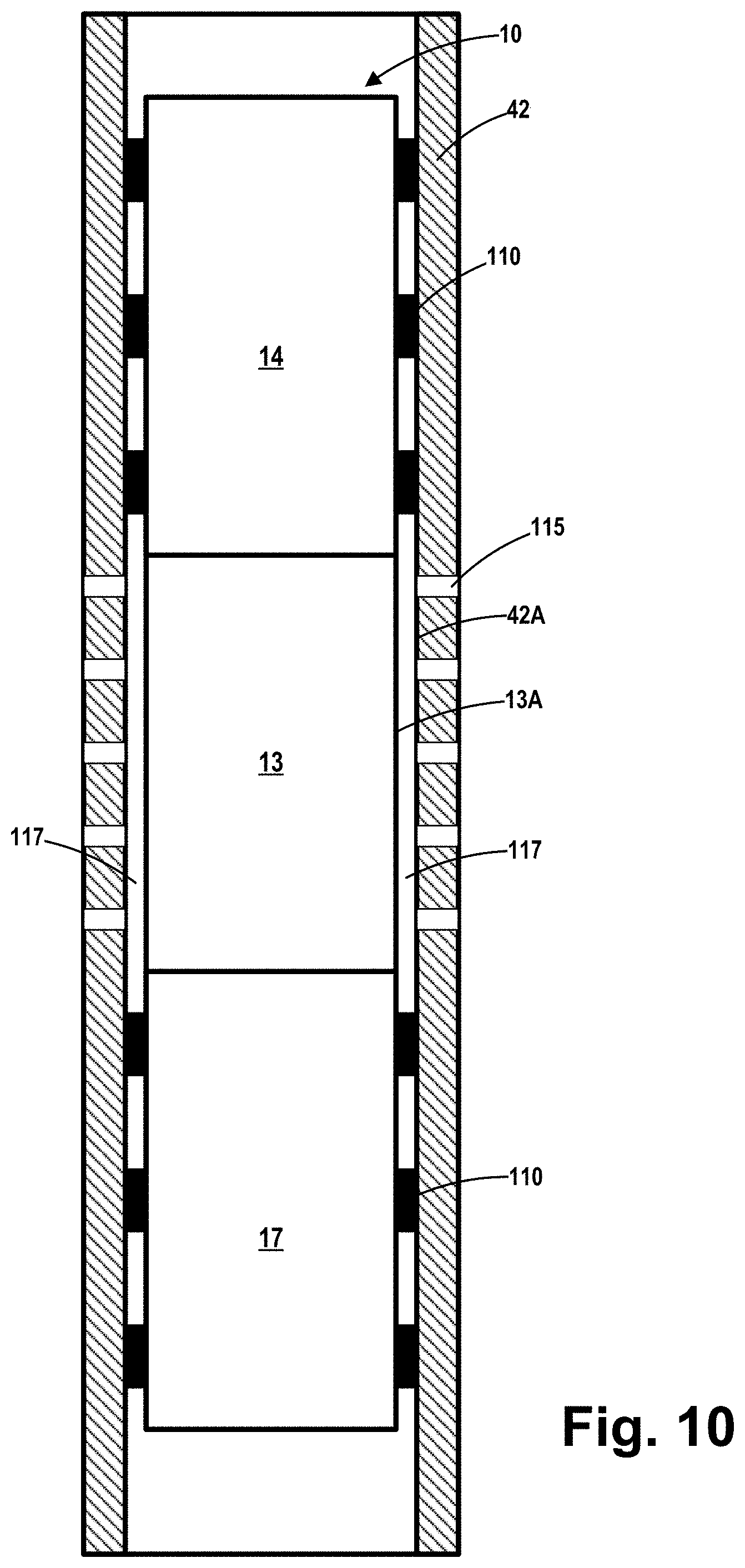
[0030] FIG. 10 is a simplistic depiction of an embodiment of the apparatus 10 disclosed herein after the expandable sections 14B, 17B of the tubulars 14, 17, respectively, have been expanded such that the elastomer bands 110 engage the inner surface 42A of the illustrative pre-existing casing 42. Certain components of the apparatus 10, e.g., the clad release sub 12 that is located above the tubular 14 and the guide nose 26 that is located below the tubular 17 are not depicted in FIG. 10. In this illustrative example, the existing casing 42 within the wellbore comprises a plurality of simplistically depicted perforations 115 that will be effectively covered by the intermediate casing 13. As noted above, in the example depicted herein, the intermediate casing 13 does not undergo any appreciable radial expansion as the expandable sections 14B, 17B of the tubulars 14, 17, respectively, expand. Thus, at the completion of the expansion process, there will be a radial gap 117 between the inside surface 42A of the existing casing 42 and the outer surface 13A of the intermediate casing 13. However, the magnitude of this radial gap 117 may be relatively small depending upon the particular application, e.g., about 0.125 inches in some cases. As a result, after the expansion process is completed, the intermediate casing 13 covers the perforations 115 in the pre-existing casing 42. Thereafter, the removable portions of the apparatus 10 may be removed from the well and/or left in the bottom of the well as described more fully below. At that point, traditional fracking tools and techniques may be used to form perforations (not shown) in portions of the casing 42 above the tubular 14 or below the tubular 17.
[0031] FIG. 11 depicts an embodiment similar to that shown in FIG. 10, except in this case the apparatus 10 has been used to install the intermediate casing 13 in the area of the existing casing 42 where some erosion or loss of the casing material (as referenced by the numeral 119, has occurred. Note that, in this application, the portion of the existing casing 42 covered by the intermediate casing 13 does not contain any fracture perforations.
[0032] As will be appreciated by those skilled in the art after a complete reading of the present application, the apparatus disclosed herein is not limited to the particular application wherein expandable tubulars (e.g., 14 and 17) are positioned on opposite sides of an intermediate casing 13 that does not undergo any appreciable expansion. For example, with reference to FIG. 12, in one illustrative embodiment, the apparatus 10 may only comprise a single tubular member 14 (that may be comprised of one or more sections of pipe) that is adapted to be positioned within a wellbore and expanded to engage an existing casing 42 or the formation (in the situation of an uncased well). Also note that the clad release sub 12 and guide shoe 26 have been simplistically depicted in FIG. 12. As depicted, in this embodiment, the expansion cone 16 is forced through the entirety of the tubular 14 to cause the tubular 14 to radially expand. Thus, at the completion of the expansion process, the expanded tubular 14 covers the perforations 115 in the casing 42. Relative to the embodiment shown in FIG. 10, in the embodiment shown in FIG. 12, the guide shoe 26 is operatively coupled to the lower end of the tubular 14.
[0033] One illustrative embodiment of a method disclosed herein will be discussed in the context of FIGS. 13-20. These figures schematically depict a method that involves use of the illustrative apparatus 10 shown in FIG. 1, wherein the apparatus 10 comprises the clad release sub 12, the expandable tubular 14, the intermediate tubular string or casing 13, the expandable tubular 17 and the illustrative guide nose 26. Also schematically depicted in these drawings is what may be referred to as some of the components of a traveling expander assembly 99 that may include, among other things, the combination of the expansion cone 16 that is coupled to the upper end of the cone mandrel 18 and the float collar 24 that is operatively coupled to the lower end of the cone mandrel 18. As noted above, this traveling expander assembly 99 may comprise fewer or more components than those mentioned immediately above. The float collar 24 comprises the above-described inverted check valve 25. Of course, as noted above, the methods and devices disclosed herein may be employed to expand a single expandable liner 14 within a wellbore, as simplistically depicted in FIG. 12.
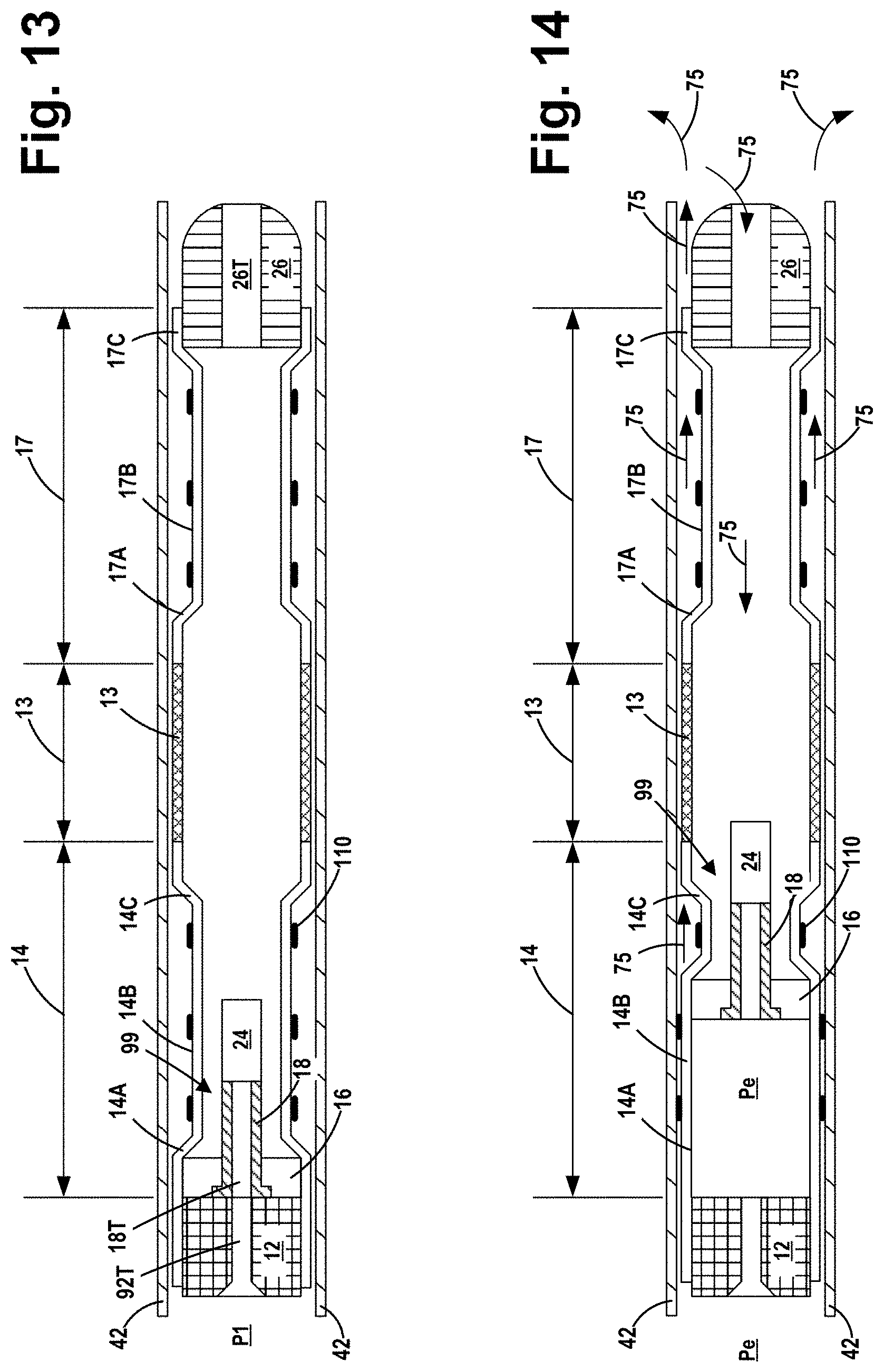
[0034] At the point shown in FIG. 13, the apparatus 10 is depicted at a point where the apparatus has been positioned in a well at a desired location within a pre-existing casing 42 that was previously positioned in the well. As noted above, the casing 42 may have a plurality of perforations (not shown). In other applications, the casing 42 may not be present and the apparatus 10 may be employed to expand the tubulars 14, 17 against the formation. There will typically be formation fluids in the well prior to the point in time where the apparatus 10 is initially run down-hole. The apparatus 10 will typically be lowered into the well with a relatively low pressure (P1) in the drill string (not shown) above the clad release sub 12. The pressure P1 may be relatively low so as to permit existing formation fluid to flow in the up-hole direction through the inverted check valve 25, thereby allowing the apparatus 10 to be lowered into position without having to force the apparatus 10 down-hole against a column of formation fluid within the well. Note that, in this initial position, the expansion cone 16 of the expander assembly 99 is positioned within the pre-expanded housing section 14A of the upper tubular 14. At this point, the expansion cone 16 has not been used to expand any portion of the tubular 14.
[0035] FIG. 14 depicts the apparatus 10 after an expansion pressure (Pe) was applied above the expansion assembly 99 thereby tending to force the expansion assembly 99 downward within the well. As indicated, the expansion cone 16 portion of the traveling expander assembly 99 has moved a portion of the way through the expandable tubular 14 thereby causing radial expansion of a portion of the axial length of the expandable tubular 14. Note that some of the elastomer bands 110 on the tubular 14 have been forced or urged into engagement with the inner surface of the existing casing 42. The inverted check valve 25 in the float collar 24 is in the closed position and thereby retains the expansion pressure (Pe) above the traveling expander assembly 99. The absolute value of the expansion pressure (Pe) may vary depending upon the particular application. In general, the expansion pressure (Pe) is of sufficient magnitude so as to force the expansion cone 16 (part of the traveling expander assembly 99) to travel down-hole and thereby expand the expandable tubulars 14, 17. Note that, during this top-down (up-hole to down-hole) tubular expansion process, there will be some existing wellbore fluid 75 (which may include formation fluids and/or other fluids added to the well and/or water) in the annular spaces (or gap) between the outer surfaces of the tubulars 14, 13 and 17 and the inner surface of the existing casing 42. There will also be some of these existing wellbore fluids 75 in the annular space (or gap) between the outer surface of the tubular 17 and the inner surface of the existing casing 42. As the expansion of the tubular 14 continues, the wellbore fluids 75 in these annular spaces that is displaced by the expansion process will be forced out of these annular spaces and flow in a down-hole direction toward the bottom or end of the well, as indicated by the arrow associated with the numeral 75. In some applications, the wellbore fluids 75 forced out from the annular spaces may flow upward through the opening or bore 26T in the guide nose 26. If that were to occur, in almost all situations, the expansion pressure (Pe) applied above the inverted check valve 25 will be greater than the pressure below the inverted check valve 25 (due to the flow of the forced wellbore fluids 75), thereby insuring that none of the displaced wellbore fluids 75 will flow upward through the inverted check valve 25 in the float collar 24. Rather, these displaced wellbore fluids will flow out into the formation at some location below the expanded tubular 17 (in this particular example of the apparatus). That is, the wellbore fluids 75 displaced by the expansion process may flow outwardly into the formation via one or more perforations (not shown) formed in the existing casing 42 below the location of the apparatus and/or into an open-hole portion of the well below any cased portion of the well. Of course, in the case of a non-cased well, these displaced wellbore fluids may simply be forced into the formation at some point below the apparatus. This is a unique aspect of the methods and systems disclosed herein as compared to prior art methods and systems where wellbore fluids displaced by a tubular expansion process were typically returned to the surface via an annular flow path in the well.
[0036] FIG. 15 depicts the apparatus 10 at a later point in the process wherein the expansion cone 16 portion of the traveling expander assembly 99 has moved to a location within the intermediate casing 13. As indicated, expansion pressure (Pe) is still applied above the traveling expander assembly 99.
[0037] FIG. 16 depicts the apparatus 10 at a later point in the process wherein the expansion cone 16 portion of the traveling expander assembly 99 has moved a portion of the way through the expandable tubular 17 thereby causing radial expansion of a portion of the axial length of the expandable tubular 17. As indicated, expansion pressure (Pe) is still applied above the traveling expander assembly 99. Note that, at this point in the process flow, the bottom of the float collar 24 is at a location where it is about to contact the upper surface of the guide nose 26.
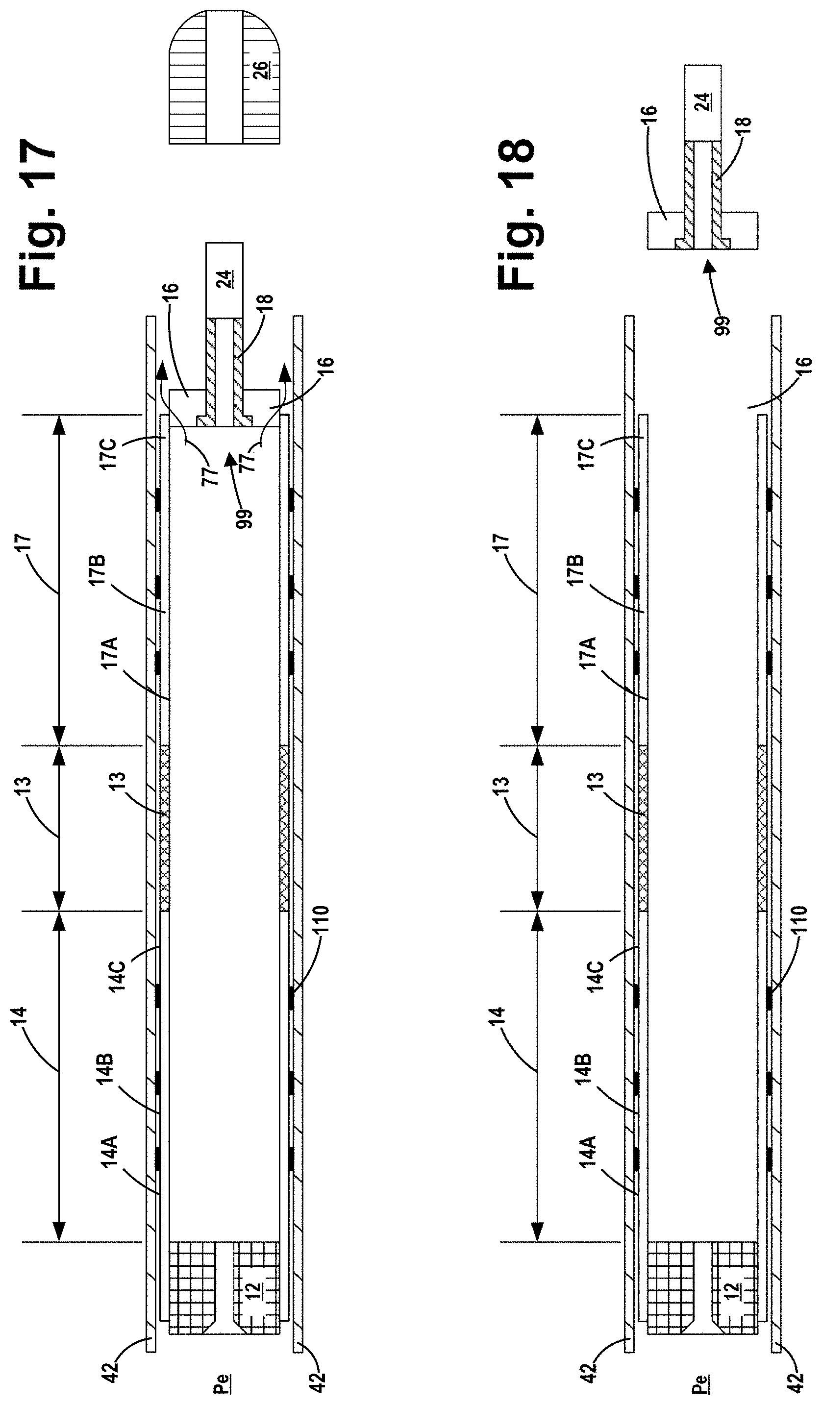
[0038] FIG. 17 depicts the apparatus after several actions were taken. First, the traveling expander assembly 99 was urged further downward so as to cause the float collar 24 to engage the guide nose 26 and thereby cause the shear pin connection between the guide nose 26 and the lower end of the tubular 17 to be broken. This action releases the guide nose 26 and, in one embodiment, allows the guide nose 26 to simply fall toward the bottom or end of the well. The force applied to break the shear pin connection between the guide nose 26 and the tubular 17 may be applied by simply applying additional weight to the apparatus 10 by controlling known lift mechanisms at the surface. This shearing force could also be applied by increasing the pressure above the traveling expander assembly 99, but such an increase in pressure could lead to an abrupt separation of the guide nose from the tubular 17. Next, after the guide nose is released, expansion pressure (Pe) is continued to be applied above the traveling expander assembly 99 so as to cause expansion of the entirety of the tubular 17. The expansion cone 16 continues to travel downward until such time as the lip seal 28 (see FIG. 6) on the expansion cone 16 moves past the lower end of the tubular 17. At that point, internal pressure within the tubular 17 above the traveling expander assembly 99 is released to the well, as indicated by the arrows 77.
[0039] FIG. 18 depicts the apparatus 10 after the traveling expander assembly 99 has fully exited the lower tubular 17. In one embodiment, the traveling expander assembly 99 is simply allowed to fall toward the bottom or end of the well. The guide nose 26 is not depicted in FIG. 18.
[0040] FIG. 19 depicts the apparatus 10 after a drop ball 80 has landed in the shear sleeve 92 (not separately shown--see FIG. 7) in the clad release sub 12. At that point, the pressure above the clad release sub 12 is increased to a pressure (Ps) sufficient to cause the shear pins 94 to shear thereby releasing the sleeve 92 to travel downward within the bore 12T of the clad release sub 12. The travel of the sleeve 92 continues until it stops on the shoulder 12X. At that time, recesses 104 in the outer surface of the sleeve 92 are aligned with the inwardly biased spring-loaded dogs 100. The spring-loaded dogs 100 extend inwardly to engage the recesses 104 thereby preventing any further relative axial movement between the sleeve 92 and the clad release sub 12. When the sleeve 92 has shifted to the position where it engages the shoulder 12X, the upper surface 92S of the sleeve 92 is positioned down-hole of the openings 90 that extend through the body of the clad release sub 12.
[0041] FIG. 20 depicts the apparatus wherein the clad release sub 12 is lifted completely free of tubular 14 by upward movement of the deployment string (not shown) that is coupled to the clad release sub 12. The clad release sub 12 may be retrieved to the surface. To the extent there are any fluids in the deployment string, those fluids may drain from the deployment string into the well via the openings 90 in the clad release sub 12.
[0042] The unique configuration of the apparatus disclosed herein also permits continued operations under sometimes unique and unexpected operating situations. For example, during the process of supplying expansion pressure (Pe) above the traveling expander assembly 99 so as to cause expansion of the tubular 14 and/or 17, and thereby forcing the displaced wellbore fluids into the formation below the apparatus, the pressure below the inverted check valve 25 might, under some circumstances, become relatively large. One option would to be to continually increase the magnitude of the expansion pressure (Pe) so as to keep the inverted check valve 25 closed and continue to drive the traveling expander assembly 99 downward through the tubulars 14, 17. However, depending on the pressure differential across the inverted check valve 25 (which is also present across the expansion cone 16), the rate of travel of the traveling expander assembly 99 may become relatively slow, thereby increasing the time required for the expansion process to be completed. Additionally, continuing to increase the expansion pressure (Pe) can require larger and more expensive pumping equipment.
[0043] However, due to the unique inverted check valve 25 in the float collar 24 herein, when it is determined that the expansion pressure (Pe) is required to be larger than desired due to an increase in pressure below the inverted check valve 25 (hereinafter the formation pressure), various actions may be taken to alleviate this condition. For example, the formation pressure may be reduced by reducing the pressures above the traveling expander assembly 99 to a very small value, thereby allowing fluid below the inverted check valve 25 to flow upward through the inverted check valve 25, the cone mandrel 18, the clad release sub 12 and the deployment string to the surface. This process can be continued until such time as formation pressure below the inverted check valve 25 is within acceptable limits. At that time, the pressure above the traveling expander assembly 99 may again be increased to the desired expansion pressure (Pe) and the expansion of the tubular 14 and/or 17.
[0044] As noted above, in one illustrative embodiment, the traveling expander assembly 99 may simply be left at the bottom of the well or it may be retrieved to the surface depending upon the requirements of the well and/or operator preference. In an alternative embodiment of the system, the top of the cone mandrel 18 may be configured for retrieval by the use of conventional fishing equipment. In yet another embodiment, a latch (not shown) may be provided at the lower end of the cone mandrel 18 that mates with the guide nose 26 after or near the end of the expansion operation. For example, the guide nose 26 may be provided with a receptacle (not shown) for the latch and a releasable connection to the mandrel 18 so that once the guide nose 26 is latched to the mandrel 18, the combination of the traveling expander assembly 99 and guide nose 26 may be retrieved to the surface in one trip.
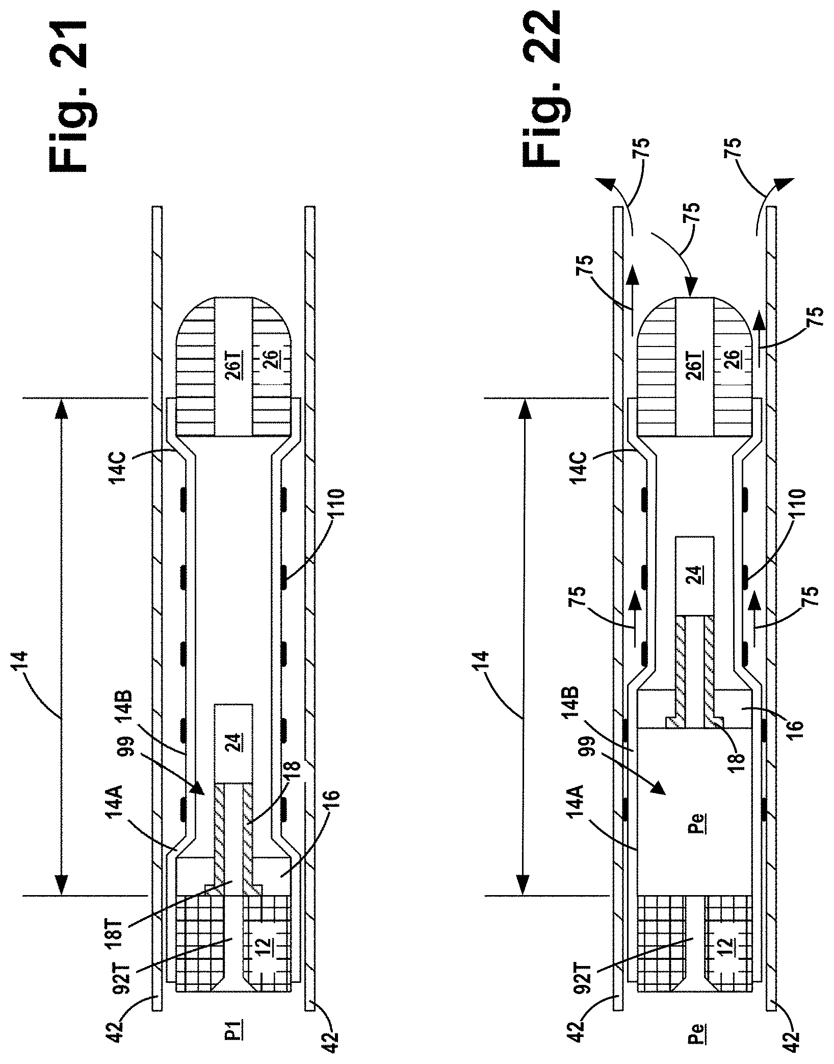
[0045] FIGS. 21-26 depict one illustrative method that corresponds to the methods described above in the context of FIGS. 13-20. However, in FIGS. 21-26 the system was employed to expand one single tubular 14 within the wellbore, instead of the two expandable tubulars 14, 17 shown in FIGS. 13-20. Of course, as before, the tubular 14 may itself be comprised of a single section of pipe or multiple sections of pipe coupled together. FIG. 21 corresponds to the situation depicted in FIG. 13 above, i.e., at a point in the process where the apparatus has been positioned in a well at a desired location within a pre-existing casing 42. FIG. 22 corresponds to the situation depicted in FIG. 14, i.e., after the expansion pressure (Pe) was applied above the expansion assembly 99 thereby tending to force the expansion assembly 99 downward within the well. As indicated, the expansion cone 16 portion of the traveling expander assembly 99 has moved a portion of the way through the expandable tubular 14 thereby causing radial expansion of a portion of the axial length of the expandable tubular 14.
[0046] FIG. 23 corresponds to the situation depicted in FIG. 16 wherein the traveling expander assembly 99 has moved further down through the expandable tubular 14 to the point where the bottom of the float collar 24 is at a location where it is about to contact the upper surface of the guide nose 26. FIG. 24 depicts the situation corresponding to FIG. 17 wherein the traveling expander assembly 99 was urged further downward so as to cause the float collar 24 to engage the guide nose 26 and thereby cause the shear pin connection between the guide nose 26 and the lower end of the tubular 17 to be broken. As before, this action releases the guide nose 26 and, in one embodiment, allows the guide nose 26 to simply fall toward the bottom or end of the well. As before, the expansion cone 16 continues to travel downward until such time as the lip seal 28 (see FIG. 6) on the expansion cone 16 moves past the lower end of the tubular 14. At that point, internal pressure within the tubular 14 above the traveling expander assembly 99 is released to the well, as indicated by the arrows 77. FIG. 25 depicts the situation corresponding to FIG. 18, i.e., after the traveling expander assembly 99 has fully exited the lower tubular 14. In one embodiment, the traveling expander assembly 99 is simply allowed to fall toward the bottom or end of the well. The guide nose 26 is not depicted in FIG. 25. FIG. 26 depicts the apparatus after the steps shown in FIGS. 19 and 20 were taken, e.g., after the drop ball 80 has landed in the shear sleeve 92 in the clad release sub 12, after the pressure above the clad release sub 12 was increased so as shear the shear pin connection between the shear sleeve 92 and the clad release sub 12 thereby allowing the shear sleeve 92 to travel downward within the bore 12T of the clad release sub 12, etc. FIG. 26 also depicts the apparatus wherein the clad release sub 12 is lifted completely free of tubular 14 by upward movement of the deployment string (not shown) that is coupled to the clad release sub 12.
[0047] The particular embodiments disclosed above are illustrative only, as the invention may be modified and practiced in different but equivalent manners apparent to those skilled in the art having the benefit of the teachings herein. For example, the process steps set forth above may be performed in a different order. Furthermore, no limitations are intended to the details of construction or design herein shown, other than as described in the claims below. It is there-fore evident that the particular embodiments disclosed above may be altered or modified and all such variations are considered within the scope and spirit of the invention. Note that the use of terms, such as "first," "second," "third" or "fourth" to describe various processes or structures in this specification and in the attached claims is only used as a shorthand reference to such steps/structures and does not necessarily imply that such steps/structures are performed/formed in that ordered sequence. Of course, depending upon the exact claim language, an ordered sequence of such processes may or may not be required. Accordingly, the protection sought herein is as set forth in the claims below.
* * * * *
D00000
D00001
D00002
D00003
D00004
D00005
D00006
D00007
D00008
D00009
D00010
D00011
D00012

D00013
D00014

D00015
D00016

D00017
D00018

D00019

XML
uspto.report is an independent third-party trademark research tool that is not affiliated, endorsed, or sponsored by the United States Patent and Trademark Office (USPTO) or any other governmental organization. The information provided by uspto.report is based on publicly available data at the time of writing and is intended for informational purposes only.
While we strive to provide accurate and up-to-date information, we do not guarantee the accuracy, completeness, reliability, or suitability of the information displayed on this site. The use of this site is at your own risk. Any reliance you place on such information is therefore strictly at your own risk.
All official trademark data, including owner information, should be verified by visiting the official USPTO website at www.uspto.gov. This site is not intended to replace professional legal advice and should not be used as a substitute for consulting with a legal professional who is knowledgeable about trademark law.