Baluster Shoes
Calderone; Anthony B. ; et al.
U.S. patent application number 16/801446 was filed with the patent office on 2020-09-03 for baluster shoes. The applicant listed for this patent is Anthony B. Calderone, Effie L. Calderone. Invention is credited to Anthony B. Calderone, Effie L. Calderone.
| Application Number | 20200277793 16/801446 |
| Document ID | / |
| Family ID | 1000004747809 |
| Filed Date | 2020-09-03 |


| United States Patent Application | 20200277793 |
| Kind Code | A1 |
| Calderone; Anthony B. ; et al. | September 3, 2020 |
Baluster Shoes
Abstract
An adjustable shoe has a first part and a second part with respective bodies with inner, outer, top, and bottom surfaces. The second part is attachable to first part to define an opening itself defining a central axis and being configured for receiving the baluster therethrough. The opening is configured so that the first part and the second part may be adjustably attached to the baluster with compensation for any misalignment of the baluster and the mounting surface. The adjustable shoe may include only one of the first parts and only one of the second parts, each extending about 180 degrees around the central axis. If so, the only one first part and the only one second part may be identical, and/or generally L-shaped when viewed along a line parallel to the central axis. A related assembly includes an adjustable shoe and a baluster.
| Inventors: | Calderone; Anthony B.; (Simpsonville, SC) ; Calderone; Effie L.; (Simpsonville, SC) | ||||||||||
| Applicant: |
|
||||||||||
|---|---|---|---|---|---|---|---|---|---|---|---|
| Family ID: | 1000004747809 | ||||||||||
| Appl. No.: | 16/801446 | ||||||||||
| Filed: | February 26, 2020 |
Related U.S. Patent Documents
| Application Number | Filing Date | Patent Number | ||
|---|---|---|---|---|
| 62811678 | Feb 28, 2019 | |||
| Current U.S. Class: | 1/1 |
| Current CPC Class: | E04F 11/1814 20130101; E04F 11/1834 20130101 |
| International Class: | E04F 11/18 20060101 E04F011/18 |
Claims
1. An adjustable shoe for a baluster attached to a mounting surface and having a longitudinal axis and cross-section of a predetermined size, the adjustable shoe comprising: a first part having a body with an inner surface, an outer surface, a top surface, and a bottom surface; and a second part having a body with an inner surface, and outer surface a top surface and a bottom surface, the second part attachable to first part to define an opening between the at least a portion of the inner surfaces of the first part and the second part, the opening defining a central axis and being configured for receiving the baluster therethrough, the opening being configured so that the first part and the second part may be adjustably attached to the baluster with the central axis and the longitudinal axis at an angle of up to about 10 degrees to compensate for any misalignment of the baluster and the mounting surface.
2. The adjustable shoe of claim 1, wherein the at least a portion of the inner surfaces of the first part and the second part include a wall parallel to the central axis.
3. (canceled)
4. (canceled)
5. The adjustable shoe of claim 2, wherein the angle between the central axis and the longitudinal axis is about 8 degrees.
6. The adjustable shoe of claim 1, wherein the at least a portion of the inner surfaces of the first part and the second part include a wall non-aligned with the central axis so as to form a frustum.
7. (canceled)
8. (canceled)
9. The adjustable shoe of claim 6, wherein the angle between the central axis and the longitudinal axis is about 8 degrees.
10. The adjustable shoe of claim 6, wherein the angle between the central axis and the wall is about 8 degrees.
11. (canceled)
12. The adjustable shoe of claim 1, wherein the first part and the second part are removably attachable to each other.
13. The adjustable shoe of claim 12, wherein the first part and second part have cooperating tabs and slots for removable attachment via sliding in a direction along the central axis.
14. (canceled)
15. (canceled)
16. The adjustable shoe of claim 1, further including a cap attachable to the top surfaces of the first part and the second part.
17. The adjustable shoe of claim 16, wherein the top surfaces of the first part and the second part define a recess for receiving the cap in a snap fit.
18. The adjustable shoe of claim 16, wherein the cap defines an opening sized for receipt of the baluster therethrough.
19. (canceled)
20. The adjustable shoe of claim 16, wherein the cap is formed of a resiliently deformable material.
21. The adjustable shoe of claim 16, wherein the cap on one hand and the first part and the second part on the other hand are sized for frictional engagement wherein upon assembly the cap is secured to the first part and the second part thereby and the first part and the second part are secured to the baluster thereby.
22-24. (canceled)
25. The adjustable shoe of claim 1, wherein the adjustable shoe includes only one of the first parts and only one of the second parts, the only one first part and the only one second part each extending about 180 degrees around the central axis.
26. The adjustable shoe of claim 25, wherein the only one first part and the only one second part are identical.
27. The adjustable shoe of claim 25, the only one first part and the only one second part are generally L-shaped when viewed along a line parallel to the central axis.
28-30. (canceled)
31. An adjustable shoe for a baluster attached to a mounting surface and having a longitudinal axis and cross-section of a predetermined size, the adjustable shoe comprising: a first part having a body with an inner surface, an outer surface, a top surface, and a bottom surface; a second part having a body with an inner surface, and outer surface a top surface and a bottom surface, the second part attachable to first part to define an opening between the at least a portion of the inner surfaces of the first part and the second part, the opening defining a central axis and being configured for receiving the baluster therethrough, the opening being configured so that the first part and the second part may be adjustably attached to the baluster with the central axis pivotable relative to the longitudinal axis to compensate for any misalignment of the baluster and the mounting surface; and a cap attached to the top surfaces of the first part and the second part and around the baluster, the cap defining an opening sized for receipt of the baluster therethrough, the cap being formed of a resiliently deformable material softer than the first part, the second part, and the baluster so that the cap secures the first part and the second part to the baluster.
32-36. (canceled)
37. The adjustable shoe of claim 31, wherein the adjustable shoe includes only one of the first parts and only one of the second parts, the only one first part and the only one second part each extending about 180 degrees around the central axis.
38. The adjustable shoe of claim 37, wherein the only one first part and the only one second part are identical.
39. The adjustable shoe of claim 37, the only one first part and the only one second part are generally L-shaped when viewed along a line parallel to the central axis.
Description
CROSS-REFERENCE TO RELATED APPLICATION
[0001] The present application is a Non-Provisional patent application and claims priority to U.S. Provisional Patent Application Ser. No. 62/811,678, filed Feb. 28, 2019, which is incorporated by reference herein.
TECHNICAL FIELD
[0002] The present disclosure relates generally to shoes for balusters, and in some aspects relates to adjustable baluster shoes.
BACKGROUND
[0003] Handrails, safety railings and the like are often supported by a number of spaced-apart vertical members often called balusters. Balusters may be uniformly square or rounded in cross-section along their lengths, may vary in cross-section along their lengths, and/or may include decorative elements that differ from other more linear portions along their lengths. Balusters may be made of wood, metal, stone, plastic, etc., or combinations of materials.
[0004] Balusters are attached at a bottom end to a mounting surface, which could be a horizontal or angled relative to horizontal footing, stair step, floor surface or other surface. Balusters are attached at a top end to a mounting surface such as a handrail, railing, etc., which again may be horizontal or angled relative to horizontal.
[0005] Often "shoes" that surround a baluster are used to cover imperfections, mounting holes, etc., and/or add decorative appeal to the point of connection between the ends of the balusters and the top or bottom mounting surfaces. However, existing shoes that are single pieces cannot be attached after installation of a baluster. Also, many balusters are made with ends in standard sizes for modular use in the building and renovation industry (e.g., 0.25, 0.375, 0.5, 0.75, 1.0, 1.25 inch, etc., squares or diameters, or similar ranges of metric sizing). If sizing of the shoes (i.e., the openings for receiving the balusters) is closely selected to match the sizing of the balusters, and if balusters are installed with slight variation to desired orientation (i.e., skewed slightly from vertical), the shoes may not sit with bottom surfaces aligned with the mounting surface producing gaps between the baluster shoe and the mounting surface and or the baluster. Such gaps can sometimes be produced in baluster shoes secured to balusters by set screws, where tightening of the set screw causes such a misalignment of the shoe relative to the surface(s) adjacent the baluster end(s).
[0006] Accordingly, a baluster shoe that addresses one or more drawbacks of existing baluster shoes or one or more of the above issues, that is readily manufactured and installed, that is cost effective, and/or that addresses any other issues would be welcome.
SUMMARY
[0007] According to certain aspects of the disclosure, an adjustable shoe is disclosed for a baluster attached to a mounting surface and having a longitudinal axis and cross-section of a predetermined size, the adjustable shoe including, for example, a first part having a body with an inner surface, an outer surface, a top surface, and a bottom surface; and a second part having a body with an inner surface, and outer surface a top surface and a bottom surface. The second part is attachable to first part to define an opening between the at least a portion of the inner surfaces of the first part and the second part, the opening defining a central axis and being configured for receiving the baluster therethrough. The opening is configured so that the first part and the second part may be adjustably attached to the baluster with the central axis and the longitudinal axis at an angle of up to about 10 degrees to compensate for any misalignment of the baluster and the mounting surface. Various options and modifications are possible.
[0008] For example, at least a portion of the inner surfaces of the first part and the second part include a wall parallel to the central axis. If so, the wall may include four walls arranged so that a cross-section perpendicular to the central axis is a square, or the wall may be annular. The angle between the central axis and the longitudinal axis may be about 8 degrees.
[0009] At least a portion of the inner surfaces of the first and second parts may include a wall non-aligned with the central axis so as to form a frustum. If so, the wall may include four walls arranged so that a cross-section perpendicular to the central axis is a square, or the wall may be annular. The angle between the central axis and the longitudinal axis of such wall may be about 8 degrees, and the angle between the central axis and the wall may be about 8 degrees.
[0010] If the shoe includes four walls, three of the walls may be on the first part and a fourth of the walls being on the second part. The first and second parts may be removably attachable to each other. The first and second parts may have cooperating tabs and slots for removable attachment via sliding in a direction along the central axis. The first part may include three detachable sections, each of the detachable sections and the second part encompassing about one quarter of the opening, and the three detachable sections and the second part may all be substantially identical.
[0011] The shoe may further include a cap attachable to the top surfaces of the first part and the second part. The top surfaces may define a recess for receiving the cap in a snap fit, and the cap may define an opening sized for receipt of the baluster therethrough, and the cap may include two sections. Also, the cap may be formed of a resiliently deformable material. The cap on one hand and the first part and the second part on the other hand may be sized for frictional engagement wherein upon assembly the cap is secured to the first part and the second part thereby and the first part and the second part are secured to the baluster thereby.
[0012] The bottom surfaces of the first and second parts may include portions substantially perpendicular to the central axis and configured for use with a substantially horizontal mounting surface, or may include portions at an angle relative to the central axis and configured for use with a substantially non-horizontal mounting surface.
[0013] An adhesive may be located on at least one of the bottom surfaces of the first part and the second part for securing the first part and the second part to the mounting surface.
[0014] The adjustable shoe may include only one of the first parts and only one of the second parts, the only one first part and the only one second part each extending about 180 degrees around the central axis. If so, the only one first part and the only one second part may be identical, and/or the only one first part and the only one second part may be generally L-shaped when viewed along a line parallel to the central axis.
[0015] An assembly may be created including the adjustable shoe and the baluster. The baluster may have a cross-section perpendicular to the longitudinal axis, wherein the cross-section is rectangular, square, or circular.
[0016] According to other aspects of the disclosure, an adjustable shoe is disclosed for a baluster attached to a mounting surface and having a longitudinal axis and cross-section of a predetermined size, the adjustable shoe includes, for example, a first part having a body with an inner surface, an outer surface, a top surface, and a bottom surface, and a second part having a body with an inner surface, and outer surface a top surface and a bottom surface. The second part is attachable to first part to define an opening between the at least a portion of the inner surfaces of the first part and the second part, the opening defining a central axis and being configured for receiving the baluster therethrough. The opening is configured so that the first part and the second part may be adjustably attached to the baluster with the central axis pivotable relative to the longitudinal axis to compensate for any misalignment of the baluster and the mounting surface. A cap is attached to the top surfaces of the first part and the second part and around the baluster. The cap defines an opening sized for receipt of the baluster therethrough. The cap is formed of a resiliently deformable material softer than the first part, the second part, and the baluster so that the cap secures the first part and the second part to the baluster. Various options and modifications are possible.
[0017] For example, the top surfaces of the first part and the second part may define a recess for receiving the cap in a snap fit. The cap may include two sections, or may include a radially extending slit from the opening to an outer edge. The first part and the second part may be configured so that the central axis is pivotable relative to the longitudinal axis by up to about 10 degrees. An adhesive may be located on at least one of the bottom surfaces of the first part and the second part for securing the first part and the second part to the mounting surface.
[0018] The adjustable shoe may include only one of the first parts and only one of the second parts, the only one first part and the only one second part each extending about 180 degrees around the central axis. If so, the only one first part and the only one second part may be identical, and/or the only one first part and the only one second part may be generally L-shaped when viewed along a line parallel to the central axis
BRIEF DESCRIPTION OF THE DRAWINGS
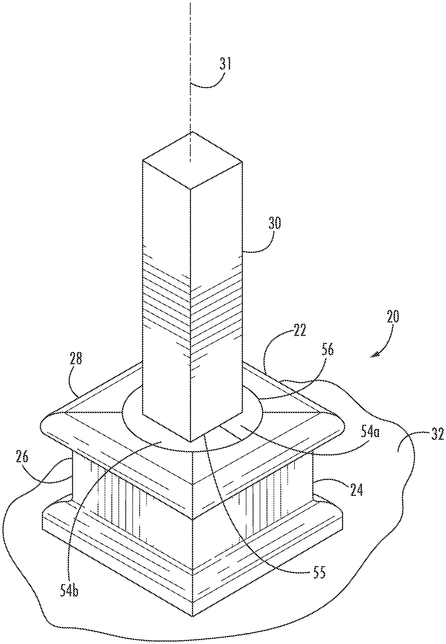
[0019] FIG. 1 is a close-up perspective view of a six-part baluster shoe installed along an adjacent horizontal lower mounting surface.
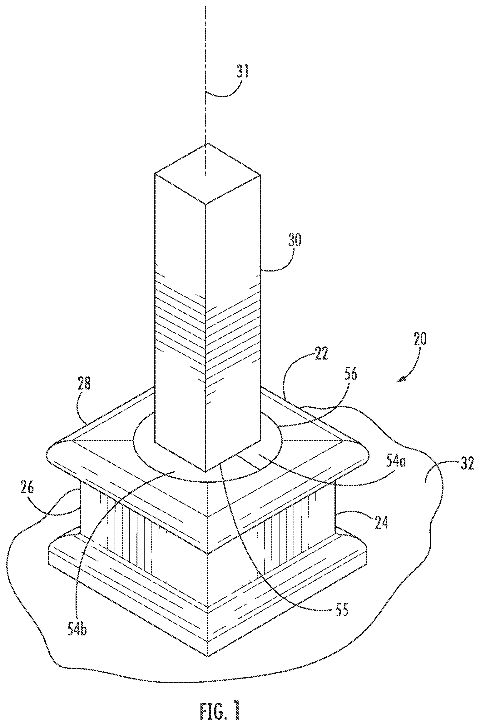
[0020] FIG. 2 is an exploded perspective view of the baluster shoe as in FIG. 1.
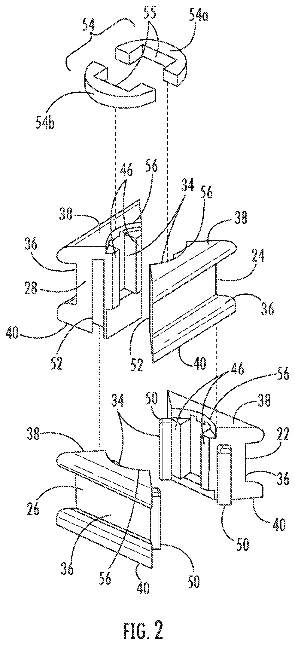
[0021] FIG. 3 is a side view of baluster shoes placed at tops and bottoms of balusters installed along horizontal upper and lower mounting surfaces.
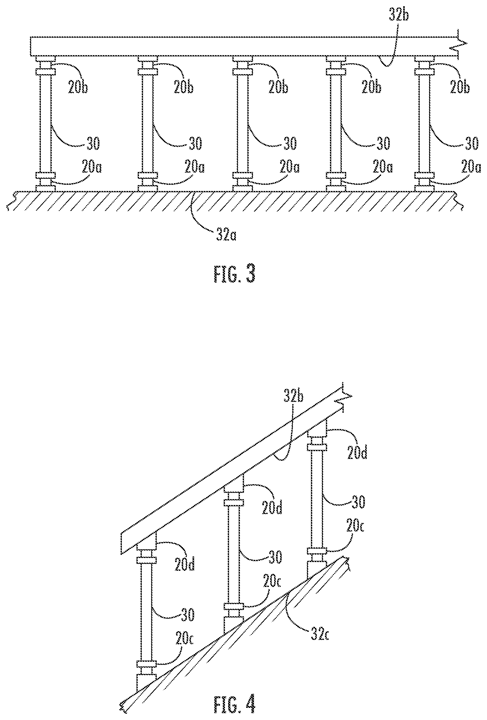
[0022] FIG. 4 is a side view of baluster shoes placed at tops and bottoms of balusters installed along non-horizontal upper and lower mounting surfaces.
[0023] FIG. 5 is an exaggerated diagrammatical sectional view showing adjustability of the baluster shoe as in FIG. 1 relative to the baluster and/or mounting surface.
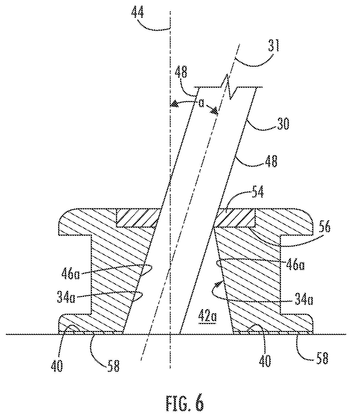
[0024] FIG. 6 is an exaggerated diagrammatical sectional view as in FIG. 5, with an alternate baluster configuration.
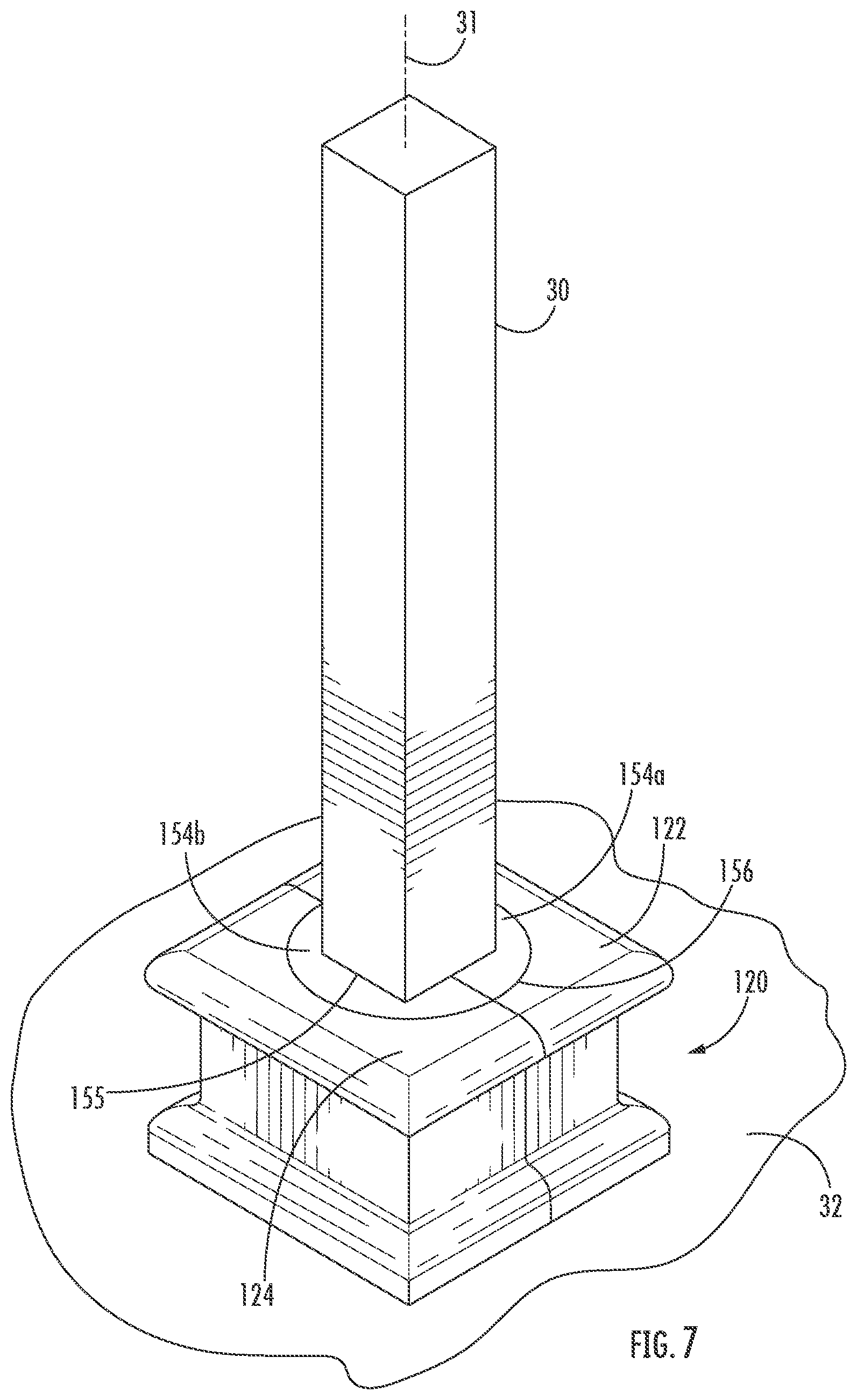
[0025] FIG. 7 is a close-up perspective view of a modified four-part baluster shoe installed along an adjacent horizontal lower mounting surface.
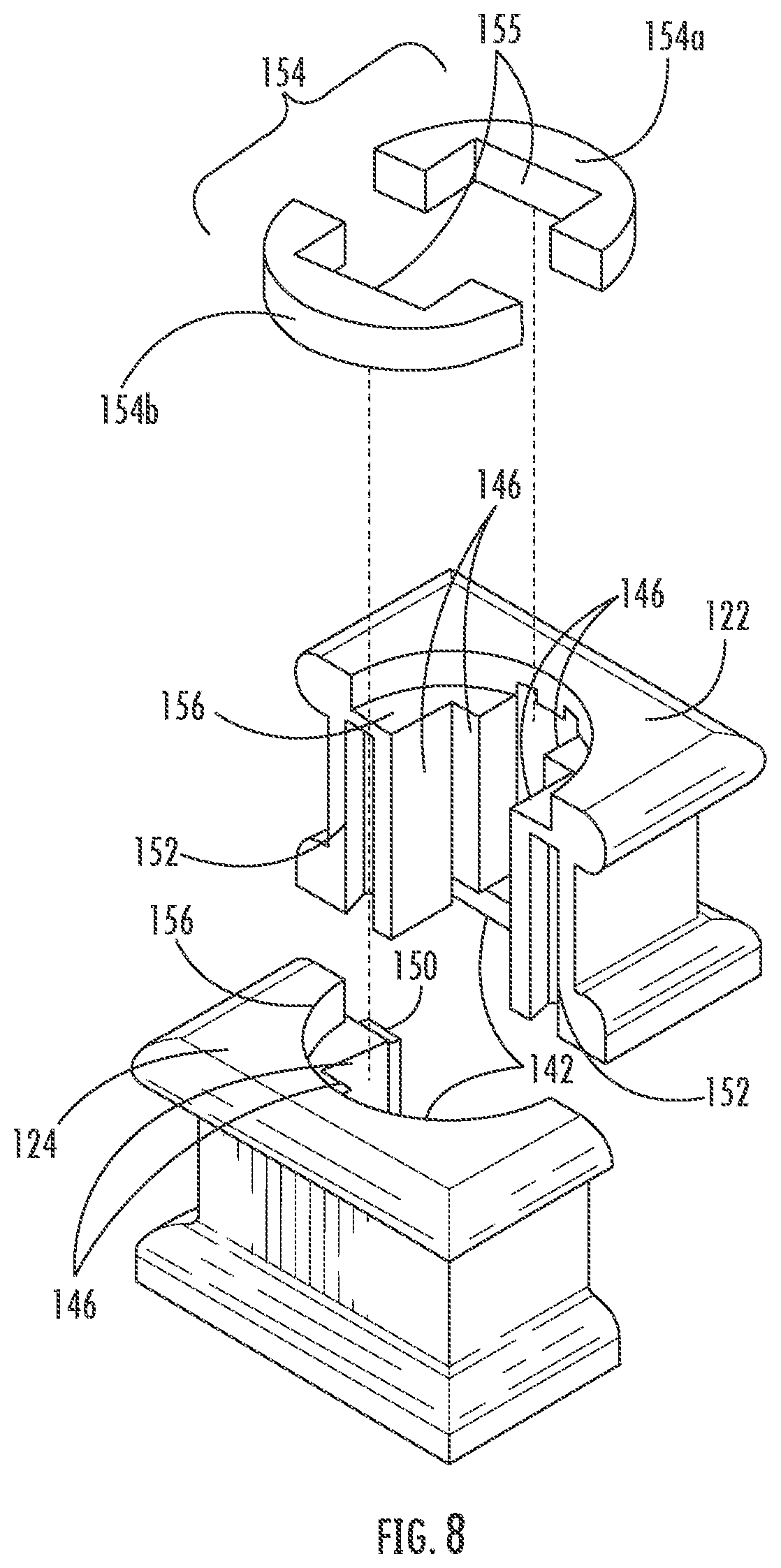
[0026] FIG. 8 is an exploded perspective view of the baluster shoe as in FIG. 7.
[0027] FIG. 9 is a close-up perspective view of another modified four-part baluster shoe installed along an adjacent non-horizontal lower mounting surface.
DETAILED DESCRIPTION
[0028] Detailed reference will now be made to the drawings in which examples embodying the present disclosure are shown. The detailed description uses numeral and letter designations to refer to features in the drawings. Like or similar designations in the drawings and description have been used to refer to like or similar parts of the disclosure.
[0029] The drawings and detailed description provide a full and enabling description of the disclosure and the manner and process of making and using it. Each embodiment is provided by way of explanation of the subject matter not limitation thereof. In fact, it will be apparent to those skilled in the art that various modifications and variations may be made to the disclosed subject matter without departing from the scope or spirit of the disclosure. For instance, features illustrated or described as part of one embodiment may be used with another embodiment to yield a still further embodiment.
[0030] Generally speaking, the Figures depict several examples of adjustable shoes for a baluster and attachable to a mounting surface (either upper or lower). The adjustable shoes are made of more than one part and can be assembled around the baluster after installation of the baluster, and thus need not be placed on (i.e., slid onto) the baluster before the baluster is secured to the mounting surfaces. The shoes are adjustable within a range allowing for secure, decorative placement that takes into account minor misalignment between the baluster and mounting surface (upper or lower) to which the baluster is connected. The adjustable shoes can be configured to be mounted adjacent horizontal surfaces or sloped surfaces, at upper or lower ends of balusters. A flexible, resilient, and/or frictional fit of some sort, and/or an adhesive, may be used to hold the adjustable shoe in place adjacent the mounting surface.
[0031] As shown, baluster shoe 20 of FIGS. 1 and 2 includes multiple (four) parts 22, 24, 26, and 28 that surround baluster 30 for placement adjacent mounting surface 32. Baluster 30 has a central longitudinal axis 31 therethrough adjacent mounting surface 32 where shoe 20 will be located.
[0032] Mounting surface 32 as shown is horizontal and is a lower surface, but it could be an upper surface and/or non-horizontal as well. Thus, as shown in FIG. 3, baluster shoes 20 may be installed in locations as follows: shoes 20a for mounting on a bottom horizontal surface 32a or shoes 20b for mounting on a top horizontal surface 32b. FIG. 4 shows alternate shoe designs (discussed in more detail below), with shoes 20c and 20d respectively mounted to bottom and top non-horizontal (angled) mounting surfaces 32c and 32d.
[0033] As shown, the four parts 22-28 each extend about 1/4 of the way (about 90 degrees circumferentially) around baluster 30, with structures for interlocking with adjacent parts to form a completed shoe. As illustrated as and will be described in more detail below, the ends of parts 22-28 meet and interlock roughly at circumferential corners of the resulting generally square baluster shoe 20 around a generally square portion of baluster 30, although the interlock locations may be elsewhere around the circumference. Also, baluster shoe 20 once assembled need not be generally externally square. For example, baluster shoe 20 could be externally curved, circular, irregularly shaped, etc., in any desired fashion for functional covering of the baluster/mounting surface interface and/or design appearance.
[0034] It should be understood that in a broad sense, the invention requires only two such shoe parts. Thus, one part may be as illustrated and extend about 1/4 of the way (about 90 degrees) around baluster 30, and the other part may modified to be a unitary part extending 3/4 of the way (about 270 degrees) around, in a generally "U" shaped configuration. In other words, part 22 could remain as shown, and parts 24-28 could be combined into one U-shaped part.
[0035] Alternatively, parts 22 and 24 could be formed unitarily and parts 26 and 28 could be formed unitarily. The resulting to two parts would thus both extend about 1/2 of the way (about 180 degrees) around baluster 30 in a generally "L" shaped configuration. The resulting two parts (22+24 and 26+28) could be symmetrical and thus identical, thereby providing manufacturing, supply, and inventory efficiencies. As above, the resulting parts of such a modified shoe could be made to have differing exterior shapes for functional and/or design reasons. Other amounts of parts greater than two could be used (i.e., three) if desired for square or round balusters.
[0036] As illustrated (see FIGS. 1, 2, and 5), each part 22-28 has a body with an inner surface 34, an outer surface 36, a top surface 38, and a bottom surface 40. Therefore, the at least two parts of shoe 20 are attachable together to define an opening 42 between the at least a portion of the inner surfaces 34 of the parts 22-28. Opening 42 defines a central axis 44. Opening 42 is sized and configured for receiving baluster 30 for placement near mounting surface 32. Note that in FIG. 5, the slant of baluster 30 relative to surface 32 is exaggerated, and the width of baluster 30 is reduced compared to the width of opening 42 for illustrative purposes, as noted below.
[0037] Opening 42 is sized and configured to allow for some degree of adjustability of baluster shoe 20 relative to baluster 30 and/or mounting surface 32 to account for any potential imperfection or misalignment that may be present. For example, it may be desired to allow parts 22-28 to pivot relative to baluster 30 by an angle a of up to 10 about degrees, or more particularly about 8 degrees. Such ranges generally account for commercially acceptable minor misalignment, as opposed to for example, poor or substandard installation. Again, angle a as illustrated is substantially greater than 10 degrees, for purposes of clearer illustration of disclosed adjustability concepts. Such degree of pivot could be achieved in multiple ways.
[0038] First, parts 22-28 can be configured so that opening 42 is sized lightly larger than baluster 30 so that a relative pivoting of up to about 10 degrees, or about 8 degrees is possible. Inner surfaces 34 of parts 22-28 can be made with contact portions 46 that are generally parallel to each other and desirably to sides 48 of baluster 30 if installed perpendicularly to mounting surface 32. Such holds true whether the cross-section of baluster 30 and opening 42 is square, angular, curved, round, etc.
[0039] Alternatively or additionally, as shown in similarly exaggerated FIG. 6, parts 22-28 can be configured so that inner surfaces 34a have contact portions 46a that are not substantially parallel to each other. Thus, contact portions 46a may flare outward in a direction (downward as shown) toward mounting surface 32, for example in a frustum shape. Again, such structure can be employed regardless of the cross-sectional shape of baluster 30 and opening 42a.
[0040] To facilitate assembly of parts 22-28 around baluster 30, each part may have connecting elements, such as a cooperating tab 50 and/or slot 52. As shown, 50 tabs are provided on parts 22 and 26 and slots 52 slots are provided on parts 24 and 28 to allow for assembly via sliding and/or a snap fit in a direction generally along central axis 44. However, each of parts could have one tab and one slot if desired, so that instead of two types of parts only one type is required. Also, sliding and/or a snap fit in a direction perpendicular to central axis 44 is also possible. Again, two or more of such parts 22-28 (i.e., four identical parts, two identical L shapes, two identical U shapes, or two non-identical parts: one being a U shape, etc.) may be employed in shoe 20 with corresponding placement of such connecting elements.
[0041] If desired, a cap 54 may be provided attachable to top surfaces 38 of parts 22-28, and such cap may fit into a recess 56 in such top surfaces. Cap 54 may be made of a hard plastic or elastomer that is resiliently deformable. Cap 54 may comprise two parts 54a,54b as shown, or a single part with a slit which can be useful for attaching to balusters already in place. Cap 54 provides a cosmetic cover covering seams between parts 22-28 and the interface with baluster 30.
[0042] Cap 54 may also at least assist in securing parts 22-28 in place on baluster 30 adjacent mounting surface 32. Cap 54 may define a central opening 55 sized for snugly fitting around baluster 30 when cap is placed into recess 56. Thus, use of cap 54 to secure shoe 20 in place can eliminate the need for tools or a conventional set screw to hold shoe 20 in place, wherein a set screw might undesirably align shoe 20 with baluster 30 but not mounting surface 32. If cap 54 is used for decorative and/or securement purposes, it should therefore be configured to permit the relative adjustment of shoe 20 relative to baluster 30 up to about 10 degrees noted above. Such securement can be used on top and bottom baluster shoes 20a and 20b.
[0043] The securement can also or alternatively be provided by an adhesive 58 located between at least one bottom surface 40 and the corresponding mounting surface 32. The adhesive may be supplied separately (i.e., squeezed from a tube or the like), or may be incorporated and placed onto shoe 20 during manufacture or assembly (i.e., in the form of an adhesive or double-sided adhesive tape covered by a release paper). Again, use of an adhesive allows connection of shoe 20 to baluster 30 flush with mounting surface 32 without use of a set screw that might interfere with the desired alignment. Use of adhesive and an elastomeric cap can assist with placement, alignment, securement, and visual appeal, although both are not required in all aspects.
[0044] FIGS. 7 and 8 show an alternate embodiment of a shoe 120 having two u-shaped parts 122 and 124 and cap 154 (parts 154a and 154b and opening 155). Tabs 150 fit in slots 152 to hold shoe parts 122 and 124 together, similar as to above. Each surfaces 146 on parts 122 and 124 may extend along three sides of the resulting opening 142 to potentially contact three sides of baluster 30 when assembled thereon. The embodiment of FIGS. 7 and 8 shows that edges between parts need not be at corners of the shoe (if square), but could instead be between the corners.
[0045] FIG. 9 show another alternate embodiment of a shoe 220 having four parts 222, 224, 226, 228, and a cap 254. Shoe is essentially similar to shoe 20, except the bottom edges 242, 244, and 246 of parts 222, 224, and 226 are modified so that shoe 220 can be used on a non-horizontal surface 232 (such as 32c or 32d in FIG. 4).
[0046] While one or more preferred embodiments have been described above, it is to be understood that any and all equivalent realizations of the disclosed subject matter are included within the scope and spirit thereof. Thus, the embodiments depicted are presented by way of example only and are not intended as limitations upon the present invention. Thus, while particular embodiments have been described and shown, it will be understood by those of ordinary skill in this art that the present invention is not limited thereto since many modifications can be made. Therefore, it is contemplated that any and all such embodiments are included in the present invention as may fall within the literal or equivalent scope of the appended claims.
* * * * *
D00000
D00001
D00002
D00003
D00004
D00005
D00006
D00007
D00008
XML
uspto.report is an independent third-party trademark research tool that is not affiliated, endorsed, or sponsored by the United States Patent and Trademark Office (USPTO) or any other governmental organization. The information provided by uspto.report is based on publicly available data at the time of writing and is intended for informational purposes only.
While we strive to provide accurate and up-to-date information, we do not guarantee the accuracy, completeness, reliability, or suitability of the information displayed on this site. The use of this site is at your own risk. Any reliance you place on such information is therefore strictly at your own risk.
All official trademark data, including owner information, should be verified by visiting the official USPTO website at www.uspto.gov. This site is not intended to replace professional legal advice and should not be used as a substitute for consulting with a legal professional who is knowledgeable about trademark law.