Garbage Separator
Leavitt; Douglas Fornell ; et al.
U.S. patent application number 16/764123 was filed with the patent office on 2020-09-03 for garbage separator. This patent application is currently assigned to AS America, Inc.. The applicant listed for this patent is AS America, Inc.. Invention is credited to Nitin S. Kolekar, Douglas Fornell Leavitt, Alanna Wing Libbrecht, Verne H. Myers.
| Application Number | 20200277766 16/764123 |
| Document ID | / |
| Family ID | 1000004857679 |
| Filed Date | 2020-09-03 |


View All Diagrams
| United States Patent Application | 20200277766 |
| Kind Code | A1 |
| Leavitt; Douglas Fornell ; et al. | September 3, 2020 |
Garbage Separator
Abstract
A garbage separator system (500) is provided, the system configured to separate water from waste, garbage, and food particles as they flow down a sink drain. In some embodiments, the system includes a screw drive (508) configured to be mounted beneath the drain of a sink and to rotate to convey waste particles laterally away from the underside of the drain of the sink (e.g., toward a bin for collecting waste particles (518)) while allowing water to drain through a plurality of drainage holes in a tube encasing the screw drive.
| Inventors: | Leavitt; Douglas Fornell; (Bethlehem, PA) ; Kolekar; Nitin S.; (Piscataway, NJ) ; Myers; Verne H.; (Fort Wayne, IN) ; Libbrecht; Alanna Wing; (Seattle, WA) | ||||||||||
| Applicant: |
|
||||||||||
|---|---|---|---|---|---|---|---|---|---|---|---|
| Assignee: | AS America, Inc. Piscataway NJ |
||||||||||
| Family ID: | 1000004857679 | ||||||||||
| Appl. No.: | 16/764123 | ||||||||||
| Filed: | November 19, 2018 | ||||||||||
| PCT Filed: | November 19, 2018 | ||||||||||
| PCT NO: | PCT/US2018/061744 | ||||||||||
| 371 Date: | May 14, 2020 |
Related U.S. Patent Documents
| Application Number | Filing Date | Patent Number | ||
|---|---|---|---|---|
| 62624725 | Jan 31, 2018 | |||
| 62588901 | Nov 20, 2017 | |||
| Current U.S. Class: | 1/1 |
| Current CPC Class: | E03C 1/2665 20130101; E03C 1/264 20130101 |
| International Class: | E03C 1/264 20060101 E03C001/264; E03C 1/266 20060101 E03C001/266 |
Claims
1. A garbage separator system for separating waste particles from water in a drain of a sink, comprising: a screw conveyor configured to be mounted beneath the drain of a sink, the screw conveyor comprising: a screw drive configured to rotate to convey waste particles laterally away from the drain of the sink; a tube encasing the screw drive, wherein the tube comprises a plurality of drainage holes configured to allow water to drain out of the screw conveyor and to retain waste particles inside the screw conveyor; and a removable waste bin configured to receive waste particles conveyed by the screw conveyor.
2. The garbage separator system of claim 1, wherein the screw drive of the screw conveyor is configured to rotate about an axis of rotation that intersects a central axis of the drain of the sink.
3. The garbage separator system of claim 2, wherein the axis of rotation is perpendicular to the axis of the drain of the sink.
4. The garbage separator system of claim 2, wherein the axis of rotation forms an acute upward angle with the axis of the drain of the sink.
5. The garbage separator system of claim 1, wherein the screw conveyor comprises a proximal portion beneath the sink drain and a distal portion above the removable waste bin.
6. The garbage separator system of claim 5, wherein the tube comprises a waste opening at the distal portion of the screw conveyor above the removable waste bin.
7. The garbage separator system of claim 1, wherein: the screw conveyor comprises a middle portion between the proximal portion and the distal portion; and some or all of the plurality of drainage holes in the tube are located at the middle portion.
8. The garbage separator system of claim 1, further comprising a return manifold configured to catch water draining from some or all of the plurality of drainage holes.
9. The garbage separator system of claim 8, wherein the return manifold is configured to be coupled to a drainage pipe such that the water caught by the return manifold drains into the drainage pipe.
10. The garbage separator system of claim 1, further comprising a housing defining an opening above the screw conveyor configured to be mounted below the dram of the sink.
11. The garbage separator of claim 10, wherein the housing defines an opening configured to allow the removable waste bin to slide into and out of the housing.
12. The garbage separator of claim 10, wherein the housing is configured to direct falling waste particles toward the waste bin.
13. The garbage separator of claim 1, wherein the tube comprises a removable end portion configured to be removed to allow removal of the screw drive from the screw conveyor.
14. The garbage separator of claim 1, wherein the garbage separator is configured to be installed in an enclosure beneath a sink.
15. The garbage separator of claim 14, wherein the garbage separator is configured such that, when installed, the removable waste bin faces in a direction toward an area in front of the sink, and is removable by sliding in the direction toward the area front of the sink.
16. The garbage separator of claim 1, further comprising a movable seal configured to move between an open position in which waste particles may pass through an opening between the tube and the waste bin and a closed position in which the opening is sealed.
Description
RELATED APPLICATIONS
[0001] This application claims the benefit of U.S. Provisional Application No. 62/588,901, filed Nov. 20, 2017, and U.S. Provisional Application No. 62/624,725, filed Jan. 31, 2018, the entire contents of each of which are hereby incorporated herein by reference.
FIELD OF THE INVENTION
[0002] This relates to waste disposal systems and, particularly, to systems for separating waste particles from water in a drain of a sink.
BACKGROUND OF THE INVENTION
[0003] Small pieces of food waste such as vegetable and fruit cuttings, cereal, dish scrapings, and other food waste are regularly poured into kitchen sinks. In some sink systems, a simple strainer is provided to block food from flowing down the drain of the sink. Water passes through the strainer and down the drain while food waste particles accumulate atop the strainer. In some sink systems, a garbage disposal system is provided to chop and grind the food waste into small enough pieces to safely pass them into the sewer/septic system along with the drainage water that is run through the drain of the sink.
SUMMARY OF THE INVENTION
[0004] As discussed above, the most common systems for processing food waste poured into sinks are strainers covering the drain of the sink and garbage disposal systems integrated into the drain of the sink. However, these solutions have various drawbacks.
[0005] For strainer systems, a user must frequently reach into the drain of the sink to remove the strainer and dispose of the small amount of food waste particles that may accumulate atop the strainer before the drain becomes effectively blocked by the accumulated waste atop the strainer. While cleaning the strainer, the user must stop the flow of water in order to prevent food particles from being washed into the drain, and the user must furthermore clear the sink in order to be able to manually reach the drain. This process may be inconvenient and unhygienic.
[0006] For garbage disposal systems, damage to sewer and septic systems may be caused over time due to the flow of non-liquid particles down the drain of the sink. Furthermore, the garbage disposal system may require an electric power supply, may consume large amounts of power, may emit loud noise, and may pose a safety hazard especially to children.
[0007] Accordingly, improved systems, methods, and techniques are needed for processing food waste that is poured into sinks. Particularly, there is a need for systems, methods, and techniques for processing food poured into sinks that allow food waste particles to be separated from the flow of running water such that the food particles do not flow into and damage the sewer or septic system; there is a further need for such systems that do not require frequent manual intervention, do not consume large amounts of power, do not emit loud noises, and are safe to touch.
[0008] Garbage separator systems that address one or more of the above needs are provided herein. As described in detail herein, a garbage separator system may be integrated into the drain of a sink, such that particles of food waste may be automatically separated from the flow of drainage water and deposited into a waste bin, while the water is allowed to continue to flow down the drain.
[0009] Some garbage separator systems as discussed herein may make use of a rotating separator cup having a plurality of drainage holes allowing water to pass through and having helical blades that may lift and push food particles upward and outward and into the waste bin. The waste bin may be periodically manually emptied by a user, though the need to do so may be significantly less frequent than the need to empty a conventional strainer system. The separator cup may be caused to rotate by a water turbine system that uses water flowing from the line of water running to the sink to drive the separator cup and cause it to rotate. A separate line in fluid connection with the line of water running to the sink may be established and connected in fluid connection with a chamber containing the water turbine. One or more valves may control the flow of water through the water turbine line and may thereby be used to turn the garbage separator system on and off. Cleaning fluid may be injected into the line running to the water turbine chamber, or may otherwise be mixed with a running supply of water and injected directly into and/or onto the garbage separator, thereby reducing the need to manually clean the garbage separator.
[0010] Some garbage separator systems as discussed herein may make use of a screw conveyor (also called an auger conveyor) to convey food and waste particles through a tube encasing a rotating helical screw blade, toward a waste bin, while allowing water to drain through a plurality of drainage holes disposed in a tube. The waste bin may be periodically manually emptied by a user, though the need to do so may be significantly less frequent than the need to empty a conventional strainer system. The screw conveyor may be caused to rotate by an electric motor, and may be turned on or off by a user of a sink under which the garbage separator system is mounted. As a safety measure, the garbage separator system may be configured to only be able to be turned on when a cover is over the drain of the sink. In some embodiments, inserting and/or rotating a cover in the drain of the sink may cause the garbage separator system to turn on.
[0011] Systems, methods, and techniques described herein may be advantageous because, among other advantages, they may separate food waste from drainage water efficiently and automatically, may require less manual intervention than a conventional strainer, and may be less power-intensive, noisy, and dangerous than garbage disposal systems.
[0012] In some embodiments, a first garbage separator system for separating waste particles from water in the drain of a sink is provided, the system comprising: a separator cup configured to be mounted beneath the drain of a sink; a water turbine fluidly connected to a water supply of the sink, the water turbine configured to cause the separator cup to rotate to eject waste particles from the separator cup; and a waste bin configured to receive waste particles ejected by the separator cup.
[0013] In some embodiments of the first system, the separator cup comprises at least one helical protrusion extending from an inner wall of the separator cup.
[0014] In some embodiments of the first system, the helical protrusion comprises a plurality of ribs on an upper surface of the helical protrusion.
[0015] In some embodiments of the first system, the separator cup comprises a convex floor configured to cause waste particles to fall toward an inner wall of the separator cup.
[0016] In some embodiments of the first system, the separator cup is configured to rotate about an axis aligned with the drain of the sink.
[0017] In some embodiments of the first system, the separator cup comprises a plurality of drainage holes configured to allow water to drain through the separator cup and to prevent waste particles from falling through the separator cup.
[0018] In some embodiments of the first system, the separator cup is configured to be nested inside a cup basin such that water that drains through the drainage holes in the separator cup falls onto a wall of the cup basin.
[0019] In some embodiments of the first system, the cup basin is configured to be coupled to a drainage pipe such that the water that falls into a wall of the cup basin drains into the drainage pipe.
[0020] In some embodiments of the first system, the system further comprises a valve configured to control flow of water to the turbine.
[0021] In some embodiments of the first system, the water turbine comprises a turbine chamber containing a plurality of turbine blades, wherein the turbine blades drive the separator cup to rotate.
[0022] In some embodiments of the first system, the turbine blades are formed as part of the separator cup, and wherein the separator cup defines a wall of the turbine chamber.
[0023] In some embodiments of the first system, the chamber is separate from the separator cup, and wherein the turbine blades drive a spindle that drives the separator cup.
[0024] In some embodiments of the first system, the chamber is fluidly connected to a water inlet that is configured to be fluidly connected to the water supply of the sink.
[0025] In some embodiments of the first system, one or more drainage holes in the separator cup is configured to allow water to pass between the chamber and the separator cup.
[0026] In some embodiments of the first system, the system further comprises a housing comprising an upper shroud and a lower shroud.
[0027] In some embodiments of the first system, the upper shroud defines an opening above the separator cup configured to be mounted below the drain of the sink.
[0028] In some embodiments of the first system, the lower shroud defines an opening in the side of the housing configured to allow the waste bin to slide into and out of the housing of the system.
[0029] In some embodiments of the first system, the lower shroud comprises a sloped side wall configured to direct falling waste particles toward the waste bin.
[0030] In some embodiments of the first system, the lower shroud is configured to slide horizontally away from the upper shroud to be removed from the system.
[0031] In some embodiments of the first system, the lower shroud comprises a slot allowing it to slide around the cup separator as it is slid horizontally away from the system.
[0032] In some embodiments of the first system, the system further comprises a cleaning agent supply configured to cause cleaning agent to flow into the system.
[0033] In some embodiments of the first system, the cleaning agent supply is fluidly connected to the water turbine and configured to cause cleaning agent to flow into the water turbine.
[0034] In some embodiments of the first system, the cleaning agent supply is fluidly connected to the interior of a cup basin and is configured to cause cleaning agent to flow into the cup basin.
[0035] In some embodiments, a second garbage separator system for separating waste particles from water in the drain of a sink is provided, the system comprising: a screw conveyor configured to be mounted beneath the drain of a sink, the screw conveyor comprising: a screw drive configured to rotate to convey waste particles laterally away from the drain of the sink; a tube encasing the screw drive, wherein the tube comprises a plurality of drainage holes configured to allow water to drain out of the screw conveyor and to retain waste particles inside the screw conveyor; and a removable waste bin configured to receive waste particles conveyed by the screw conveyor.
[0036] In some embodiments of the second system, the screw drive of the screw conveyor is configured to rotate about an axis of rotation that intersects a central axis of the drain of the sink.
[0037] In some embodiments of the second system, the axis of rotation is perpendicular to the axis of the drain of the sink.
[0038] In some embodiments of the second system, the axis of rotation forms an acute upward angle with the axis of the drain of the sink.
[0039] In some embodiments of the second system, the screw conveyor comprises a proximal portion beneath the sink drain and a distal portion above the removable waste bin.
[0040] In some embodiments of the second system, the tube comprises a waste opening at the distal portion of the screw conveyor above the removable waste bin.
[0041] In some embodiments of the second system: the screw conveyor comprises a middle portion between the proximal portion and the distal portion; and some or all of the plurality of drainage holes in the tube are located at the middle portion.
[0042] In some embodiments of the second system, the system further comprises a return manifold configured to catch water draining from some or all of the plurality of drainage holes.
[0043] In some embodiments of the second system, the return manifold is configured to be coupled to a drainage pipe such that the water caught by the return manifold drains into the drainage pipe.
[0044] In some embodiments of the second system, the system further comprises a housing defining an opening above the screw conveyor configured to be mounted below the drain of the sink.
[0045] In some embodiments of the second system, the housing defines an opening configured to allow the removable waste bin to slide into and out of the housing.
[0046] In some embodiments of the second system, the housing is configured to direct falling waste particles toward the waste bin.
[0047] In some embodiments of the second system, the tube comprises a removable end portion configured to be removed to allow removal of the screw drive from the screw conveyor.
[0048] In some embodiments of the second system, the garbage separator is configured to be installed in an enclosure beneath a sink.
[0049] In some embodiments of the second system, the garbage separator is configured such that, when installed, the removable waste bin faces in a direction toward an area in front of the sink, and is removable by sliding in the direction toward the area in front of the sink.
[0050] In some embodiments of the second system, the second system further comprises a movable seal configured to move between an open position in which waste particles may pass through an opening between the tube and the waste bin and a closed position in which the opening is sealed.
[0051] In some embodiments, any one or more features of the first or second systems recited above may be combined with one another and/or with any other features disclosed herein.
BRIEF DESCRIPTION OF THE DRAWINGS
[0052] The invention will now be described, by way of example only, with reference to the accompanying drawings, in which:
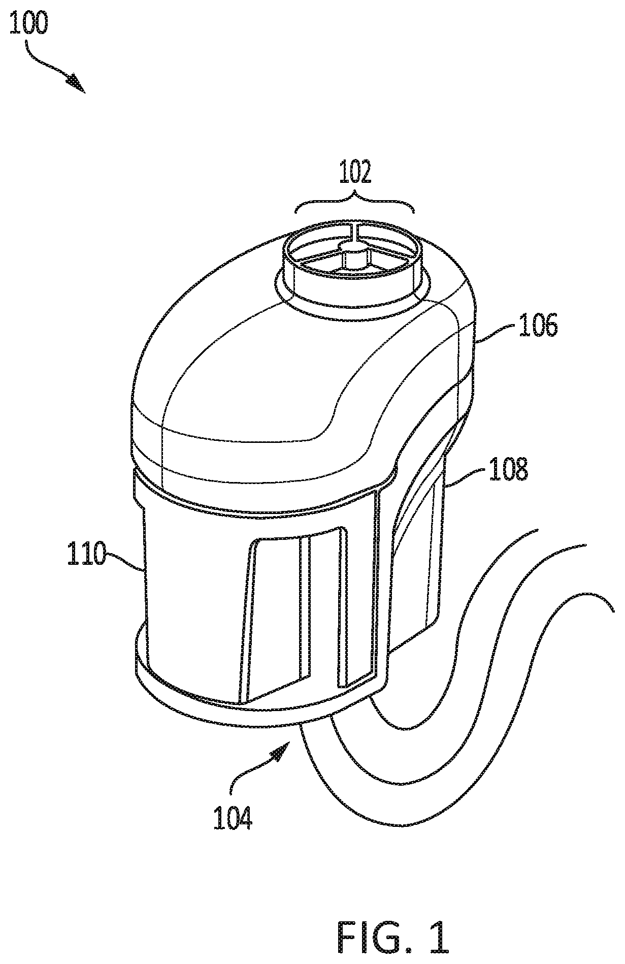
[0053] FIG. 1 shows a garbage separator system in accordance with some embodiments.
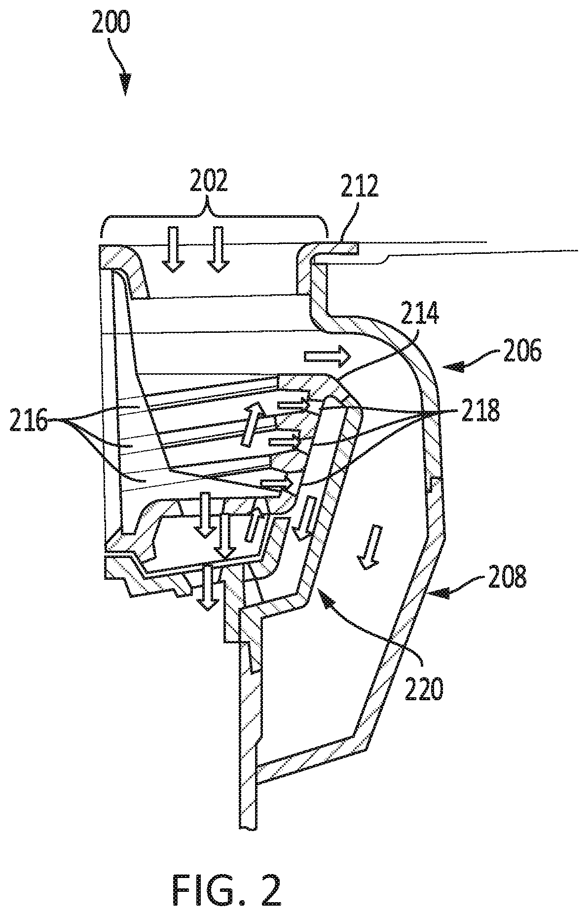
[0054] FIG. 2 shows a cross-sectional view of a garbage separator system in accordance with some embodiments.
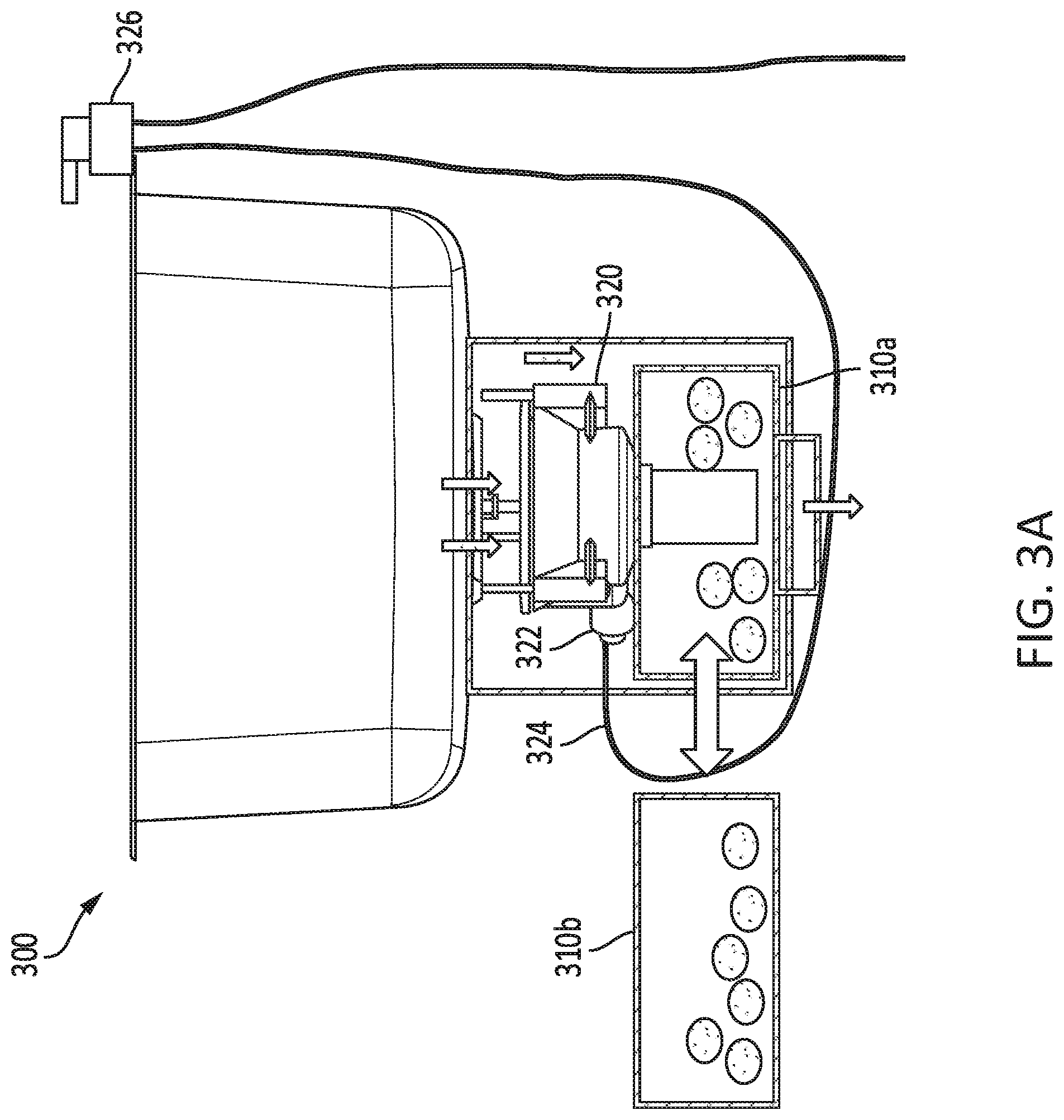
[0055] FIG. 3A shows a garbage separator system in accordance with some embodiments.
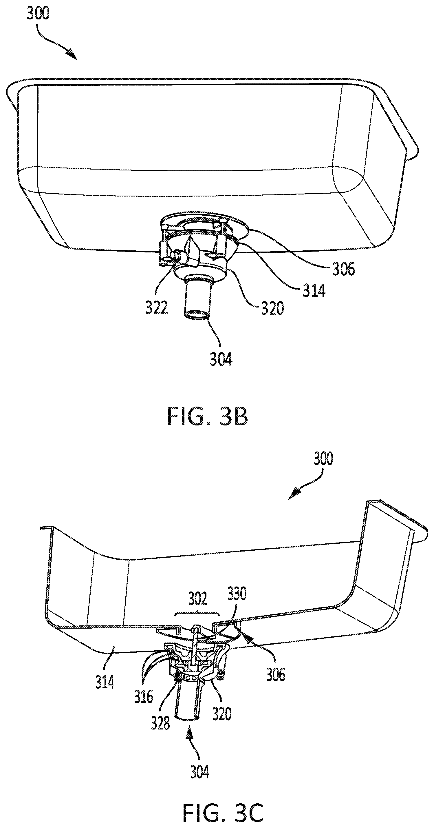
[0056] FIG. 3B shows a garbage separator system in accordance with some embodiments.
[0057] FIG. 3C shows a cross-sectional view of garbage separator system in accordance with some embodiments.
[0058] FIG. 3D shows a cross-sectional view of a garbage separator system in accordance with some embodiments.
[0059] FIG. 3E shows a garbage separator system in accordance with some embodiments.
[0060] FIG. 3F shows a garbage separator system in accordance with some embodiments.
[0061] FIG. 3G shows a cross-sectional view of a garbage separator system in accordance with some embodiments.
[0062] FIG. 3H shows a cross-sectional view of a garbage separator system in accordance with some embodiments.
[0063] FIG. 3I shows a garbage separator system in accordance with some embodiments.
[0064] FIG. 3J shows a cross-sectional view of a garbage separator system in accordance with some embodiments.
[0065] FIG. 3K shows a detail view of a garbage separator system in accordance with some embodiments.
[0066] FIG. 4A shows a garbage separator system in accordance with some embodiments.
[0067] FIG. 4B shows a garbage separator system in accordance with some embodiments.
[0068] FIG. 4C shows a garbage separator system in accordance with some embodiments.
[0069] FIG. 4D shows a garbage separator system in accordance with some embodiments.
[0070] FIG. 4E shows a cross-sectional view of a garbage separator system in accordance with some embodiments.
[0071] FIG. 4F shows a cross-sectional view of a garbage separator system in accordance with some embodiments
[0072] FIG. 5 shows a garbage separator system, in accordance with some embodiments.
[0073] FIG. 6 shows a garbage separator system, in accordance with some embodiments.
[0074] FIG. 7 shows a cutaway view of garbage separator system, in accordance with some embodiments.
[0075] FIG. 8 shows a garbage separator system, in accordance with some embodiments.
DETAILED DESCRIPTION OF THE INVENTION
[0076] As explained above, there is a need for improved systems, methods, and techniques for processing food waste that is poured into sinks. Accordingly, provided herein are garbage separator systems that may address that need.
[0077] A garbage separator system may be integrated into the drain of a sink to automatically separate food waste from the flow of drainage water. A rotating separator cup driven by a water turbine powered by water taken from the plumbing system of the integrated sink may use a plurality of helical blades to lift and push food particles upward and outward and into a waste bin, while drainage holes in the separator cup may allow drainage water to pass through the cup and into the plumbing drainage system. Alternately or additionally, a screw conveyor comprising a rotating helical blade may push food particles sideways and/or upward toward and into a waste bin, while drainage holes in the bottom and/or sides of a tube encasing the helical blade may allow drainage water to pass through the tube and into the plumbing drainage system. The waste bin may then be periodically manually emptied by a user. Examples or various embodiments of garbage separator systems are discussed below.
[0078] FIG. 1 shows a garbage separator system in accordance with some embodiments. As shown in FIG. 1, garbage separator system 100 may include upper shroud 106 and lower shroud 108 that may together form a housing for the main body of the garbage separator system. Upper shroud 106 may define or may be attached to an intake opening 102 formed on a top surface of the garbage separator system 100 that is configured to open to the drain of a sink when the system is installed below the drain of a sink. As shown, opening 102 may have one or more bars, guards, or obstructions covering the opening; these guards may be configured to prevent particles above a certain size from passing through the opening. For example, particles larger than one or more openings or passageways defined by the internal components of system 100 may be prevented from passing through opening 102. Lower shroud 108 may define or may be attached to an water outlet opening 104 that connects to a pipe through which drainage water may flow to a septic or sewer system. In some embodiments, a check-valve downstream of opening 104 may be included in order to prevent water from backing up into the system due to a clog. In the example of FIG. 1A, the drainage pipe connected to the bottom of garbage separator system 100 includes a trap formed by the bend in the pipe.
[0079] When system 100 is installed between a drain of a sink and the pipe leading to the septic or sewer system, the system may be configured to separate drainage water from food waste and other waste particles by directing food particles and other waste particles into removable waste bin 110, which may be any bucket, bin, basin, or receptacle that may he configured to collect waste particles and to be removed from the system, emptied, washed, and replaced. In the embodiment of FIG. 1, removable waste bin 110 may be slid away from lower shroud 108 to be temporarily removed from system 100. Unlike waste food particles directed to removable waste bin 110, drainage water may be allowed to pass through system 100 and out of the drainage pipe and into the septic or sewer system. Manners in which this separation may be achieved are discussed in further detail below with reference to the other figures and exemplary embodiments of this application.
[0080] FIG. 2 shows a cross-sectional view of a garbage separator system in accordance with some embodiments. Garbage separator system 200 has upper shroud 206 and lower shroud 208, which may share any or all characteristics with the respective shrouds 106 and 108 described above with reference to FIG. 1. Upper shroud 206 forms intake opening 202, which is an opening in the top of system 200 and is configured to be aligned underneath the drain of a sink to receive drainage water and waste particles to be processed and separated by the system. As shown in the example of FIG. 2, intake opening 202 is aligned with sink drain 212 such that water and/or waste food particles may be washed down sink drain 212 and fall into intake opening 202 for processing by system 200.
[0081] After water and/or waste food particles enter system 200 through intake opening 202, the water and/or particles may fall into a separator cup disposed below the opening. The separator cup may be any cup-shaped or bowl-shaped or generally concave-shaped receptacle configured to sit below an intake opening of a garbage separator system and to operate to separate water and waste particles. Namely, a separator cup may be configured to separate water from waste particles by allowing water to pass through one or more drainage holes or water openings in the separator cup; these holes may be configured to be large and numerous enough (e.g., they may account for a sufficiently large percentage of the surface area of the separator cup) to allow all water directed into the separator cup to pass through the separator and into the septic or sewer system.
[0082] Food and waste particles too large to pass through the drainage holes in the separator cup, however, may be caught by the cup as the water passes through, and may be lifted and moved upwards and outwards by helical blades disposed on the inner/upper surface of the separator cup. That is, the separator cup may be configured to rotate about an axis which may be aligned or substantially aligned with (or may be parallel or substantially parallel to and offset from the center a central axis of the drain of the sink under which the separator system is installed. The separator cup may be driven by an electric motor, a water turbine, or any other means that may cause it to rotate about its axis. As the separator cup rotates, the helical blades of the separator cup may push/lift food and waste particles up the inside walls of the separator cup, ultimately lifting the food and waste particles upward and outward over the top edge of the separator cup, where they may fall downward into a removable waste bin or other receptacle for food and waste particles.
[0083] In the example of FIG. 2, separator cup 214 is disposed below intake opening 202 and is configured to rotate along an axis aligned with the center of intake opening 202. Drainage holes 218 allow water to pass through separator cup 214 and continue to flow downward under the force of gravity. Separator cup 214 is nested inside cup basin 220, which may be any funnel-shaped receptacle, basin, cup, and/or piping segment configured to hold separator cup 214 and to direct the flow of drainage water that passes through separator cup 214 toward the opening at the bottom of system 200 that leads the drainage water to the plumbing system. For example, cup basin 220 may be a funnel-shaped portion that mates with the top of a pipe and opens upward, and that further mates with separator cup 214 such that separator cup 214 may sit inside the funnel portion of cup basin 220 and may rotate about its axis while inside cup basin 220. Cup basin 220 may thus catch water that passes through the sides of separator cup 214 and direct the water downward and toward a drainage pipe, while cup basin 220 may further serve to separate the water flow path inside system 200 from the rest of the space inside the housing of system 200 (e.g., inside upper shroud 206 and lower shroud 208). A chamber for the passage of waste/food particles ejected by separator cup 214 may be formed by the interior walls of upper shroud 206 and lower shroud 208 and by the exterior walls of cup basin 220 and any piping attached thereto, such that food/waste particles ejected by separator cup 214 may fall downward through the chamber and into a removable waste bin without being able to re-enter the flow path of the drainage water and therefore without being able to fall or flow into the septic or sewer system. As shown in FIG. 2, the space between separator cup 214 and cup basin 220 may be small enough such that food particles and/or water may not effectively fall or pass through any such opening.
[0084] FIGS. 3A-3K show various views of garbage separator system 300, which may share some or all characteristics in common with other garbage separator systems discussed herein, including garbage separator systems 100 and/or 200 and their corresponding components as discussed above with reference to FIGS. 1 and 2.
[0085] FIG. 3A shows a garbage separator system in accordance with some embodiments. Garbage separator system 300 may include an upper shroud and a lower shroud, which are shown in FIG. 3A as a continuous housing body. System 300 may include removable waste bin 310, which is shown in an inserted position 310a and a removed position 310b. System 300 may include separator cup 314 nested in cup basin 320. As shown in the illustration of FIG. 3A, system 300 may be configured to allow water to pass through separator cup 314 and cup basin 320 and into a drainage pipe and out of system 300, while food/waste particles (as shown by the circles in the illustration), may be ejected from separator cup 314 and caused to fall down inside the housing of system 300 and into removable waste bin 310 for later disposal, such as periodic manual disposal by a user.
[0086] As shown in FIG. 3A, system 300 may include water turbine water inlet 322, which may be an inlet for water that is in fluid connection with a water turbine chamber of a water turbine that drives rotation of separator cup 314. Inlet 322 may further be in fluid connection with water turbine water line 324, which may pass water from a main water line of the plumbing system associated with the sink toward and into inlet 322. The flow of water through water line 324 and into water inlet 322 may in some embodiments be controlled by a valve such as water turbine control valve 326, which may be any manually or electrically controllable valve that may allow or disallow the full and/or partial flow of water to a water turbine of system 300. By opening and/or closing valve 326, a user may therefore control whether water flows to the water turbine of the system and may therefore control whether separator cup 314 is caused to rotate (or control how fast separator cup 314 rotates). This may allow a user to functionally turn system 300 on and off, such that water may be run down the drain and through system 300 without separator cup 314 rotating when the system is off (such as when no food or waste particles are being passed down the drain). In some embodiments, inlet 322 may include one or more attachment mechanisms or attachment means for attaching inlet 322 to any associated pipe or water line. The attachment means or attachment mechanisms may include, for example, crimps or threading; in some embodiments, inlet 322 may include threading in accordance with American National Pipe Thread Standards, such as 1/4'' NPT threading, 3/8'' NPT threading, or 1/2'' NPT threading.
[0087] In some embodiments, one or more check valves may be used to prevent water and contaminants from flowing backward from the turbine chamber toward and/or into turbine water line 324.
[0088] In some embodiments, turbine control valve 326 may be replaced by or may work in conjunction with a pressure-assist valve, such as the one described below in greater detail with reference to FIG. 11.
[0089] FIG. 3B shows garbage separator system 300 in accordance with some embodiments. As shown in FIG. 3B, garbage separator system may include upper shroud 306, which may have a portion of its upper surface that is configured to be placed adjacent to the underside of the sink. In some embodiments, the upper portion of upper shroud 306 may be flat or substantially flat; in some other embodiments, the upper portion may have any shape that contours to the shape of the underside of the sink. In some embodiments, upper shroud 306 may be attached to the underside of the sink by any suitable mounting hardware, such as screws or bolts or the like, or such as any mounting system suitable for mounting a garbage disposal system to the underside of a sink. In some embodiments, upper shroud 306 may additionally or alternately be attached to cup basin 320, such as by any suitable mounting hardware such as screws, bolts, or the like. The connection between upper shroud 306 and cup basin 320 may create a vertical space between the two such that food and waste particles ejected from separator cup 314 may have enough room to pass up and over the edges of separator cup 314 and cup basin 320 while passing below the underside of upper shroud 306.
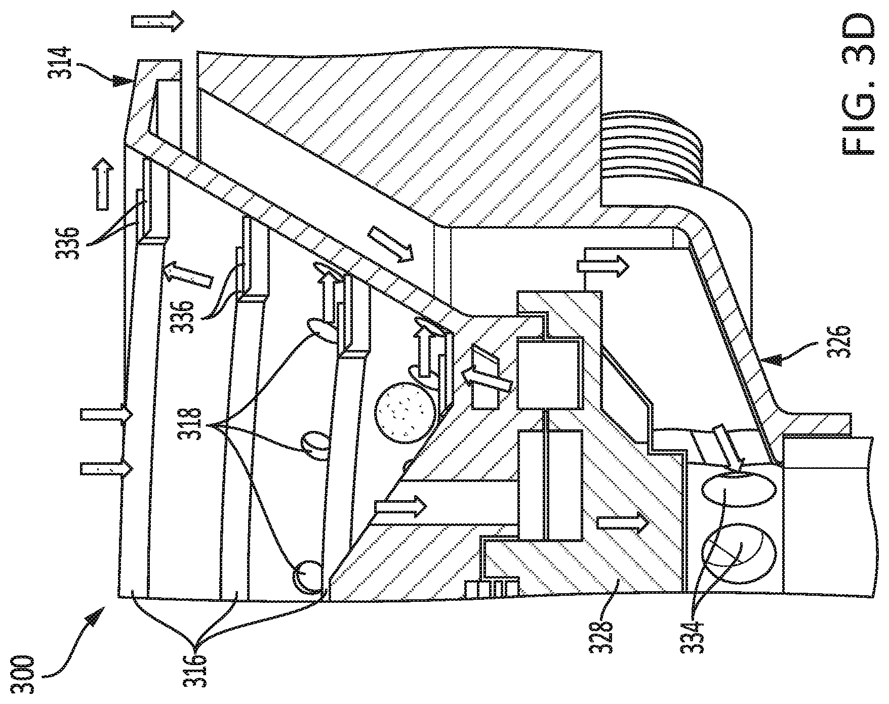
[0090] FIGS. 3C and 3D show cross-sectional views of garbage separator system 300 in accordance with some embodiments. FIG, 3C shows a view of garbage separator system 300 in attachment with a sink, as depicted in FIG. 3B, while FIG. 3D shows a detail cross-sectional view of certain internal components of system 300. As shown in FIG. 3D, separator cup 314 may have a convex portion 332 that is located at the bottom of the cup and is configured to cause food and waste particles to fall down the sides of the convex part toward the helical blades 316 at the wall of separator cup 314. Thus, rather than having a flat or concave floor, separator cup 314 may have a dome-shaped or cone-shaped floor that prevents waste particles from sitting in the middle of the floor of the cup; by nature of the floor of cup 314 slanting outward towards the walls of the cup, gravity and centrifugal force may combine to cause the waste particles to move toward helical blades 316 at the edge of cup 314.
[0091] FIG. 3D further depicts how helical blades 316 of separator cup 314 may have one or more helical blade ribs 336. Ribs 336 may be small protrusions located on helical blades 316 that may create additional friction driving food and waste particles sitting on top of the helical blades. In some embodiments, ribs 336 may be regularly spaced on helical blades 316. In some embodiments, ribs 336 may be located on top of, on the edge of, and/or on the bottom of helical blades 316. In some embodiments, ribs 336 may have a triangular cross-sectional shape, a rounded cross-sectional shape, a square cross-sectional shape, or any other suitable cross-sectional shape. In some embodiments, ribs 336 may form a straight line that may be radial to separator cup 314, may be angled from an axial orientation to separator cup 316, or may form a curved shape. In some embodiments, in place of or in addition to raised ribs 336, helical blades 316 may have one or more ridges or indentations in one or more surfaces of the blades configured to increase friction exerted on food/waste particles.
[0092] FIG. 3D further depicts how helical blades 316 may, in some embodiments, have a raised lip around an interior edge of one or more of the blades. The raised lip may have any suitable cross-sectional shape and may serve to prevent food/waste particles from sliding off of the helical blades, allowing the helical blades to exert greater outward force on food/waste particles. Furthermore, separator cup 314 may have a downwardly extending lip that protrudes downward from its outer rim; this lip may help prevent food/waste particles from entering the space above separator cup 314 and cup basin 320.
[0093] As shown in FIG. 3D, drainage holes 318 in separator cup 314 may be located at any suitable location on separator cup 314, including on the side walls near, through, or between helical blades 316. Drainage holes 318 may alternately or additionally be located on the floor of separator cup 314. In this way, water may drain out of the sides of separator cup 314 and run down the inside surface of funnel-shaped cup basin 320, or may alternately drain directly down through the floor of separator cup 314 and may fall directly into a drainage pipe without being further directed or diverted by cup basin 320.
[0094] As shown in FIG. 3D, cup basin 320 may itself contain one or more cup basin drainage holes 334. In the example shown, cup basin drainage holes 334 are formed through a portion of cup basin 320 that connects a lower portion of cup basin 320 and a drainage pipe of system 300 to an upper portion of cup basin 320 and an element that sits atop cup basin 320. In the example shown, water turbine chamber lower part 328 sits atop cup basin 320, while in some other embodiments separator cup 314 may sit directly atop cup basin 320. In the example shown, the portion of cup basin 320 at which holes 334 are located forms a circular pipe-like structure that connects a drainage pipe below to the opening of various drainage holes 318 formed in the bottom of separator cup 314 above. Drainage holes 334 may allow water to run from the funnel portion of cup basin 320 into a center portion of cup basin 320 and to fall down into the drainage pipe below, while still allowing cup basin 320 to support elements of system 300 that sit atop cup basin 320, such as water turbine chamber parts or a separator cup or elements attached thereto.
[0095] FIG. 3D also depicts water turbine chamber lower part 328, which may be a component of system 300 that forms all or part of a chamber for housing a water turbine. In some embodiments, as discussed above, a water turbine may be used to drive rotation of a separator cup under the force of water provided from the water supply associated with the sink. Blades of the water turbine may be located inside a chamber (e.g., a ring- or torus-shaped chamber) and may be formed as part of the separator cup or configured to engage the separator cup, such that driving the blades under force of flowing water may cause the separator cup to rotate. In the embodiment shown, the chamber has a square ring shape (e.g., a square cross-sectional shape that rotates in a ring around the center axis of rotation of the water turbine and the separator cup) and is defined on its upper half by a channel in the underside of separator cup 314 and on its lower half by a channel formed in water turbine chamber lower part 328.
[0096] In some embodiments, water turbine chamber lower part 328 may be ring-shaped or collar-shaped such that it may define a vertical channel or tube through the middle, through which water may pass after draining from separator cup 314 and before calling downward toward a drainage pipe. As shown in FIG. 3D, water turbine chamber lower part 328 may be configured to sit atop and engage cup basin 320 and to sit below and engage separator cup 314. Separator cup 314 may rotate while sitting atop water turbine chamber lower part 328, while water turbine chamber lower part 328 may in some embodiments not rotate.
[0097] The chamber formed in part by water turbine chamber lower part 328 may be in fluid connection with water turbine water inlet 322, such that water flowing into water turbine water inlet 322 may then flow to the water turbine chamber defined in part by water turbine chamber lower part 328. A fully enclosed channel or tube in fluid connection with water turbine water inlet 322 may, for example, open to the ring-shaped partial-channel or half-channel configured to contain the water turbine blades. Water turbine chamber lower part 328 may, in some embodiments, have one or more drainage holes through which water may drain after driving the turbine blades.
[0098] FIGS. 3E and 3F show different views of garbage separator system 300 in accordance with some embodiments. As shown in FIGS. 3E and 3F, water turbine chamber lower part 328 may include a tubular portion that extends from the chamber portion (ring portion) outward towards the edge of the system 300 in order to join in fluid connection with water turbine water inlet 322. In order to provide efficient water pressure to the water turbine, the tubular portion of water turbine chamber lower part 328 may be aligned in a straight line with the opening of water turbine water inlet 322 and may align tangentially to the circular turbine chamber formed in part by the chamber portion of water turbine chamber lower part 328, such that water may flow into water turbine chamber inlet 322 and may enter the turbine chamber without being directed around a curve or a corner. As shown in FIG. 3F, the tubular portion of water turbine chamber lower part 328 may be positioned slightly below the turbine chamber such that the tubular portion may curve or bend slightly upward in order for the water flowing through the tubular portion to reach the turbine chamber.
[0099] FIGS. 3G and 3H show cross-sectional views of garbage separator system 300 in accordance with some embodiments. FIGS. 3G and 3H illustrate the hollow center of the tubular portion of water turbine chamber lower part 328 which may carry water from water turbine water inlet 322 to the turbine chamber. In the illustrated embodiment, the tubular portion of water turbine chamber lower part 328 has a circular channel for the flow of water, while the turbine chamber is rectangular.
[0100] As shown in FIG. 3G, separator cup 314 may be configured to rotate about spindle 330, which may be any rod or axis. Spindle 330 may in some embodiments be formed of a metal resistant to rusting and wear, such as stainless steel. In some embodiments, spindle 330 may be mounted at its bottom end in a cavity of water turbine chamber lower part 328, may pass through a center portion of separator cup 314, and may be mounted at its top end in a cavity of upper shroud 306, such as a cavity formed on the underside of a bar or guard centered on opening 302, thereby allowing separator cup 314 to rotate about an axis aligned with the center of opening 302.
[0101] As further shown in FIG. 3G, system 300 may comprise thrust washer 340, or any other suitable type of rotary bearing. In some embodiments, thrust washer 340 may be disposed around spindle 330 and configured to support the weight of separator cup 314 as it sits atop thrust washer 340. In some embodiments, any other suitable bearing or mechanism configured to allow rotation of the separator cup and/or to support some or all of the weight of the separator cup may be used in addition to or in place of thrust washer 340.
[0102] As shown in FIG. 3H, water turbine chamber lower part 328 may include a central portion which may mate or couple with spindle 330, a series of spoke portions that extend radially outward from the central portion, a chamber portion that forms the housing for the lower portion of the turbine chamber, and a tubular portion that extends tangentially from the chamber portion to water turbine water inlet 322. Connecting the central portion to the chamber portion that surrounds it via one or more spokes, rather than by a large or continuous connection, may create one or more open spaces between the chamber portion and the central portion through which drain water may fall from separator cup 314 down toward a drainage pipe.
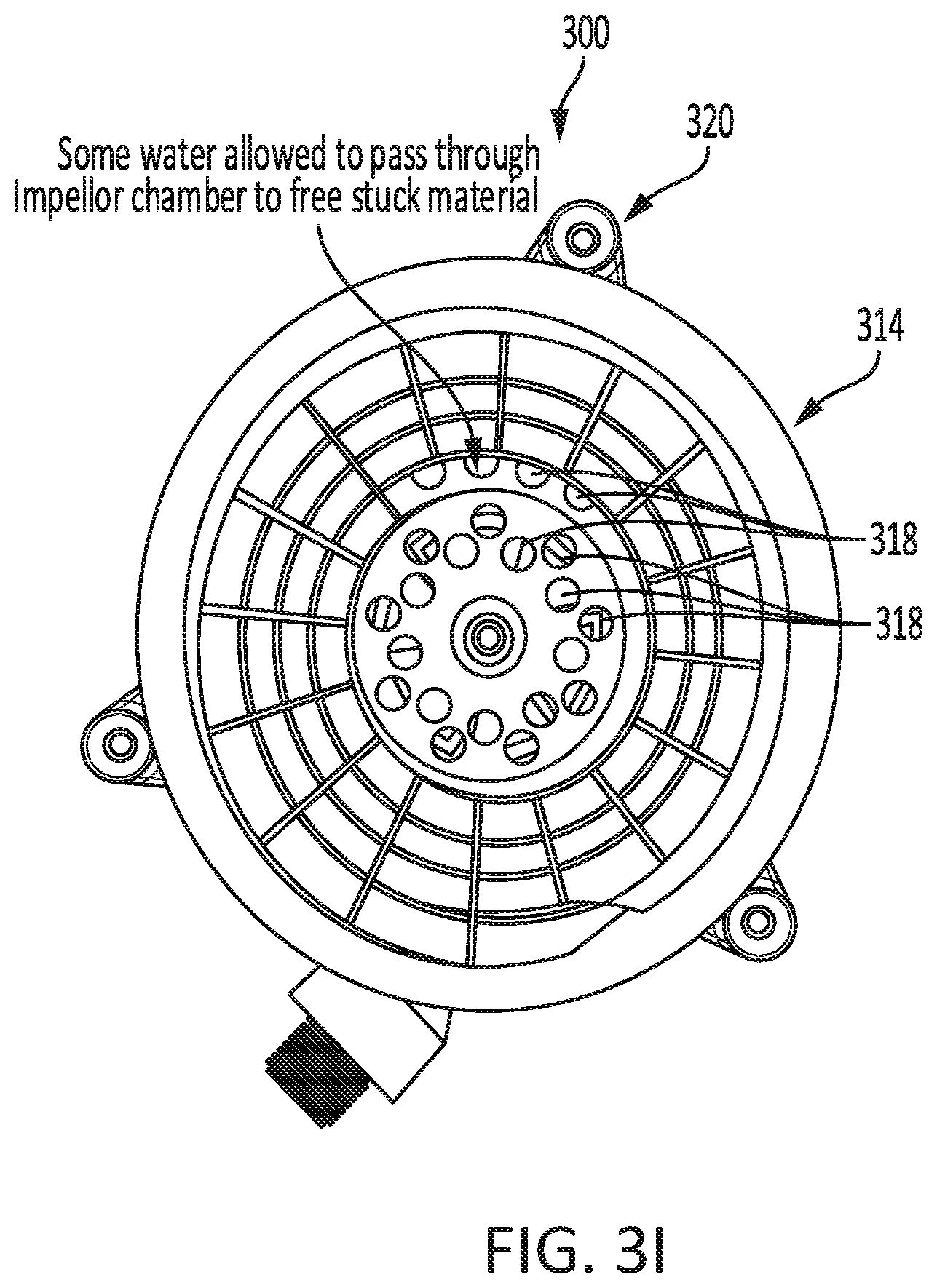
[0103] FIG. 3I shows a garbage separator system in accordance with some embodiments. FIG. 3I illustrates how separator cup 314 may have one or more drainage holes 318 that are positioned on the separator cup 314 such that they may open into the turbine chamber. In some embodiments, the top of the turbine chamber may be open at some or all portions such that water may flow between the turbine chamber and separator cup 314. In some embodiments, water passing through these holes may allow for food/waste particles that are stuck to become unstuck.
[0104] FIGS. 3J and 3K show an example of a garbage separator system. The garbage separator system and subcomponents thereof shown in these figures may share some or all properties with systems 100, 200, and/or 300 (and their subcomponents) as discussed above.
[0105] In the embodiment of FIGS. 3J and 3K, separator cup 314 may have helical blades 316 having a pitch (e.g., vertical offset) of 14 mm, and a width of 8 mm. Helical blades 316 may protrude from the wall of separator cup 314 and create an underhang underneath the blades. Drainage holes 318 may be circular in shape and are spaced apart horizontally by a distance greater than the width of the holes themselves, and may account for less than 50%, less than 25%, or less than 10% of the surface area of separator cup 314.
[0106] In other embodiments, garbage separator systems may have separator cups having one or more properties that are different from the separator cup of the system shown in FIGS. 3J and 3K. The separator cups discussed in the embodiments below may be integrated into garbage separator systems that may share some or all properties with systems 100, 200, and/or 300 (and their subcomponents) as discussed above.
[0107] In some embodiments, a separator cup may have helical blades having a pitch (e.g., vertical offset) of 18 mm, and a width of 5 mm. The overall shape (e.g., the wall angle, width, height, etc,) of the separator cup may be similar to the shape of separator cup 314. The helical blades may be wedge-shaped, such that they do not create any underhang space beneath them. In some embodiments, elimination of an underhang space may prevent food/waste particles from becoming trapped beneath the blades and may reduce buildup of grime on the separator cup. Drainage holes may be rectangular in shape and may be spaced apart horizontally by a distance approximately equal to the width of the holes themselves. Drainage holes may account for more than 10%, more than 25%, or more than 50% of the surface area of the separator cup.
[0108] In some embodiments, a separator cup may have helical blades having a pitch (e.g., vertical offset) of 18 mm, and a width of 3 mm. The overall shape (e.g., the wall angle, width, height, etc.) of such a separator cup and the arrangement and shape of drainage holes in such a separator cup may be similar to the shape and drainage hole arrangement of other separator cups discussed herein.
[0109] In some embodiments, a separator cup may have no helical blades. In garbage separator systems having no helical blades, the outward forces exerted on waste/food particles by the sloped floor of the separator cup and by the rotation (e.g., centrifugal forces exerted on the waste food particles) of the separator cup may be the only forces acting to expel waste/food particles upwards and outwards and to eject them from the separator cup. The overall shape (e.g., the wall angle, width, height, etc.) of a separator cup having no helical blades and the arrangement and shape of drainage holes in such a separator cup may be similar to the shape and drainage hole arrangement of other separator cups discussed herein.
[0110] In some embodiments, a garbage separator system may include an intake opening, a water outlet, an upper shroud, a lower shroud, a removable waste bin, a separator cup, helical blades, separator cup drainage holes, a cup basin, a water turbine water inlet, a spindle, separator cup convex portion, cup basin drainage holes, and a thrust washer. Such a garbage separator system and its components may share some or all characteristics in common with other garbage separator systems discussed herein, including garbage separator systems 100, 200, and/or 300 and their corresponding components as discussed above with reference to FIGS. 1-3; in some embodiments, such a garbage separator system may differ from other garbage separator systems discussed herein, including garbage separator systems 100, 200, and/or 300, in that the turbine of systems 100, 200, and/or 300 may be molded into the separator cup, whereas the turbine of such a garbage separator system may be a separate part in a separate chamber. In some embodiments, an integral turbine molded into the separator cup may be more economical in that it requires fewer separate parts, but it may in some embodiments be more difficult to seal.
[0111] A separator cup of such a garbage separator system may have a lesser height, a shallower side-wall angle, and/or a shallower convex portion as compared to separator cup 314 and its convex portion 332. In further differentiation from the embodiment of garbage separator 300, a spindle may only extend to the top of a separator cup convex portion, rather than extending through the space above the floor of the separator cup and up toward the upper shroud, inlet opening, and sink drain as in system 300. In some embodiments, a spindle not extending above the floor of a separator cup may make it less likely that food or waste particles become clogged in the system by colliding with the spindle.
[0112] In some such embodiments, a separator cup sits atop a water turbine chamber. Whereas in the embodiment of system 300 described above with reference to FIG. 3, separator cup 314 sits directly atop water turbine chamber lower part 328 (which joins directly to water turbine water inlet 322), some embodiments include a distinct element between a water turbine water inlet and a separator cup. In some embodiments, the blades of the water turbine may be located in a turbine chamber separated from (rather than defined in part by) the body of the separator cup; thus, rather than the turbine blades being attached directly to separator cup 314 as in system 300, the turbine blades of some such systems may be separate from a separator cup and may be contained within a turbine chamber that is separate from the separator cup. The turbine blades may drive an axis (e.g., a spindle) or another component that is attached to or engages with the separator cup to cause rotation of the separator cup. Having the separator cup being distinct from the water turbine chamber may help, in some embodiments, to prevent the leakage of water from water turbine chamber.
[0113] In some such embodiments, a lower shroud may guide food/waste particles into a removable waste bin. A lower shroud may have a slanted wall portion that slants inward. toward the center of the garbage separator system to form a downward slope toward the opposite side of the system. This downward inward slope may allow food/waste particles to fall down the slope and be guided toward the side of the system in which the removable waste bin is located. The removable waste bin may be configured to be inserted and removed from the lower shroud, such that the bin may slide in and out of a cavity in the lower shroud. The lower shroud may be internally open to the removable waste bin such that food/waste particles ejected over the top rim of a separator cup and cup basin tray fall downward inside the upper shroud and lower shroud and fall into the open top side of the removable waste bin\. The removable waste bin and lower shroud may have side walls that are shaped to form an easily grippable portion for easy manual removal of bin by a user. For example, two indentations may form a handhold by which the user can grab the bin to slide it out. The side walls of the bin and lower shroud may align with one another such that food/waste does not escape when falling and such that odors do not escape the waste bin.
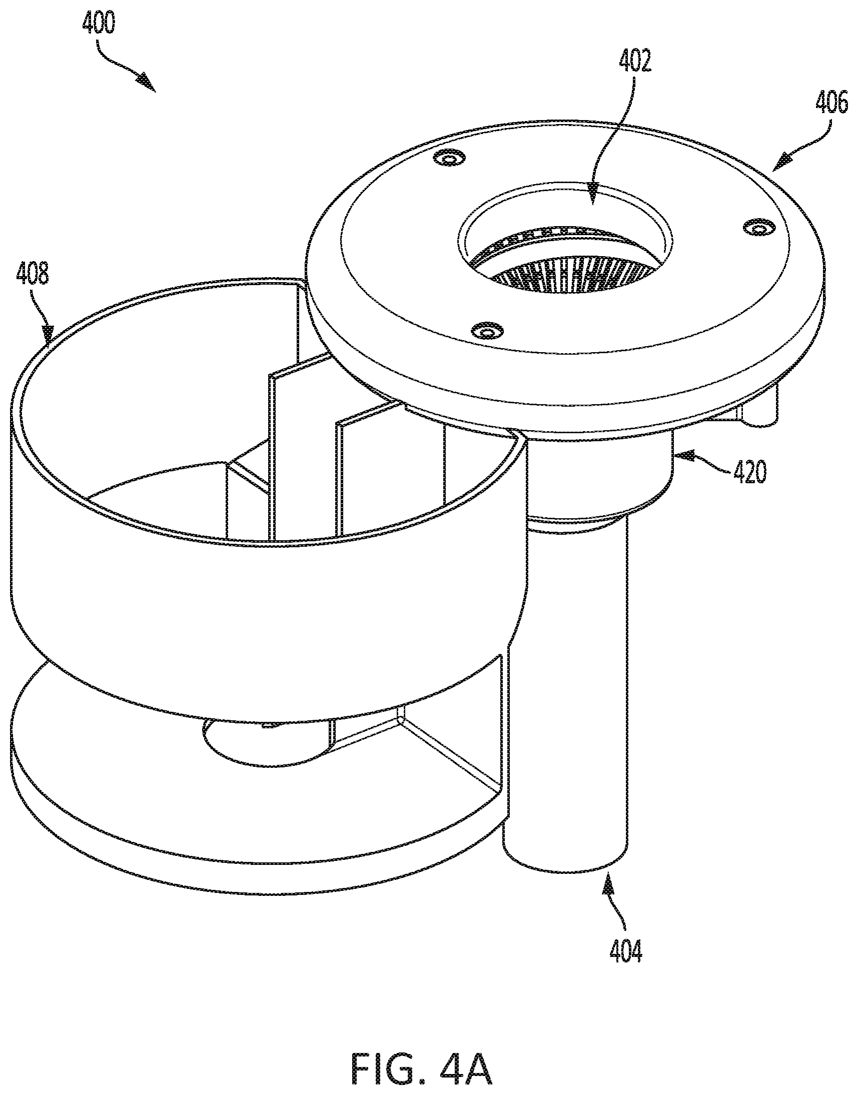
[0114] FIGS. 4A-4F show various views of garbage separator system 400, which may include intake opening 402, water outlet 404, upper shroud 406, lower shroud 408, removable waste bin 410, separator cup 414, helical blades 416, separator cup drainage holes 418, cup basin 420, water turbine water inlet 422, spindle 430, separator cup convex portion 432, and cup basin drainage holes 434. Garbage separator system 400 and its components may share some or all characteristics in common with other garbage separator systems discussed herein, including garbage separator systems 100, 200, and/or 300 and their corresponding components as discussed above with reference to FIGS. 1-3.
[0115] FIGS. 4A and 4B depict views of garbage separator system 400 that demonstrate how lower shroud 408 may in some embodiments be removable from and/or able to be fully or partly disengaged from one or more other components of the system 400. In some embodiments, separation or disengagement of the lower shroud may allow for it to be periodically cleaned by a user. In the embodiment shown in FIGS. 4A and 4B, lower shroud 408 may slide horizontally away from system 400 to be removed; lower shroud 408 may be shaped such that a notch (e.g., a cut-out) extends from one side of shroud 408 to the center of shroud 408, such that shroud 408 may slide around centrally located components of system 400 such as cup basin 420 and a vertical drainage pipe of system 400. When shroud 408 is engaged with system 400, a central drainage column of system 400 may sit at the centermost portion of the notch formed in shroud 408. In some embodiments, system 400 (or other garbage separator systems herein) may be configured such that a separator cup, return manifold and impeller motor may all slide out for removal for cleaning together, and such that the various components may be able to be separated from one another for cleaning once they have been slid out from the system.
[0116] In some embodiments, including those with removable components, connections between fluid-carrying components may be made with gaskets, press-in tube, o-rings, and/or retaining latches; this may prevent operating pressure of the system from pushing connections apart from one another, in some embodiments (such as electrically-powered embodiments of the system), connections between components may be made using receptacles similar to those in rechargeable batteries for power tools.
[0117] In some embodiments in which shroud 408 includes a slot or notch allowing it to be slid off of system 400 around central components of system 400 such as cup basin 420, cup basin 420 may form a partial seal against the outer rim of upper shroud 406. For example, cup basin 420 may join or touch upper shroud 406 for a portion of the circumference of cup basin 420 and/or upper shroud 406 such that food particles ejected from separator cup 414 may not fall over the edge of separator cup 414 and down through the open notch/slot of lower shroud 408 and out of system 400 entirely. Thus, the portion of cup basin 420 that approaches, joins with, or touches upper shroud 406 may align with the notch/slot in lower shroud 408 in order to prevent food/waste particles from being ejected in the direction of the notch/slot.
[0118] FIGS. 4C and 4D show how, in some embodiments, garbage separator system 400 may include cleaning agent supply 442. In some embodiments, cleaning agent supply 442 may be a supply of any soap, detergent, chemical, solution, or cleaner configured to be used to clean a garbage separator, sink, or any associated component. In some embodiments, cleaning agent supply 442 may comprise a bottle, bag, cartridge, or other container of liquid cleaning solution.
[0119] As shown in FIG. 4E, in some embodiments, separator cup 414 may be configured to catch and prevent water from being pushed over the top of the edge of the separator cup, such as by including one or more protrusions and/or indentations configured to interrupt the flow of water toward and/or over the edge of the separator cup.
[0120] In some embodiments, cleaning agent supply 442 may include a concentrated cleaning solution or cleaning fluid configured to be mixed with water provided from the water source of a sink system and to accordingly be diluted to an appropriate concentration for cleaning of the sink or of an associated garbage separator system. Using a concentrated cleaner may be advantageous because it may decrease the burden in refilling or otherwise repeatedly providing larger volumes of diluted cleaning solution. For example, a user of garbage separator system 400 may simply need to periodically replace a small, lightweight bottle, cartridge, bag, or other container of concentrated cleaner. Thus, concentrated cleaner configured to be automatically diluted from water provided by a sink system may substantially lower the physical burden on users cleaning garbage separator components and, further, may decrease the inconvenience of needing to perform frequent manual operations to apply cleaner directly or to refill or replace containers of dilute cleaner or water.
[0121] In some embodiments, cleaning agent supply 442 may comprise a bottle, bag, cartridge, or other container configured to be attached to one or more other components of garbage separator system 400. In some embodiments, a container of concentrated cleaning liquid may be configured to be inserted into an opening on a pipe or other component of a garbage separator system. For example, a container of cleaning liquid may have an opening, such as an opening at a top of a bottle or an opening joined to a bag, that is configured to be joined to an opening of a component of a garbage separator system. In some embodiments, the opening may have threads along an outer or inner edge such that the opening may be threaded onto and attached securely to the component. In some embodiments, other techniques may be used to attach the opening, including, but not limited to, mechanical attachment (clasps, buckles, snaps, clamps, etc.), suction, magnetic attachment, or any other suitable attachment device, system, or technique. In some embodiments, attachment systems and/or techniques may be configured to allow simple and repeated attachment, detachment, and re-attachment such that a user may replace or refill the container as necessary.
[0122] In some embodiments, the container may be a bottle or bag containing cleaner liquid. In some embodiments, the container may have a round opening having threads configured to attach to a threaded opening on a component of the separator system such that the container may be screwed onto the separator system to attach into place in fluid connection with the attached component. In some embodiments, the container may be configured to attach to garbage separator system 400 such that the opening faces downward and such that gravity may cause the liquid in the container to flow out of the container. In some embodiments, such as those in which the container is configured to attach such that the opening on the container is not facing downward, other techniques may be used to cause flow of liquid out of the container. For example, suction may be created to cause flow of liquid out of the container; in some embodiments, suction may applied via a pump powered by electrical power and/or by a Venturi pump system creating suction due to the flow of water through the pipes associated with the garbage separator system.
[0123] In some embodiments, the container of cleaning agent supply 442 may be partially or substantially inflexible, such as when the container is a bottle. In some such embodiments, an air outlet may be included in the container such that, as suction is applied to the container or as gravity operates to move liquid out of the container, the container may refill with air as the liquid exits. For example, a second opening may be provided in the container to allow air to enter the container; the second opening may be configured or positioned such that liquid may not flow out of it. In some embodiments, the second opening may be configured to be closed until the container is attached to the system, at which time the opening may be automatically opened, such as by being punctured or pressed into an open position by the force applied by the user in attaching the container (e.g., the second opening may be covered by foil or plastic that is punctured when the container is placed into the attached position). In some embodiments, the primary opening of the container (e.g., the opening configured to allow liquid to flow out of the container), may similarly (e.g., additionally or alternatively) be configured to be closed or sealed before attachment and to be automatically opened when the container is attached.
[0124] In some embodiments, rather than being configured to be able to fill with air as liquid exits the container, the container may be configured as a substantially flexible and collapsible bag such that the container may compress and/or collapse under the suction force applied to it so that it has substantially no volume when completely collapsed under the section force (e.g., less than 20%, less than 10%, less than 5%, less than 2%, or less than 1% of the volume when full). In these embodiments, there may be no need to allow the container to fill with air. In some such embodiments, the container may be a plastic bag, which may optionally be contained inside a substantially inflexible outer container (e.g., bottle or cartridge).
[0125] In some embodiments, in order to allow for liquid to be drawn from the container when the opening is positioned at the top of the container (e.g., when liquid is drawn from the container by suction rather than by gravity), a straw or other tube may be positioned inside the container in order to allow a suction force to be applied to the bottom of the container and to draw liquid upward from the bottom of the container, even when an upper portion of the container adjacent to the opening is filled only with air. In some embodiments, the straw may be an integrated part of the container itself, such as a straw attached to the underside of a cap of the container, configured such that the opening at the top of the straw may be punctured or otherwise opened when the container is attached to a component of garbage separator system 400. In some embodiments, the straw may be a part of the component of garbage separator system 400 to which the container attaches, such that the container opening slides around the straw as the container is attached to the component.
[0126] In some embodiments, such as those shown in FIGS. 4C-4F, cleaning agent supply 442 may be fluidly connected to water turbine water line 424 such that cleaning fluid or detergent may enter water turbine water line 424 and flow separator cup 414. In some embodiments, cleaning fluid or detergent may enter water turbine water line 424 and flow directly into the water turbine, such that the water turbine blades and the inside of the water turbine chamber may be cleaned.
[0127] In some embodiments, water turbine water line 424 may be fluidly connected to another water line, such as cup basin cleaning water line 448, that splits from water turbine water line 424 and directs water into the inside of cup basin 420. Cup basin cleaning water line 448 may, as shown in FIGS. 4C-4F, have a smaller diameter than water turbine water line 424. In some embodiments, cup basin cleaning water line 448 may direct a flow of water and cleaning fluid/detergent to the inside of cup basin 420 such that the inside of cup basin 420 may be automatically cleaned when system 400 is used.
[0128] In some embodiments, as shown in FIGS. 4C-4F, cup basin cleaning water line 448 may be attached to valve 450, which may in some embodiments be physically or electrically controllable to block or allow the flow of water and cleaning fluid from cup basin cleaning water line 448, such that a cup basin cleaning function of system 400 may in some embodiments be activated and/or deactivated separately from the water turbine driving the primary garbage separation function of system 400. In some embodiments, cup basin cleaning water line 448 may terminate at valve 450 at a tangential orientation to the edge of cup basin 420, such that water may be sprayed along the interior circular surface of cup basin 420. In some embodiments, water may be sprayed in the opposite direction of rotation of separator cup 414 in order to be most effective at cleaning off stuck debris on cup basin 420.
[0129] In the examples of FIGS. 4C-4F, cleaning agent supply 442 is shown as attaching to water turbine water line 424 upstream of the connection of water turbine water line 424 and cup basin cleaning water line 448; however, in some embodiments, cleaning agent supply 442 may attach directly to cup basin cleaning water line 448 downstream of the connection of water turbine water line 424 and cup basin cleaning water line 448, such that cleaning fluid/detergent may be directed solely into cup basin 420 and not into the turbine chamber.
[0130] In some embodiments, cleaning agent supply 442 may be fluidly connected to a pump that may cause cleaning agent to flow into the attached water lines. In some embodiments, such a pump may be powered by electrical power and may be configured to apply suction force to draw in liquid from cleaning agent supply 442 and to output the liquid toward and/or into the flow path. Upon being drawn into the flow of water, the liquid of cleaning agent supply 442 may be mixed into and diluted in the water flow. In some embodiments, alternately or in addition to the arrangement including a pump as described above, cleaning agent supply 442 may be fluidly connected to a Venturi, which may be downstream from cleaning agent supply 442. In some embodiments, a Venturi may be any valve configured to create suction due to the Venturi effect. In some embodiments, a Venturi may be positioned in the flow path such that a primary flow of water may flow through the Venturi along water turbine water line 448 and such that the flow of water may create a pressure difference that applies suction to an inlet that is fluidly connected to cleaning agent supply 442 such that cleaning agent is drawn into the primary flow of water by the suction force. Upon being drawn into the flow of water, the liquid of cleaning agent supply 442 may be mixed into and diluted in the water flow. In some embodiments, a Venturi may be controlled by and/or positioned adjacent to a solenoid such that current delivered to the solenoid may cause the inlet of the Venturi to be selectably opened and closed so that cleaner may flow to or be blocked from flowing to the inlet.
[0131] In some embodiments, a user may inject cleaning fluid into the system via one or more primer bulbs. For example, a user may create pressure and/or suction by pressing a primer bulb, and the pressure or suction may cause cleaning agent to flow toward and/or into the flow path terminating at the water turbine chamber and/or valve 450.
[0132] In some embodiments, a garbage separator system may be configured to be self-cleaning. For example, the garbage separator system may be configured to be able to perform a cleaning cycle without the need for a user to manually disassemble and/or manually clean one or more components of the system. In some embodiments, the system may be configured such that a cleaning cycle may be performed on a regular basis (e.g., a timer or calendar), may be performed in accordance with a user command, and/or may be performed in accordance with the system detecting one or more trigger conditions causing the system to determine that the cycle should be performed.
[0133] In some embodiments, a self-cleaning garbage separator system may be configured to automatically cause water and/or cleaning fluid to flow through and/or over one or more components the system in the absence of waste and or ink water flowing over or through the one or more components of the system. In some embodiments, performing a cleaning cycle may comprise dispensing more cleaning fluid than would be used during regular operation of the system, or cleaning fluid may only be dispensed during a cleaning cycle and not used at all during regular operation of the system. In some embodiments, one or more valves of the system may be controlled such that higher or lower water pressure may be used during a cleaning cycle as compared to during regular operation of the system.
[0134] In some embodiments, the system may include one or more covers that engages the system during a cleaning cycle. For example, a cover may be configured to cover the drain opening during a cleaning cycle such that water and/or cleaning solution does not flow out of the system during the cleaning cycle. In some embodiments, a cover may be configured to engage the system through mechanical attachment (e.g., latches, hooks, screws), magnetic attachment, suction attachment, or through any other suitable engagement or attachment mechanism or technique. Using a cover may prevent water, cleaning fluid, steam, and/or waste from being ejected from the system during a cleaning cycle, and may therefore improve safety and cleanliness during performance of a cleaning cycle.
[0135] In some embodiments, a garbage separator system may include an intake opening, a water outlet, an upper shroud, a lower shroud, a removable waste bin, a separator cup, a cup basin, a water turbine chamber, an attachment ring, and a fixed housing. In some embodiments, such a garbage separator system and its components may share some or all characteristics in common with other garbage separator systems discussed herein, including garbage separator systems 100, 200, 300, 400 and their corresponding components as discussed above with reference to FIGS. 1-4.
[0136] In some embodiments of such a garbage separator, the lower shroud, upper shroud, collection bin, and various other components of the system may be separable from one another, such as by being configured to be able to be fully or partly disengaged from one or more other components of the system. In some embodiments, separation or disengagement of various components may allow them to be cleaned by a user. In some embodiments, the lower shroud and bin may slide horizontally away from the system to be removed; the upper shroud may be upwardly removable from the fixed housing; and the separator cup, cup basin, and water turbine chamber may be upwardly removable (together and/or separately from one another) from the lower shroud.
[0137] In some embodiments, a garbage separator system may include an upper shroud, a removable waste bin, a fixed housing, a water turbine chamber, a water turbine water inlet, a water turbine water outlet, a water turbine water inlet connection, a water turbine water outlet connection, and a handle. In some embodiments, such a garbage separator system and its components may share some or all characteristics in common with other garbage separator systems discussed herein, including garbage separator systems 100, 200, 300, and/or 400 and their corresponding components as discussed above with reference to FIGS. 1-4.
[0138] In some embodiments, such a garbage separator system may have both a water turbine water inlet and a dedicated water turbine water outlet. That is, rather than all water that runs through the water turbine draining directly into the same drainage system into which food particles and drain water flows, some or all of the water from the water turbine chamber may instead be directed to flow out of a dedicated outlet. In some embodiments, the dedicated water turbine water outlet may direct the flow of water from the water turbine chamber to an air gap, which may prevent water from being forced back toward the inlet source in the event of a clog or blockage and which may be required for code compliance in some jurisdictions. In some embodiments, after flowing to and through an air gap, the water that has flowed through the water turbine may thereafter be directed toward and into the drain itself. In some embodiments, an air gap associated with the system may be mounted on top of a sink and/or countertop associated with the system.
[0139] For example, water may flow into the water turbine chamber through the water turbine water inlet, and may flow out of the water turbine chamber through the water turbine water outlet. The outlet may in some embodiments share any one or more characteristics in common with the inlet of the system (or other water turbine inlets described herein), except that it may be configured such that water flows out of it rather than into it. After flowing out of the outlet, the water may be directed to flow through an air gap and then into a drain.
[0140] Furthermore, such a garbage separator system may have a water turbine inlet and/or water turbine outlet that is removable from a connector, such that the water turbine chamber (along with the inlet and outlet) may be removed from a water source and/or a water outlet destination. For example, in systems in which one or more components may be removed from a fixed housing and/or separated from one another, a water turbine inlet may be detachable from a water turbine water inlet connection, and a water turbine outlet may be detachable from a water turbine water outlet connection. In some embodiments, an inlet connection and/or outlet connection may be a port or other connection configured to be fluidly connectable to a water turbine inlet and/or outlet. In some embodiments, an inlet connection and/or outlet connection may be smaller in diameter than its corresponding connecting component or alternately may be larger in diameter than its corresponding connecting components, such that one may slide into the other in order to be connected. In some embodiments, an inlet connection and/or outlet connection may be connectible by threads, o-rings, force seals, or any other suitable connection mechanism(s).
[0141] For example, the water turbine water inlet connection and the water turbine water outlet connection may be connectible to the inlet and the outlet, respectively, by o-ring seals. In this way, the water turbine chamber may be pulled away from a fixed housing such that the inlet and the outlet detach from the respective connections, and the chamber may then be forced back in the other direction such that the inlet and the outlet reattach to the connections. In some embodiments, o-ring connection mechanisms may allow for simple linear movements to be used for disconnection and reconnection, such that more than one connection may be disconnected and/or reconnected at once by a simple linear motion of the overall water turbine chamber, which may not be possible in certain embodiments if the connections rely on threaded connection mechanisms in which each connection must be rotated independently.
[0142] In some embodiments, attachment and detachment of inlet components and outlet components for the flow of water to and from a water turbine chamber may require one or more mechanisms to ensure that sufficient force is applied to hold one or more components in an attached position. For example, one or more components may need to be locked into place in order for the connections to hold under the force of water pressure being applied to them. In some embodiments, one or more components may be held in place by latches, hooks, cams, handled, or some combination thereof. In some embodiments, locking one or more components into place with one or more cams may be advantageous because it may enable the application of sufficient linear pressure when in the locked position to hold the component firmly in place while under water pressure, while it may nonetheless be actuable by a user by hand.
[0143] In some embodiments of a herbage separator system having a handle and an integrated latching mechanism, one or more handle mechanisms of a garbage separator system may be used in connecting and disconnecting inlets and/or outlets for an water turbine chamber. For example, a handle may be configured such that it may be used by a user to pull a water turbine chamber away from its connections and to push the water turbine chamber toward its connections. A handle may further be configured such that it may have one or more integrated latch/cam mechanisms configured to apply force to an water turbine chamber when the integrated latch/cam mechanism is forced into the locked position; this force may press the water turbine chamber toward the inlet/outlet connections in order to create a watertight seal when the system is in a locked position.
[0144] For example, a handle may be attached to an upper shroud and may comprise an integrated latching mechanism. In some embodiments, a user may move the upper and lower portions of the handle apart from one another to place the handle into an unlocked position, and may force the upper and lower portions of the handle toward one another to place the handle into a locked position. In the locked position, the latching mechanism of the handle may apply force against the separator cup, cup basin, and/or water turbine chamber, which may sit inside the upper shroud. When the upper shroud and the attached handle are seated securely in the fixed housing, the inward force applied by the latching mechanism may force the water turbine inlet and the water turbine outlet toward and securely into their respective outlets, creating a water-tight seal when the handle is forced into a locked position by a user. In this way, the handle and latching mechanism may allow a user to easily attach and detach water turbine water inlets and outlets from fixed connections by hand and without the use of tools in such a way that water-tight connections are reliably achieved.
[0145] In some embodiments, a flush-mounted pressure-assist valve is provided. In some embodiments, a turbine control valve of a garbage separator system may be replaced by or may work in conjunction with a pressure-assist valve. In some embodiments, the pressure-assist valve may include a button, which may be a flush button mounted on a countertop, configured to be pressed by a user. Pressing the button with minimal force, or otherwise actuating a low-pressure valve in any manner that may require minimal force, may cause a channel to be opened to allow for water to fill a chamber (e.g., a chamber located below the button) and to in turn open a high pressure valve. The opening of the high-pressure valve may then allow water to flow at a sufficient pressure to drive a turbine and cause a garbage separator system to operate. Using a flush-mounted button to control operation of a garbage separator system may be advantageous in that the flush-mounted button may take up less counter-space than other control mechanisms, and may be more inconspicuous and/or less likely to aesthetically clash with existing kitchen fixtures. Using a pressure-assist valve to control operation of a garbage separator system may be advantageous in that it may allow use of a flush-mounted button and may allow use with minimal force required to be applied in order to actuate the control mechanism.
[0146] FIG. 5 shows a garbage separator system in accordance with some embodiments. As shown in FIG. 5, garbage separator system 500 may include inlet 502, which may be an inlet configured to be disposed beneath the drain of a sink and to receive flow of water and waste/food particles from the sink drain. In some embodiments, inlet 502 may include one or more attachment mechanisms or attachment means for attaching inlet 502 to the underside of a drain of a sink. The attachment mechanisms may include, for example, screws, bolts, threading, crimps, a quarter-turn mechanism, any garbage-disposal attachment-mechanism(s), or any other suitable attachment mechanism. In some embodiments, system 500 may be configured to be mounted beneath and used with a household kitchen sink, and may have an overall size configured for mounting beneath a household kitchen sink. In some embodiments, system 500 may be configured to be mounted beneath and used with a commercial or industrial kitchen sink, and may have an overall size configured for mounting beneath a commercial or industrial kitchen sink. Garbage separator system 500 and its components may share one or more features in common with other garbage separator systems discussed herein and their corresponding components.
[0147] In some embodiments, inlet 502 may have one or more bars, guards, or obstructions covering the opening; these guards may be configured to prevent particles above a certain size from passing through the inlet, and/or to reduce the risk of injury by preventing a user from reaching into the sink drain. For example, particles larger than one or more openings or passageways defined by the internal components of system 500 may be prevented from passing through inlet 502.
[0148] System 500 may further comprise a water outlet 504 that may connect to a pipe through which drainage water may flow to a septic or sewer system. In some embodiments, a check-valve downstream of opening 504 may be included in order to prevent water from backing up into the system due to a clog. In some embodiments, the drainage pipe connected to the bottom of garbage separator system 500 may include a trap formed by the bend in the pipe.
[0149] When system 500 is installed between a drain of a sink and the pipe leading to the septic or sewer system, the system may be configured to separate drainage water from food waste and other waste particles by directing food particles and other waste particles into removable waste bin 518, which may be any bucket, bin, basin, or receptacle that may be configured to collect waste particles and to be removed from the system, emptied, washed, and replaced. In the embodiment of FIG. 5, removable waste bin 518 may be slid away from housing 518 to be temporarily removed from system 500. Unlike waste food particles directed to removable waste bin 518, drainage water may be allowed to pass through system 500 and out of opening 504 and into the septic or sewer system. Manners in which this separation may be achieved are discussed in further detail below.
[0150] As shown by FIG. 5, water draining into system 500 through inlet 502 may pass essentially directly downward toward and out of outlet 504, as illustrated by the blue arrows. Outlet 504 may be located essentially directly below inlet 502, such that water falling under the three of gravity may fall from inlet 502 to outlet 504.
[0151] System 500 may comprise screw conveyor 506, which may be configured to intersect the pathway between inlet 502 and outlet 504. In some embodiments, screw conveyor 506 may be any conveyor mechanism configured to convey water arid/or food/waste particles by use of one or more helical screw drives, such as screw drive 508. As shown in FIG. 5. conveyor 506 may comprise screw drive 508 disposed inside tube 510. Screw drive 508 may he any helical drive and/or helical blade configured to be rotated along a rotational axis and to thereby convey water and/or food/waste particles in a direction parallel to the rotational axis by pushing the water and/or food/waste particles with the rotating helical blades. In the example of system 500, screw drive 508 may force food/waste particles from the right side of conveyor 506 (where it intersects with the drainage path below opening 502) to the left side of conveyor 506, where food/waste particles may fall down through housing 520 and into waste bin 518. In some embodiments, conveyor 506 may convey food/waste in a direction perpendicular or substantially perpendicular a central axis of the drain of the sink under which the separator system is installed.
[0152] In some embodiments, screw drives such as screw drive 508 may comprise a core and flutes. The core may be a cylindrical center portion that runs along a primary axis of rotation of the screw drive, and the flutes may protrusions helical blades) that extend outwardly from the core and are configured to push food waste perpendicularly to the core when the flutes are rotated during operation of the garbage separator.
[0153] In some embodiments, a distance from an outer surface of the core to an outer edge of one or more of the flutes may be less than 22 mm, 30 mm, 38 mm, 46 mm, or 52 mm. In some embodiments, a distance from an outer surface of the core to an outer edge of one or more of the flutes may be greater than 22 mm, 30 mm, 38 mm, 46 mm, or 52 mm.
[0154] In some embodiments, a screw drive such as screw drive 508 may fit snugly inside a tube such as tube 510. In some embodiments, an average distance between an outside edge of one or more of the flutes and an inside surface of the tube may be less than 0.25 mm, 0.5 mm, 0.75 mm, 0.9 mm, 1 mm, 1.1 mm, 1.2 mm, 1.3 mm, 1.45 mm, 1.7 mm, or 1.95 mm. In some embodiments, an average distance between an outside edge of one or more of the flutes and an inside surface of the tube may be greater than 0.25 mm, 0.5 mm, 0.75 mm, 0.9 mm, 1 mm, 1.1 mm, 1.2 mm, 1.3 mm, 1.45 mm, 1.7 mm, or 1.95 mm.
[0155] Tube 510 may be any tubing or encasing structure that fully or partially surrounds screw drive 508. Tube 510 is shown in FIG. 5 as having a circular cross-sectional shape, though it may have different cross-sectional shapes, including having a varying cross-sectional shape along its length in the direction of the axis of rotation. In some embodiments, tube 510 may be approximately 3 inches, 4 inches, 6 inches, or 8 inches in diameter. In some embodiments, tube 510 may be approximately 6 inches, 8 inches, 10 inches, 12 inches, 14 inches, 16 inches, or 18 inches in length.
[0156] Tube 510 may comprise one or more drainage holes 512 or perforations disposed on the side and/or bottom of tube 510, including directly below inlet 502, such that food and waste particles may be prevented from falling through the bottom of tube 510 and toward outlet 504, but water may drain out of the bottom and/or side of tube 510 and toward outlet 504. In some embodiments, holes 512 may be configured to be large and numerous enough (e.g., they may account for a sufficiently large percentage of the surface area of the bottom and/or sides of tube 510) to allow all or substantially all water directed into tube 510 to pass through tube 510 and into the septic or sewer system. In some embodiments, including a number of drainage holes along a distance running the parallel to the axis of rotation of conveyor 506 may improve drainage capabilities of conveyor 506 by allowing water to drain out of tube 510 at more locations that just directly below opening 502. Thus, when water is pushed by screw drive 508 along part of the distance of conveyor 506, it may nonetheless have the opportunity to drain out of tube 510. Furthermore, as food/waste particles are agitated by screw drive 510 as they are forced along the length of conveyor 506, the particles may be dried and water that is shaken from the particles may fall through holes 512 and out of tube 510.
[0157] As shown, holes 512 may be located above return manifold 514, which may be a slanted wall configured to catch water falling through holes 512 and direct the water laterally toward outlet 504 as the water runs down the inside of the wall under the force of gravity.
[0158] While tube 510 may be closed on its bottom side (with the exception of holes 512) along some or most of its length, tube 510 may be open on its bottom and or sides at a distal end from inlet 502. That is, at the far end of tube 510 opposite opening 502, tube 510 may have one or more large openings on its bottom and/or sides, configured to be large enough to allow food and waste particles conveyed along conveyor 506 to fall through the bottom of tube 510 and down toward waste bin 518. As shown in FIG. 5, tube 510 may have a single large opening (or a plurality of large openings) above housing 520, such that particles may fall down out of tube 510, through housing 520, and into the open top side of bin 518. In some embodiments, tube 510 may be sufficiently long such that a majority of water will drain through holes 512 before being forced the length of tube 510 to reach the opening above waste bin 518; accordingly, a minimal amount of water may be caused to drain into waste bin 518, minimizing the frequency with which waste bin 518 needs to be emptied and the labor involved with emptying waste bin 518.
[0159] As shown, waste bin 518 may be configured to be inserted and removed from housing 520, such that bin 518 may slide in and out of a cavity in housing 520. Housing 520 may be internally open to waste bin 518 such that food/waste particles may fall downward inside housing 520 and fall into the open top side of waste bin 518. Removable waste bin 518 and housing 520 may, in some embodiments, have one or more walls that are shaped to form an easily grippable portion for easy manual removal of bin 518 by a user. For example, two indentations may form a handhold by which the user can grab bin 518 to slide it out. The side walls of bin 518 and housing 520 may align with one another such that food/waste does not escape when falling and such that odors do not escape bin 518.
[0160] In some embodiments, bin 518 may be provided with one or more sensors (e.g., Hall effect sensors, optical sensors, IR sensors, or the like) configured to detect its position, such that system 500 may be prevented from being turned on if bin 518 is not secured in its place in system 500. In some embodiments, one or more sensors may be configured to detect whether bin 518 is in place and/or whether one or more sealing devices (e.g., handles, latches, cams, etc.) are secured, such that system 500 may be prevented from being turned on otherwise. In some embodiments, system 500 may also be configured such that it will automatically deactivate if bin 518 becomes unsecured and/or is removed from its position in system 500 during operation.
[0161] As shown in FIG. 5, system 500 may further comprise motor 516, which in some embodiments may be disposed at an end of tube 510 opposite cap 522. Motor 516 may be mechanically coupled to screw drive 508 and configured to drive rotation of screw drive 508. In some embodiments, motor 516 may be coupled to screw drive 508 (e.g., a hexagonal axis element) by a slip-on connection, such that a cavity in the axis of screw drive 508 may slide onto a protruding axis element of motor 516, and rotation of the protruding axis element may drive corresponding rotation of screw drive 508. In some embodiments, motor 516 may be an electrical motor configured to draw power from a battery or from a wall outlet, and may he configured to drive rotation of screw drive 508 with sufficient torque to convey food/waste particles and water along the length of conveyor 506. In some embodiments, motor 516 may be disposed at another location of system 500, or remotely from system 500, and may be coupled to screw drive 508 by one or more axles and/or gears.
[0162] In some embodiments, a user may be able to turn system 500 on by activating motor 516 and causing screw drive 508 to rotate, and a user may be able to turn system 500 off by deactivating motor 516 and causing screw drive 508 to cease rotating. In some embodiments, system 500 may be configured to be able to be turned on and off in accordance with a user actuating a switch, a voice command, detecting presence of food/waste particles by one or more sensors, and/or detecting a control signal conveyed from a remote electronic device. When system 500 is off, water may be run down the drain and through system 500 without screw drive 508 rotating (such as when no food or waste particles are being passed down the drain).
[0163] In some embodiments, system 500 may comprise one or more safety mechanisms configured to prevent system 500 from being turned on when inlet 502 is not covered. For example, in some embodiments, system 500 may only be turned on in accordance with detecting that a cover is placed over inlet 502. In some embodiments, a cover may be configured to engage the system through mechanical attachment (e.g., latches, hooks, screws), magnetic attachment, suction attachment, or through any other suitable engagement or attachment mechanism or technique. In some embodiments, a user may place a cover over and/or into inlet 502 (or in a drain to which inlet 502 is attached), and system 500 may detect that the cover is present. In some embodiments, a user may activate a switch or input another command when a cover is inserted into/over inlet 502, and system 500 may turn on. In some embodiments, a user may execute a press or a turn (e.g., a quarter-turn) on the cover when the cover is inserted into/over inlet 502, and this action may itself activate one or more physical sensors or buttons and cause system 500 to turn on. By requiring the presence of a cover in order to turn on, system 500 may be made safer by mitigating the risk that a hand or arm is injured by screw drive 508.
[0164] As shown in FIG. 5, system 500 may further comprise tube cap 522, which may be any cap or seal or end portion located at the distal end of tube 510 and configured to seal the end of tube 510 shut and prevent food/waste and/or water from spilling out of the end of tube 510. In some embodiments, cap 522 may be secured to tube 510 by any suitable attachment mechanism, including threading, a quarter-tum mechanism, one or more latches, a press-fit seal, and/or any other suitable attachment mechanism. In some embodiments, system 500 may be configured such that cap 522 may be removed in order to facilitate removal of screw drive 508. In some embodiments, cap 522 may be configured to be removable and replaceable on system 500, and may be held in place in system 500 by one or more threaded connections, cams, latches, clips, or the like. In some embodiments, cap 522 may be provided with one or more sensors (e.g., Hall effect sensors, optical sensors, IR sensors, or the like) configured to detect its position and/or the position of one or more associated attachment mechanisms, such that system 800 may be prevented from being turned on if cap 522 is not secured in place (and will deactivate if cap 522 becomes unsecured and/or is removed during operation).
[0165] After removing cap 522, a user may be able to manually pull screw drive 508 out of tube 510 through the open end exposed by the removal of cap 522. In some embodiments, screw drive 508 may be configured such that it may be able to be washed after removal, or such that it may be washed in a dishwasher after removal. In some embodiments, screw drive 508 may be configured such that manually pulling it out of tube 510 may cause it to decouple from motor 516 (e.g., by sliding out of engagement with an axis drive element of the motor), and such that manually pushing it into tube 510 may cause it to couple to motor 516 (e.g., by sliding into engagement with an axis drive element of the motor). In some embodiments, screw drive 508 may be configured to slide onto and off of a drive element of the motor and/or to snap into and out of attachment with motor 516.
[0166] In some embodiments, system 500 may be fully or partially enclosed (with the exception of the inlets and outlets discussed herein, such that food/waste, water, moisture, and odors may be prevented from escaping the interior of system 500.
[0167] System 500 may be configured to be disposed underneath a sink such as inside a cabinet enclosure beneath a kitchen sink. In some embodiments, system 500 may be configured such that it may fit inside an enclosure beneath a sink. In some embodiments, system 500 may be configured such that, when attached to the underside of a sink, collection bin may face the opening of an under-sink enclosure, such as by facing the inside of a cabinet opening to the under-sink enclosure. Conveyor 506 may thus move food/waste particles forward toward a cabinet door, and collection bin 518 may be disposed close to the back side of the cabinet door for convenient and easy access by a user. Positioning system 500 such that motor 516 is disposed near the back of an under-sink enclosure may additionally reduce noise experienced by
[0168] In some embodiments, including those with removable components, connections between fluid-carrying components may be made with gaskets, press-in tube, o-rings, and/or retaining latches; this may prevent fluid in the system from pushing connections apart from one another. In some embodiments, electrical connections between components may be made using receptacles similar to those in rechargeable batteries for power tools.
[0169] FIG. 6 shows a garbage separator system 600, in accordance with some embodiments, which may include inlet 602, water outlet 604, screw conveyor 606, screw drive 608, tube 610, drainage holes 612, return manifold 614, motor 616, waste bin 618, and housing 620. Garbage separator system 600 and its components may share some or all characteristics in common with other garbage separator systems discussed herein, including garbage separator system 500 and its corresponding components as discussed above with reference to FIG. 5.
[0170] In some embodiments, system 600 may differ from system 500 in that screw conveyor 606 may be disposed at an upward angle, such that the intersection point with the path below opening 602 may be lower than the distal end of tube 610 where food/waste particles may be dropped toward waste bin 618. Accordingly, as food/waste particles and/or water are conveyed along conveyor 606, they may be moved horizontally as well as upward with respect to gravity. By angling conveyor 606 upward, water may be prevented from running along the bottom of tube 610 toward and into basin 618; instead, gravity may ensure that water cannot easily run toward the distal end of screw conveyor 606, and water may thus be caused to more effectively drain through holes 612 in the bottom and/or sides of tube 610, in some embodiments, the angle of tube 610 may be more than 5 degrees, 9 degrees, 12 degrees, 17 degrees, 21 degrees, 25 degrees, 29 degrees, 33 degrees, 37 degrees, 41 degrees, 45 degrees, or 49 degrees from parallel with the ground. In some embodiments, the angle of tube 610 may be less than 5 degrees, 9 degrees, 12 degrees, 17 degrees, 21 degrees, 25 degrees, 29 degrees, 33 degrees, 37 degrees, 41 degrees, 45 degrees, or 49 degrees from parallel with the ground.
[0171] In some embodiments, angling screw conveyor 606 upward may also conserve space in an area beneath a sink by allowing waste bin 618 to be located in a more elevated position; that is, by taking advantage of the space that would otherwise be above screw conveyor 606, waste bin 618 may be positioned in a more elevated position, and space below system 600 may be made available for under-sink storage, or the like.
[0172] As shown in FIG. 6, system 500 may further comprise handle 624 (which may in some embodiments be any suitable release mechanism alternately or in addition to a handle). In some embodiments, handle 624 may be configured to serve as a mechanism for gripping one or more components of system 600 and also as a mechanism for securing and/or releasing one or more removable components of system 600 to and from the rest of system 600.
[0173] In some embodiments, one or more handle mechanisms of a garbage separator system, such as handle 624, may be used in inserting, securing, un-securing, and/or removing from system 600 waste bin 618 and/or any associated components such as a housing component and/or a cap component. For example, handle 624 may be configured such that it may be used by a user to pull a component away from the system and to the component toward the system. Handle 624 may further be configured such that it may have one or more integrated latch/cam mechanisms configured to apply force to the component when the integrated latch/cam mechanism is forced into the locked position; this force may press the component toward the system in order to secure it tightly into the installed/inserted position.
[0174] In some embodiments, handle 624 may be configured to have integrated upper and lower handle portions, and a user may be able to move the upper and lower portions of handle 624 apart from one another to place the handle into an unlocked position, and force the upper and lower portions of handle 624 toward one another to place handle 624 into a locked position. In some embodiments, handle 624 may have only one handle portion (rather than having an upper and lower portion), and that single handle portion may be lifted upward or downward (or side to side) about a rotational axis to move in/out of a locked position. In some embodiments, a handle and integrated latching mechanism may allow a user to easily attach and detach garbage separator components by hand and without the use of tools.
[0175] FIG. 7 shows a cutaway view of garbage separator system 700, in accordance with some embodiments, which may include inlet 702, tube 710 for retaining a screw drive (not shown) as part of a screw conveyor, drainage holes 712, waste bin 718, and cap 722. Garbage separator system 700 and its components may share some or all characteristics in common with other garbage separator systems discussed herein, including garbage separator systems 500 and 600, and their corresponding components, as discussed above with reference to FIGS. 5 and 6.
[0176] FIG. 8 shows a garbage separator system 800, in accordance with some embodiments, which may include inlet 802, water outlet 804, tube 810 for retaining a screw drive (not shown) as part of a screw conveyor, drainage holes 812. return manifold 814, waste bin 818, bin liner 819, cap 722, and movable seal 826. Garbage separator system 800 and its components may share some or all characteristics in common with other garbage separator systems discussed herein, including garbage separator systems 500, 600, and 700, and their corresponding components, as discussed above with reference to FIGS. 5-7.
[0177] In some embodiments, system 800 may differ from systems 500, 600, and/or 700 in that system 800 may comprise a liner (e.g., bin liner 819) configured to facilitate removal of waste from a collection bin (e.g., bin 818), and in that system 800 may comprise a movable seal (e.g., seal 826) configured to seal odors inside a collection bin and/or to prevent water from entering the collection bin. These features are discussed below in greater detail.
[0178] System 800 may comprise liner 819, which may be any bag, liner, removable interior container, or the like configured to be disposed inside bin 818 and to collect waste deposited into bin 818. Use of a liner such as liner 819 may prevent waste from touching and/or adhering to the inner walls of bin 818, and may allowing a user to dispose of the waste in bin 818 simply manually remove liner 919, dispose of liner 819, and replace it with a new liner. This may ease the process of disposing waste by eliminating the need to remove or manipulate bin 818 entirely, and may also prevent or reduce the need to wash bin 818 by preventing bin 818 from becoming soiled by waste particles over time. As shown in FIG. 8, bin 818 may include one or more ridges, hooks, or lips for securing liner 819.
[0179] System 800 may comprise movable seal 826, which may be any physical component configured to provide a movable barrier between bin 818 and tube 810. In some embodiments, seal 826 may be a semi-cylindrical flap configured to fit around the end portion of the outside bottom surface of tube 810, and to provide an airtight and/or watertight seal between the interior of bin 818 and the interior of tube 810. In some embodiments, seal 826 may comprise a rubber gasket or other flexible and/or compressible component configured to effectively form an airtight and/or watertight seal when pressed against tube 810.
[0180] In some embodiments, seal 826 may be configured to be selectably movable such that passage of waste between tube 810 and bin 818 may be permitted. In some embodiments, seal 826 may be disposed on one or more hinges (as shown), slide tracks, rollers, movable arms, or the like. In some embodiments, movement of seal 826 between an open position and a closed position (both positions are shown in FIG. 8) may be automated and controlled by one or more motors and/or springs. In some embodiments, seal 826 may be automatically closed when garbage separator system 800 is not in use, and may be automatically opened when garbage separator system 800 is in use. In some embodiments, seal 826 may be provided with one or more sensors (e.g., Hall effect sensors, optical sensors, IR sensors, or the like) configured to detect its position, such that system 800 may be prevented from being turned on if seal 826 is not in the opened position.
[0181] In some embodiments, in addition to sealing odors inside waste bin 818 and preventing those odors from entering the area above the sink, seal 826 may also serve to seal water inside tube 810 during a self-cleaning operation of system 800, thereby preventing water sprayed inside tube 810 during a self-cleaning mode from entering waste bin 818.
[0182] In some embodiments, a garbage separator may be configured to operate in various modes. For example, a garbage separator may be configured to operate alternately in an on mode, an off mode, and a self-cleaning triode. In on mode, the separator may cause one or more rotatable elements (e.g., a screw drive and/or a separator cup) to rotate in order to move waste particles toward a waste bin. In off mode, the separator may cause the one or more rotatable elements to cease rotating. In self-cleaning mode, the separator may cause water and/or cleaning agent to be sprayed onto one or more components of the garbage separator system in order to remove waste particles, grime, and other contaminants from surfaces of the system.
[0183] As discussed above with reference to self-cleaning functions of garbage separators, a garbage separator in a self-cleaning mode may perform one or more self-cleaning operations, such as by spraying pressurized water and/or cleaning agent onto one or more surfaces of the garbage separator in order to remove waste particles and other contaminants and clean the surface.
[0184] In some screw-conveyor-style garbage separator systems, one or more nozzles may be provided on interior side walls or a screw tube, such as nozzles being provided in the holes shown in the side of screw tube 810 in system 800 in FIG. 8. Nozzles for self-cleaning may be connected to one or more water sources (e.g., a main water line of the plumbing system associated with the sink) and/or to one or more sources of cleaning fluid or agent. In some embodiments, nozzles for self-cleaning may be configured to deliver water at sufficient pressure for effective self-cleaning of the system using water pressure of the main water line of the associated sink, such that a dedicated water pump for the self-cleaning functionality is not required. In some embodiments, the one or more nozzles may be angled inside the screw tube toward the drainage holes, such that water flows effectively toward the drainage holes during self-cleaning. In some embodiments, the one or more nozzles may be pointed toward and/or angled about perpendicularly with respect to the primary axis of a screw drive of the system, e.g., so as to direct the spray of water straight toward the screw drive. In some embodiments, the one or more nozzles may be pointed toward one or more of the flutes/blades of the screw drive, so as to direct the spray of water towards the flutes/blades of the screw drive.
[0185] In some embodiments, the system may be configured such that a rotatable element of the system (e.g., a separator cup and/or screw drive) is rotated during self-cleaning mode. This may improve the effectiveness of self-cleaning by causing allowing more surfaces to be impacted by water and/or cleaning agent spray at different angles.
[0186] In some embodiments, movement of a seal component (e.g., seal 826 in system 800 in FIG. 8) may be controlled in accordance with a mode of the system. For example, in some embodiments, a seal blocking access to a collection bin may be caused to automatically open when the system is in an on mode, and may be caused to automatically close (e.g., to prevent leaking of odors) when the system is in an off mode. In some embodiments, a seal may he caused to automatically close when a system is in a self-cleaning mode, for example in order to prevent water from entering a collection during a self-cleaning mode.
[0187] In some embodiments, modes of a system may be manually selected by a user, such as by controlling one or more switches or other input devices to cause the system to turn on and/or off and/or to operate in a desired mode. In some embodiments, operation of the system in various modes may be automated. For example, one or more sensors may detect the presence of waste particles and/or water in the drain of the sink and may automatically activate the system into an on mode. In some embodiments, one or more sensors may detect the absence of waste particles and/or water in the drain of the sink and may automatically deactivate the system into an off mode. In some embodiments, a self-cleaning mode may be configured to automatically run at predefined intervals, at one or more predefined times, and/or automatically following operation of the system an on mode. In some embodiments, automatically running a self-cleaning mode after operation of the system in an on mode may improve the effectiveness of self-cleaning operations, because contaminants may be removed by the self-cleaning operation before drying and durably adhering to surfaces of the system.
[0188] In some embodiments, a garbage separator system may comprise one or more sensors to detect when a waste bin should be emptied. For example, a garbage separator system may include a sensor to detect when the waste bin is full or nearly full. In some embodiments, a sensor configured to detect when the bin should be emptied may comprise a level sensor configured to detect a level of waste inside the bin, a weight sensor configured to detect a weight of waste inside the bin, an optical sensor, an IR sensor, and/or any other suitable sensor configured to detect the presence of waste (e.g., a predetermined threshold amount of waste) inside the bin. The system may further comprise one or more speakers configured to generate an audible indicator that the bin should be emptied, one or more display or light elements configured to generate a visual indicator that the bin should be emptied, and/or one or more wireless communication devices configured to transmit an electronic signal comprising an indicator that the bin should be emptied.
[0189] In some embodiments, system components may be fabricated from metal materials, plastic materials, ceramic materials, composite materials, organic materials, or any combination thereof. The foregoing description, for the purpose of explanation, has been described with reference to specific embodiments. However, the illustrative discussions above are not intended to be exhaustive or to limit the invention to the precise forms disclosed. Many modifications and variations are possible in view of the above teachings. The embodiments were chosen and described in order to best explain the principles of the techniques and their practical applications. Others skilled in the art are thereby enabled to best utilize the techniques and various embodiments with various modifications as are suited to the particular use contemplated.
[0190] Although the disclosure and examples have been fully described with reference to the accompanying figures, it is to be noted that various changes and modifications will become apparent to those skilled in the art. Such changes and modifications are to be understood as being included within the scope of the disclosure and examples as defined by the claims. Finally, the entire disclosure of any pate and publications referred to in this application are hereby incorporated herein by reference.
* * * * *
D00000
D00001
D00002
D00003
D00004
D00005
D00006
D00007
D00008
D00009
D00010
D00011
D00012
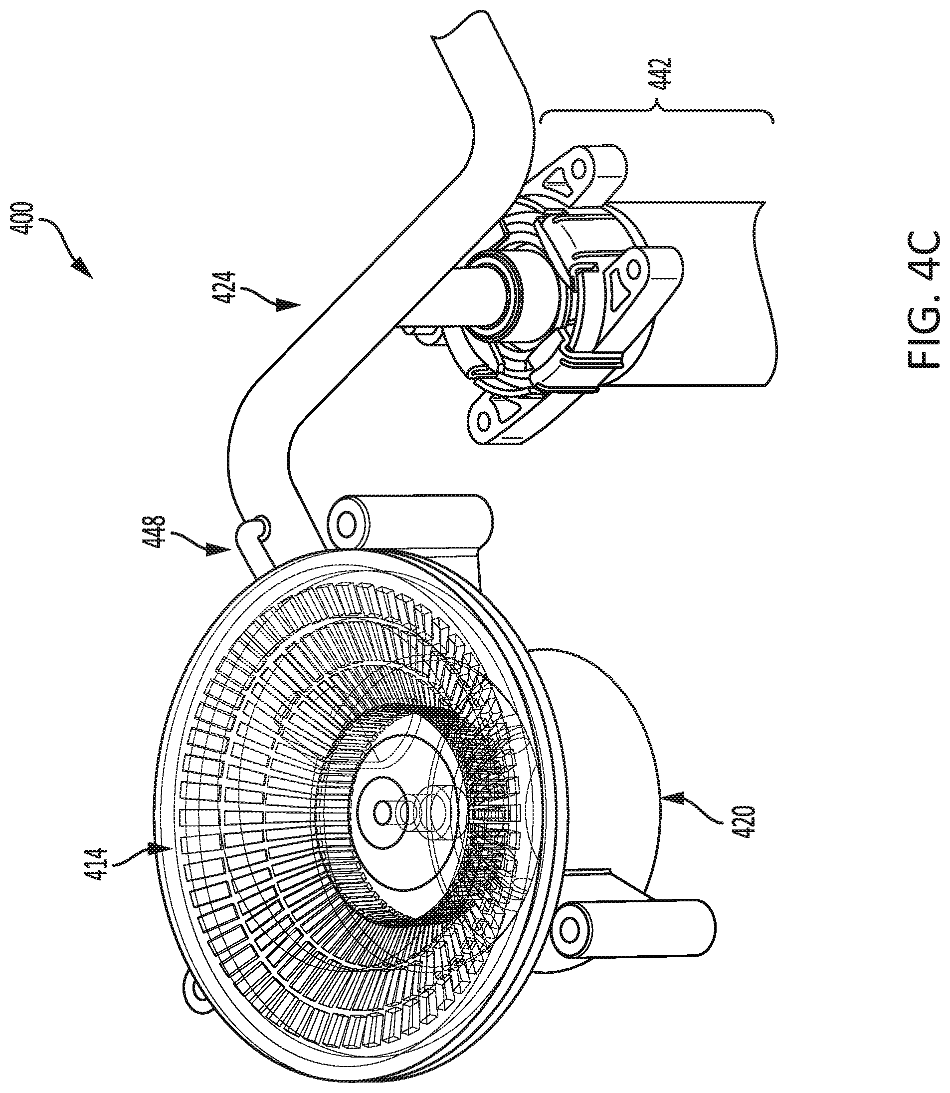
D00013

D00014
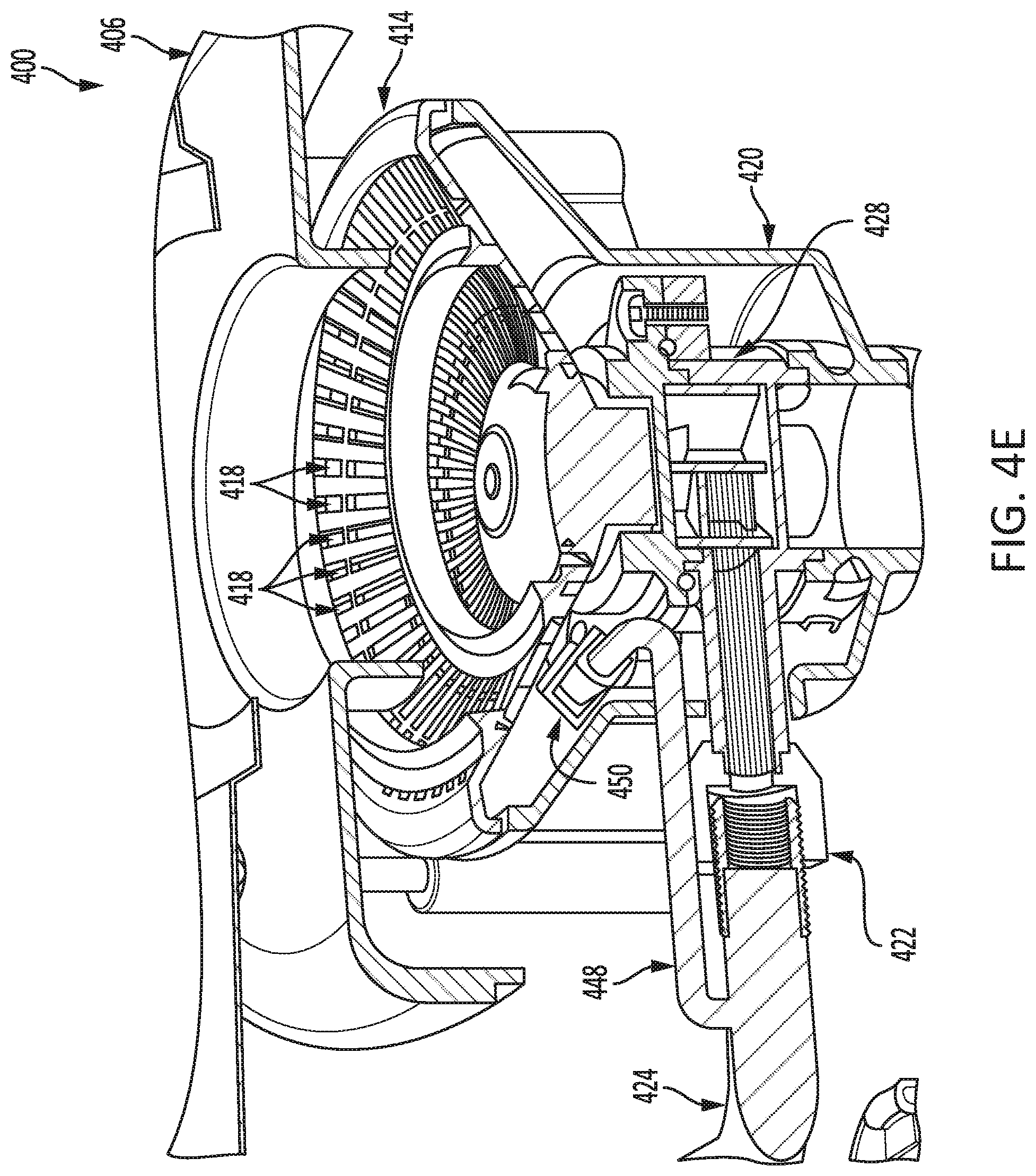
D00015

D00016

D00017

D00018

D00019
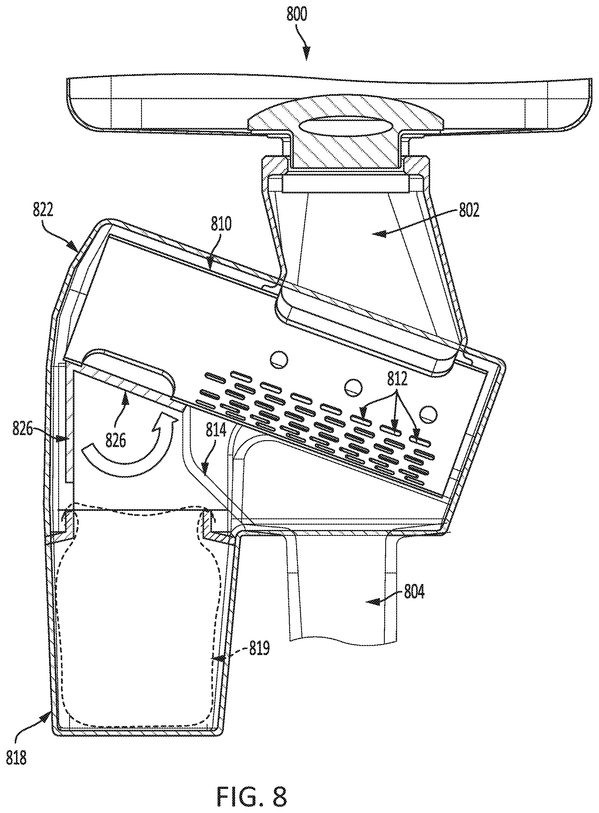
XML
uspto.report is an independent third-party trademark research tool that is not affiliated, endorsed, or sponsored by the United States Patent and Trademark Office (USPTO) or any other governmental organization. The information provided by uspto.report is based on publicly available data at the time of writing and is intended for informational purposes only.
While we strive to provide accurate and up-to-date information, we do not guarantee the accuracy, completeness, reliability, or suitability of the information displayed on this site. The use of this site is at your own risk. Any reliance you place on such information is therefore strictly at your own risk.
All official trademark data, including owner information, should be verified by visiting the official USPTO website at www.uspto.gov. This site is not intended to replace professional legal advice and should not be used as a substitute for consulting with a legal professional who is knowledgeable about trademark law.