System And Method Of Hot Water Recirculation Using A Bi-directional Cold-water Supply Line
Scafe; Rohan ; et al.
U.S. patent application number 16/289045 was filed with the patent office on 2020-09-03 for system and method of hot water recirculation using a bi-directional cold-water supply line. The applicant listed for this patent is Rinnai America Corporation. Invention is credited to Ansley Houston, Rohan Scafe.
| Application Number | 20200277760 16/289045 |
| Document ID | / |
| Family ID | 1000004081656 |
| Filed Date | 2020-09-03 |


| United States Patent Application | 20200277760 |
| Kind Code | A1 |
| Scafe; Rohan ; et al. | September 3, 2020 |
SYSTEM AND METHOD OF HOT WATER RECIRCULATION USING A BI-DIRECTIONAL COLD-WATER SUPPLY LINE
Abstract
A recirculation pump system provides the ability to recirculate water from a water heater outlet, back into a water heater inlet through a cold-water supply line. The recirculation pump system pumps heated water, which may have cooled to a sub-optimal temperature, into a water heater. The recirculation pump system provides the ability to use a plumbing network that does not contain a dedicated recirculation line. The recirculation pump system uses a water pump to circulate water, a temperature sensor to control system activation based on water temperature, and a check valve to control the direction of fluid flow. This recirculation pump system provides a minimally invasive way to install a recirculation system into a plumbing network that otherwise would not be able to accommodate recirculation functions, and service modern plumbing fixtures efficiently.
| Inventors: | Scafe; Rohan; (Peachtree City, GA) ; Houston; Ansley; (Peachtree City, GA) | ||||||||||
| Applicant: |
|
||||||||||
|---|---|---|---|---|---|---|---|---|---|---|---|
| Family ID: | 1000004081656 | ||||||||||
| Appl. No.: | 16/289045 | ||||||||||
| Filed: | February 28, 2019 |
| Current U.S. Class: | 1/1 |
| Current CPC Class: | F24H 1/101 20130101; E03B 7/045 20130101; F04B 49/02 20130101; F24D 17/0078 20130101; F04B 49/10 20130101; E03B 1/048 20130101 |
| International Class: | E03B 1/04 20060101 E03B001/04; F04B 49/02 20060101 F04B049/02; F04B 49/10 20060101 F04B049/10; F24D 17/00 20060101 F24D017/00; E03B 7/04 20060101 E03B007/04; F24H 1/10 20060101 F24H001/10 |
Claims
1. A recirculation pump system comprising: an inlet adapted to be fluidically connected to a hot-water supply line; an outlet adapted to be fluidically connected to a cold-water supply line; a temperature sensor configured to sense a temperature at the inlet; a water pump configured to pump water from the inlet to the outlet upon the temperature sensor detecting a lower threshold temperature; and a check valve configured to prevent water flow from the outlet to the inlet.
2. The recirculation pump system of claim 1 wherein the water pump is further configured to stop pumping water from the inlet to the outlet upon the temperature sensor detecting an upper threshold temperature.
3. The recirculation pump system of claim 1, wherein the upper threshold temperature is adjustable and may be set at 120 degrees Fahrenheit.
4. The recirculation pump system of claim 1, wherein the lower threshold temperature is adjustable and may be set at 110 degrees Fahrenheit.
5. The recirculation pump system of claim 1, wherein the check valve is configured to be positioned between the water pump and the outlet.
6. A water recirculation system comprising: a heat engine, having a cold-water inlet and a hot-water outlet, a hot-water supply line adapted to be fluidically connected to the hot-water outlet; an inlet adapted to be fluidically connected to the hot-water supply line; an outlet adapted to be fluidically connected to a cold-water supply line; the cold-water supply line adapted to be fluidically connected to the cold-water inlet; a temperature sensor configured to sense a temperature in the hot-water supply line; a water pump configured to pump water from the hot-water supply line to the cold-water supply line upon the temperature sensor detecting a lower threshold temperature; and a check valve configured to prevent water flow from the cold-water supply line to the water pump.
7. The water recirculation system of claim 6, wherein the water pump is further configured to stop pumping water in from the inlet to the outlet upon the temperature sensor detecting an upper threshold temperature.
8. The water recirculation system of claim 6, wherein the upper threshold temperature is adjustable and may be set at 120 degrees Fahrenheit.
9. The water recirculation system of claim 6, wherein the lower threshold temperature is adjustable and may be set at 110 degrees Fahrenheit.
10. The water recirculation system of claim 6, wherein the water pump is configured to circulate water from the hot-water supply line through the cold-water supply line to the cold-water inlet of the heat engine.
11. The water recirculation system of claim 6, wherein at least one or more plumbing fixtures are fluidically connected to the hot-water supply line and the cold-water supply line.
12. The water recirculation system of claim 6, wherein the water pump is coupled across the hot-water supply line, and the cold-water supply line at a furthest plumbing fixture from the hot-water outlet.
13. The water recirculation system of claim 11, wherein one or more plumbing fixtures are fluidically connected between the furthest plumbing fixture and the heat engine.
14. The water recirculation system of claim 10, wherein one or more of the plumbing fixtures are configured to operate on a cycle that draws an amount of water from the hot-water supply line that is less than an amount of water in the hot-water supply line between the hot-water outlet and the one or more of the plumbing fixtures.
15. The water recirculation system of claim 6, wherein the heat engine is a tankless water heater.
16. A method of recirculating hot water comprising: activating a water pump in a water recirculation system; circulating, by the water pump, water from a hot-water supply line through a cold-water supply line to a cold-water inlet of a heat engine inlet; circulating, by the water pump, water from a hot-water outlet of the heat engine to the hot-water supply line; measuring a temperature of the water in the hot-water supply line; deactivating the water pump when the water reaches an upper threshold temperature.
17. The method of recirculating hot water of claim 16, further comprising: reactivating the water pump when the water in the hot-water supply line falls below a lower threshold temperature.
18. The method of recirculating hot water of claim 16, wherein the upper threshold temperature is adjustable and may be set at 120 degrees Fahrenheit.
19. The method of recirculating hot water of claim 17, wherein the lower threshold temperature is adjustable and may be set at 110 degrees Fahrenheit.
20. The method of recirculating hot water of claim 16, wherein the heat engine is a tankless water heater.
Description
BACKGROUND
[0001] The need for heated fluids, and heated water, has long been recognized. Conventionally, water has been heated by water heaters containing heating elements. These water heaters are conventionally heated either electrically or with gas burners, where the heated water may be stored in a tank or reservoir. Additionally, such water heaters may be tankless, circulating hot water into a plumbing system without storing the water in a tank or reservoir. Water heaters are often used in private and commercial plumbing networks. Plumbing networks often require water to be continuously circulated into a heater to maintain a desired water temperature in hot-water supply lines.
[0002] Many modern businesses, such as Quick Service Restaurants (QSRs) for example, use existing water plumbing networks that are not particularly configured for hot-water recirculation. As such, these water plumbing networks often do not have a dedicated hot-water recirculation line to reheat lukewarm water that may sit in the plumbing network. But, many businesses use modern appliances and plumbing fixtures, which may require hot water at a set temperature. This set temperature may be necessary to meet safety requirements. For example, some businesses use automatic dish washers that use heated water to disinfect dirty dishes. Plumbing fixtures in such applications often require a small amount of water to operate, while drawing water from an extensive plumbing network.
[0003] As water sits in an extensive plumbing network, the water cools due to heat loss in the network's pipes, if the water is not recirculated. A plumbing network may contain a large amount of water, such as five gallons for example, between a water heater and a plumbing fixture. In some applications, a plumbing fixture may draw one to one and a half gallons of water in an operational cycle, causing it to only draw lukewarm water. As such, there is a need for a hot-water recirculation system that can operate in a water circulation network that does not contain a dedicated hot-water recirculation line.
SUMMARY
[0004] A first aspect of the disclosure provides a recirculation pump system. The recirculation pump system comprises an inlet adapted to be fluidically connected to a hot-water supply line. The recirculation pump system comprises an outlet adapted to be fluidically connected to a cold-water supply line. The recirculation pump system comprises a temperature sensor configured to sense a temperature at the inlet. The recirculation pump system comprises a water pump configured to pump water from the inlet to the outlet upon the temperature sensor detecting a lower threshold temperature. The recirculation system comprises a check valve configured to prevent water flow from the outlet to the inlet.
[0005] In some implementations of the first aspect of the disclosure, the water pump is further configured to stop pumping water from the inlet to the outlet upon the temperature sensor detecting an upper threshold temperature.
[0006] In some implementations of the first aspect of the disclosure, the upper threshold temperature is adjustable and may be set at 120 degrees Fahrenheit.
[0007] In some implementations of the first aspect of the disclosure, the lower threshold temperature is adjustable and may be set at 110 degrees Fahrenheit.
[0008] In some implementations of the first aspect of the disclosure, the check valve is configured to be positioned between the water pump and the outlet.
[0009] A second aspect of the disclosure describes a water recirculation system comprising a heat engine, having a cold-water inlet and a hot-water outlet. The water recirculation system comprises a hot-water supply line adapted to be fluidically connected to the hot-water outlet. The hot water recirculation system comprises an inlet adapted to be fluidically connected to the hot-water supply line. The hot water recirculation system comprises an outlet adapted to be fluidically connected to a cold-water supply line. The cold-water supply line is adapted to be fluidically connected to the cold-water inlet. The water recirculation system comprises a temperature sensor configured to sense a temperature in the hot-water supply line. The water recirculation system comprises a water pump configured to pump water from the hot-water supply line to the cold-water supply line upon the temperature sensor detecting a lower threshold temperature. The water recirculation system comprises a check valve configured to prevent water flow from the cold-water supply line to the water pump.
[0010] In some implementations of the second aspect of the disclosure, the water pump is further configured to stop pumping water in from the inlet to the outlet upon the temperature sensor detecting an upper threshold temperature.
[0011] In some implementations of the second aspect of the disclosure, the upper threshold temperature is adjustable and may be set at 120 degrees Fahrenheit.
[0012] In some implementations of the second aspect of the disclosure, the lower threshold temperature is adjustable and may be set at 110 degrees Fahrenheit.
[0013] In some implementations of the second aspect of the disclosure, the water pump is configured to circulate water from the hot-water supply line through the cold-water supply line to the cold-water inlet of the heat engine.
[0014] In some implementations of the second aspect of the disclosure, at least one or more plumbing fixtures are fluidically connected to the hot-water supply line and the cold-water supply line.
[0015] In some implementations of the second aspect of the disclosure, the water pump is coupled across the hot-water supply line, and the cold-water supply line at a furthest plumbing fixture from the hot-water outlet.
[0016] In some implementations of the second aspect of the disclosure, one or more plumbing fixtures are fluidically connected between the furthest plumbing fixture and the heat engine.
[0017] In some implementations of the second aspect of the disclosure, one or more of the plumbing fixtures are configured to operate on a cycle that draws an amount of water from the hot-water supply line that is less than an amount of water in the hot-water supply line between the hot-water outlet and the one or more of the plumbing fixtures.
[0018] In some implementations of the second aspect of the disclosure, the heat engine is a tankless water heater.
[0019] A third aspect of the disclosure describes a method of recirculating hot water comprising activating a water pump in a water recirculation system. The method of recirculating hot water comprises circulating, by the water pump, water from a hot-water supply line through a cold-water supply line to a cold-water inlet of a heat engine inlet. The method of recirculating water comprises circulating, by the water pump, water from a hot-water outlet of the heat engine to the hot-water supply line. The method of recirculating water comprises measuring a temperature of the water in the hot-water supply line. The method of recirculating water comprises deactivating the water pump when the water reaches an upper threshold temperature.
[0020] In some implementations of the third aspect of the disclosure, the method of recirculating water further comprises reactivating the water pump when the water in the hot-water supply line falls below a lower threshold temperature.
[0021] In some implementations of the third aspect of the disclosure, the upper threshold temperature is adjustable and may be set at 120 degrees Fahrenheit.
[0022] In some implementations of the third aspect of the disclosure, the lower threshold temperature is adjustable and may be set at 110 degrees Fahrenheit.
[0023] In some implementations of the third aspect of the disclosure, the heat engine is a tankless water heater.
BRIEF DESCRIPTION OF THE DRAWINGS
[0024] For a more complete understanding of the present disclosure, reference is now made to the following brief description, taken in connection with the accompanying drawings and detailed description, wherein like reference numerals represent like parts.
[0025] FIG. 1 illustrates a recirculation pump system diagram, showing individual components.
[0026] FIG. 2 illustrates a water recirculation system diagram.
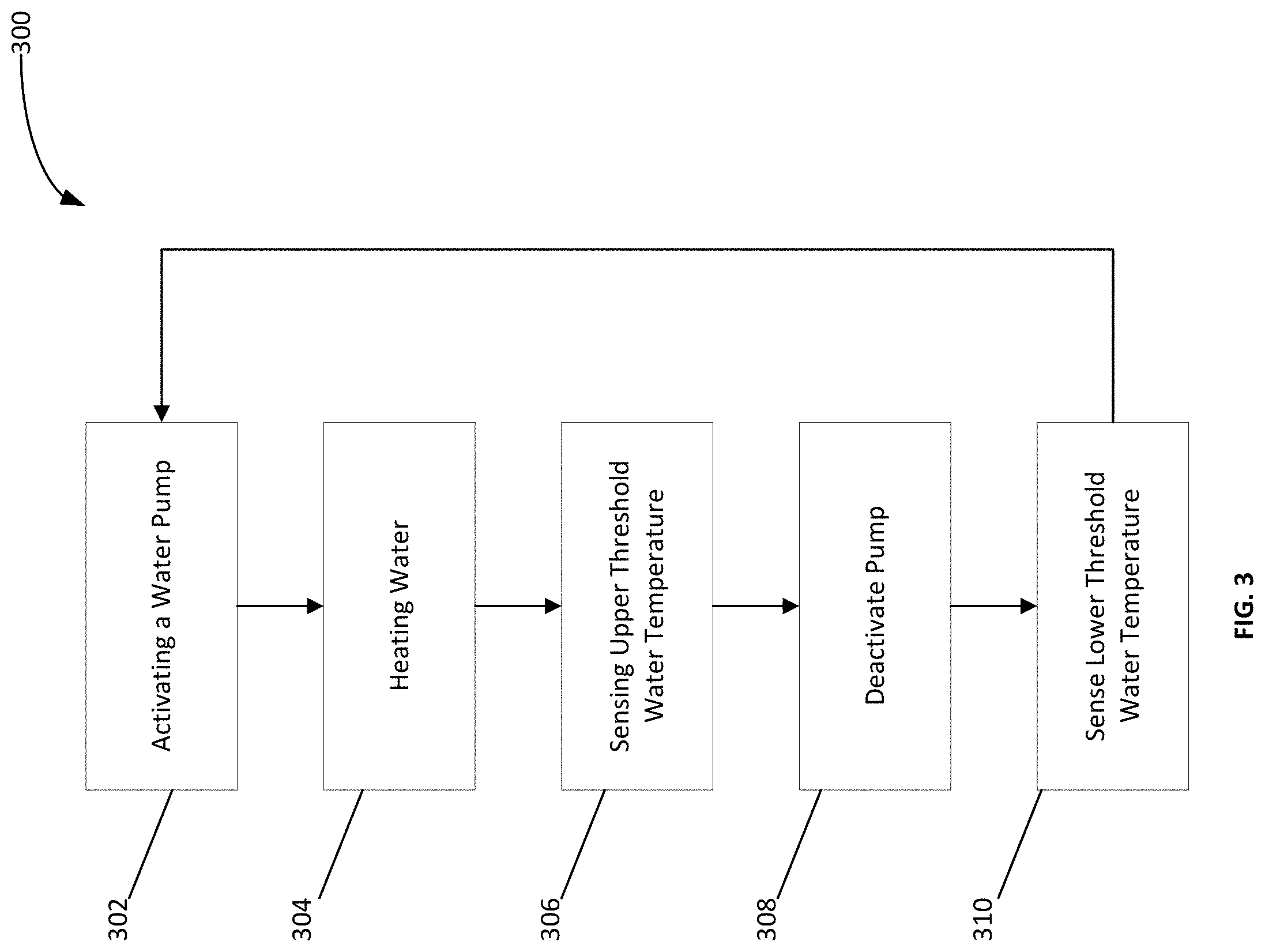
[0027] FIG. 3 illustrates a water recirculation system flow chart.
DETAILED DESCRIPTION
[0028] It should be understood at the outset that although illustrative implementations of one or more embodiments are illustrated below, the disclosed systems and methods may be implemented using any number of techniques, whether currently known or in existence. Like numbers represent like parts throughout the various figures, the description of which is not repeated for each figure. The disclosure should in no way be limited to the illustrative implementations, drawings, and techniques illustrated below, but may be modified within the scope of the appended claims along with their full scope of equivalents. Use of the phrase "and/or" indicates that any one or any combination of a list of options can be used. For example, "A, B, and/or C" means "A", or "B", or "C", or "A and B", or "A and C", or "B and C", or "A and B and C".
[0029] A recirculation pump system that comprises a temperature sensor, a water pump and a check valve provides the ability to recirculate water from a hot-water heater outlet, back into a water heater inlet through a cold-water supply line. Such hot-water bypass systems are particularly beneficial where a plumbing fixture requires hot water at a set temperature, such as an automatic dishwasher for example, is installed in an existing plumbing network.
[0030] In such systems, the existing plumbing network often does not contain a dedicated hot-water recirculation return line. A temperature sensor may connect to a hot-water supply line that contains heated water at a given time. The temperature sensor may sense when water temperature falls below a certain preset temperature. The temperature sensor may activate a water pump that is fluidically networked to circulate water up a cold-water supply line to a cold-water inlet on a water heater. A water circulation system may utilize the water pump at a furthest fixture from the water heater. When the water pump circulates the water, the water heater may activate and heat the circulating water to replenish the hot-water supply line with hot water at a heater set point temperature.
[0031] The temperature sensor may also sense an upper threshold water temperature and deactivate the water pump. This ensures that water hotter than the upper threshold water temperature is not circulated through the cold-water supply line in the water circulation system. When the water cools again to the preset temperature, due to heat loss in the plumbing network, the temperature sensor may activate the water pump again.
[0032] The preset temperature and the upper threshold temperature may be adjusted by a user. This allows a user to manage the temperature of hot-water entering the cold-water supply line and plumbing fixtures. As such, the adjustable preset temperature and the upper threshold temperature allows the hot-water recirculation system to provide hot water to fixtures at a desired temperature while preventing excess hot water from overwhelming the cold-water supply line. The temperature sensor further allows the hot-water recirculation system to maximize energy efficiency by only operating when necessary. The recirculation pump system may provide a minimally invasive way to install a hot-water recirculation system in a plumbing network that does into contain a hot-water recirculation line. This is important in applications where modern appliances may be installed in previously existing plumbing networks, which are not designed to otherwise accommodate such modern appliances and their heating requirements.
[0033] FIG. 1 illustrates a recirculation pump system 100, having a hot-water line 102. The hot-water line 102 being fluidically connected to a water pump 104 at a water pump inlet 104a. The water pump 104 also having an outlet 104b. The water pump outlet 104b may be fluidically connected to a check valve 106. The check valve 106 may be a spring check valve, such as a 3/4-inch spring check valve for example. The check valve 106 may be configured to limit the flow of water through the check valve 106 to a single direction--a direction from the hot-water line 102 to a cold-water supply line 108, as shown. The check valve 106 may have an inlet 106a and an outlet 106b wherein the check valve inlet 106a is fluidically connected to the water pump outlet 104b and the check valve outlet 106b is fluidically connected to the cold-water supply line 108. The cold-water supply line 108 may be configured to be fluidically connected to a cold-water source (shown in FIG. 2) and a heat engine cold-water inlet (shown in FIG. 2). In embodiments, the check valve 106 may be located between the water pump, 110 and the cold-water supply line 108 to restrict fluid flow to circulate out of and away from the water pump outlet 104b, such that no cold water may flow into the water pump outlet 104b.
[0034] The recirculation pump system 100 may be configured such that the recirculation pump system 100 is controlled by a temperature sensor 110. In embodiments, the temperature sensor 110 may be disposed about the hot-water line 102. The temperature sensor 110 may comprise a sensing element, such as a copper sensing element, that may sense the temperature of the hot-water line 102 through heat transfer through the hot water line 102. In some implementations, the temperature sensor 110 may also sense the water temperature by using a temperature probe to contact the water directly. Other variations of the temperature sensor 110 are contemplated by this disclosure.
[0035] The temperature sensor 110 may be programmable and may be electrically connected to the water pump 104, such that the water pump 104 may be activated when the temperature sensor 110 senses that the water has reached a lower threshold temperature. In embodiments, the lower threshold temperature of the water may be 110 degrees Fahrenheit. The temperature sensor 110 may also be configured to deactivate the water pump 104 when the temperature sensor 110 senses an upper threshold temperature. In embodiments, the upper threshold temperature may be 120 degrees Fahrenheit or greater. The temperature sensor may be a HONEYWELL AQUASTAT L6006C, for example. The upper threshold temperature and/or the lower threshold temperature may be programmatically adjusted on the temperature sensor 110 to ensure that hot water at a desired temperature is provided to fixtures at a desired temperature while preventing excess hot water from overwhelming the cold-water supply line.
[0036] FIG. 2 illustrates a water recirculation system 200 which is configured to integrate the recirculation pump system 100 (shown in FIG. 1) into a plumbing network. The recirculation pump system 100 has an inlet point 202 and an outlet point 204. The recirculation pump system inlet point 202 is fluidically connected to the hot-water line 102 and the recirculation pump system outlet point 204 is fluidically connected to the cold-water supply line 108. The cold-water supply line 108 is fluidically connected to at least one heat engine 206, at a water heater cold-water inlet 208. The at least one heat engine 206 may also have a heat engine hot-water outlet 210. The heat engine hot-water outlet 210 being fluidically connected to the hot-water line 102. The hot-water line 102 and the cold-water supply line 108 may each also be fluidically connected to at least one plumbing fixture 212a-f. The hot-water line 102 may route hot water from the at least one water heater 206 to the at least one plumbing fixture 212a-f. The cold-water supply line 108 may also route cold water to the at least one plumbing fixture 212a-f. The cold-water supply line 108 may also be fluidically connected to a cold-water source 214, such as a municipal water supply, that may provide cold water to the at least one plumbing fixture 212a-f and the heat engine cold-water inlet 208.
[0037] The recirculation pump system 100 may be disposed within the water recirculation system 200. When the temperature sensor 110 senses a water temperature in the hot-water line 102 that is below the lower threshold temperature, the water pump 104 may circulate water from the hot-water line 102 into the cold-water supply line 108 and through the heat engine 204. As such, the recirculated hot water may be fluidically connected to the cold-water source and the at least one heat engine 204. Therefore, the water recirculation system 200 uses the cold-water supply line 108 as a recirculation path for the hot water as well as a cold-water supply path. In embodiments, the at least one heat engine 204 may be a tankless water heater, or multiple tankless water heaters, each fluidically connected to the hot-water line 102 and the cold-water supply line 108. The at least one heat engine 204 may also be a tank water heater, that heats water and stores it in a hot-water storage tank (not shown).
[0038] FIG. 3 illustrates a flow diagram showing a process 300 for recirculating hot water through a water recirculation system with the water pump 104. At 302, the water pump 104 may be activated remotely or locally. A user may activate the water pump 104 at the time of desired operation, or a user may set a timer that activates the water pump 104 automatically at a set time. The water pump 104 may also be electronically connected to a temperature sensor 110, which may activate the water pump when it senses a certain temperature, or range of temperatures. In some embodiments the temperature sensor 110 may activate the water pump 104 upon sensing a lower threshold temperature. The lower threshold temperature is an adjustable temperature that may be a predetermined temperature set by a user or otherwise programmed into the temperature sensor 110.
[0039] The water pump 104 may circulate the water from the hot-water line 102 through the cold-water supply line 108 and into the at least one heat engine 204. The at least one heat engine 204 may heat the water circulating therethrough 304. The at least one heat engine 204 may be a water heater. In embodiments, the at least one heat engine 204 may be a tankless water heater. The at least one heat engine 204 may transfer heat to the water that is circulating through it by conduction, or some other form of heat transfer such as convection or radiation. The hot water may then be circulated out of the at least one heat engine 204 into the hot-water line 102 at a set point temperature.
[0040] A temperature sensor 110 may sense the temperature of the hot water 306, by using a sensing element to take the temperature of a surface of the hot-water line 102. In embodiments, the temperature sensor may also take the temperature of the water in the hot-water line 102 directly, using a probe disposed within hot-water line 102. In embodiments, the temperature sensor may deactivate the water pump 104 when the temperature sensor 110 senses an upper threshold temperature 306. The upper threshold temperature is an adjustable temperature that may be a predetermined temperature set by a user or otherwise programmed into the temperature sensor 110. The temperature sensor 110 may be electronically connected to the water pump 104, such that the temperature sensor 110 signals the water pump 104 to deactivate when it senses the upper threshold temperature.
[0041] The temperature sensor 110 may sense a lower threshold temperature 308. In embodiments the temperature sensor 110 may activate the water pump 104 upon sensing a lower threshold temperature. The temperature sensor 110 may reactivate the water pump as shown at 302. The water recirculation system 200 may continue this cycle as long as a user intends to maintain hot water in the water recirculation system 200.
[0042] While several embodiments have been provided in the present disclosure, it should be understood that the disclosed systems and methods may be embodied in many other specific forms without departing from the spirit or scope of the present disclosure. The present examples are to be considered as illustrative and not restrictive, and the intention is not to be limited to the details given herein. For example, the various elements or components may be combined or integrated in another system or certain features may be omitted or not implemented.
[0043] Also, techniques, systems, subsystems, and methods described and illustrated in the various embodiments as discrete or separate may be combined or integrated with other systems, modules, techniques, or methods without departing from the scope of the present disclosure. Other items shown or discussed as directly coupled or communicating with each other may be indirectly coupled or communicating through some interface, device, or intermediate component, whether electrically, mechanically, or otherwise. Other examples of changes, substitutions, and alterations are ascertainable by one skilled in the art and could be made without departing from the spirit and scope disclosed herein.
* * * * *
D00000
D00001
D00002
D00003
XML
uspto.report is an independent third-party trademark research tool that is not affiliated, endorsed, or sponsored by the United States Patent and Trademark Office (USPTO) or any other governmental organization. The information provided by uspto.report is based on publicly available data at the time of writing and is intended for informational purposes only.
While we strive to provide accurate and up-to-date information, we do not guarantee the accuracy, completeness, reliability, or suitability of the information displayed on this site. The use of this site is at your own risk. Any reliance you place on such information is therefore strictly at your own risk.
All official trademark data, including owner information, should be verified by visiting the official USPTO website at www.uspto.gov. This site is not intended to replace professional legal advice and should not be used as a substitute for consulting with a legal professional who is knowledgeable about trademark law.