Transport Closure, A Packaging Container Comprising The Transport Closure And A Method For Removing The Transport Closure From t
Holka; Simon ; et al.
U.S. patent application number 16/647308 was filed with the patent office on 2020-09-03 for transport closure, a packaging container comprising the transport closure and a method for removing the transport closure from t. This patent application is currently assigned to &R Carton Lund Aktiebolag. The applicant listed for this patent is &R Carton Lund Aktiebolag. Invention is credited to Kajsa Dahlin, Simon Holka, Fredrik Konstenius, Eva Sunning.
| Application Number | 20200277101 16/647308 |
| Document ID | / |
| Family ID | 1000004859209 |
| Filed Date | 2020-09-03 |


| United States Patent Application | 20200277101 |
| Kind Code | A1 |
| Holka; Simon ; et al. | September 3, 2020 |
Transport Closure, A Packaging Container Comprising The Transport Closure And A Method For Removing The Transport Closure From the Packaging Container
Abstract
The present disclosure relates to a transport closure (1) for use in a packaging container (10) for bulk solids. The transport closure includes a laminate of a first layer (2) and a second layer (3). The first layer (2) is delimited by a first layer peripheral edge (4) and the second layer (3) is delimited by a second layer peripheral edge (5). The second layer (3) comprises or consists of a weldable material and the first layer (2) has higher tear strength than the second layer (2). The first layer (3) is provided with a weakening line (6) defining a pull-tab (7) in the first layer (3) and having a first and a second base point (6a,6b). The base points (6a,6b) are arranged at a base end (7b) of the pull-tab (7), opposite to a gripping end (7a) of the pull-tab (7).
| Inventors: | Holka; Simon; (Staffanstorp, SE) ; Konstenius; Fredrik; (Lund, SE) ; Dahlin; Kajsa; (Vallingby, SE) ; Sunning; Eva; (Annelov, SE) | ||||||||||
| Applicant: |
|
||||||||||
|---|---|---|---|---|---|---|---|---|---|---|---|
| Assignee: | &R Carton Lund
Aktiebolag Lund SE |
||||||||||
| Family ID: | 1000004859209 | ||||||||||
| Appl. No.: | 16/647308 | ||||||||||
| Filed: | September 13, 2018 | ||||||||||
| PCT Filed: | September 13, 2018 | ||||||||||
| PCT NO: | PCT/SE2018/050927 | ||||||||||
| 371 Date: | March 13, 2020 |
| Current U.S. Class: | 1/1 |
| Current CPC Class: | B65D 2517/0086 20130101; B65D 17/4011 20180101; B65D 2517/0016 20130101; B65D 77/2056 20130101; B65D 2517/0082 20130101; B65D 2517/0061 20130101; B65D 2577/2058 20130101; B65D 51/20 20130101 |
| International Class: | B65D 17/28 20060101 B65D017/28; B65D 51/20 20060101 B65D051/20; B65D 77/20 20060101 B65D077/20 |
Foreign Application Data
| Date | Code | Application Number |
|---|---|---|
| Sep 14, 2017 | SE | 1751125-4 |
Claims
1. A transport closure for use in a packaging container for bulk solids, said transport closure comprising or consisting of a laminate of a first layer and a second layer, said first layer being delimited by a first layer peripheral edge, said second layer being delimited by a second layer peripheral edge, said second layer comprising or consisting of a weldable material and said first layer having a higher tear strength than said second layer; wherein said first layer is provided with a weakening line defining a pull-tab in said first layer and having a first and a second base point, said base points being arranged at a base end of said pull-tab, opposite to a gripping end of said pull-tab, and at a distance d1 and d2 respectively, of from 1 to 30 mm from said first peripheral edge, wherein said weakening line forms one or both of a first and second weakening line leg extending from said one or both of the first and said second base point, respectively, and alongside with said first layer peripheral edge and that said second layer peripheral edge extends beyond said first layer peripheral edge around the perimeter of said transport closure forming a transport closure welding collar.
2. The transport closure according to claim 1, wherein said first layer is a paperboard layer, a metal disc, a plastic disc or a laminate thereof.
3. The transport closure according to claim 1, wherein said first layer has a thickness of from 5 to 2000 .mu.m or from 20-500 .mu.m.
4. The transport closure according to claim 1, wherein said second layer comprises or consist of a plastic film or a metal foil, such as Aluminum foil.
5. The transport closure according to claim 1, characterized in that said second layer has a thickness from 2 .mu.m to 500 .mu.m such as from 5 to 100 .mu.m.
6. The transport closure according to claim 1, wherein said first layer has a stiffness that is greater than said second layer.
7. The transport closure according to claim 1, wherein said second layer peripheral edge extends beyond said first layer peripheral edge by a distance of from 1 to 25-, such as from 2 to 10 mm.
8. The transport closure according to claim 1, wherein said first and second base points at said base end are arranged at a distance from each other of each least 3 mm, such as from 8 to 25 mm.
9. The transport closure according to claim 1, wherein said first layer comprises a corner portion and that said pull-tab is arranged in said corner portion.
10. The transport closure according to claim 1, wherein said distances d1 and d2 for said first and said second base point respectively, of said weakening line each are arranged no more than 10 mm from said first layer peripheral edge.
11. The transport closure according to claim 1, wherein said pull-tab has a V-shape, O-shape, U-shape or a modified U-shape.
12. The transport closure according to claim 1, wherein a first push-in area is defined in or by said first layer and that said push-in area is provided at said gripping end of said pull-tab.
13. A packaging container for bulk solids being closed by the transport closure of claim 1, said container comprising a tubular container body with a top end with a top opening and a bottom end with a bottom opening comprising a container bottom, said container body having an inner surface facing towards an inner compartment in said packaging container and an outer surface facing away from said inner compartment, said packaging container being closed at said top opening by said transport closure said welding collar being welded to said inner surface of said container body.
14. A method for removing the transport closure from said packaging container according to claim 13, the method comprising the steps of: a) gripping said pull-tab at said gripping end; b) pulling said pull-tab along said weakening line and towards said base end and said first layer peripheral edge; c) lifting said pull-tab slightly upwards until said second layer breaks and detaches from said inner surface of said container body; and d) pulling said pull-tab upwards and backwards from said base end such that said second layer breaks and detaches from said inner surface at said welding seal and along said one or both of a first and second weakening line leg along the peripheral edges of said first layer until said transport closure is removed from said top opening and leaving less than 0.5 mm of said second layer extending into said top opening of said container body.
15. The method for removing a transport closure from a packaging container according to claim 14, the method further comprising the step of: a1) applying pressure at a first push-in area defined in or by said first layer and provided at said gripping end of said pull-tab and thereby inclining said gripping end away from the transport closure to define a gap under said gripping end.
Description
TECHNICAL FIELD
[0001] The present disclosure pertains to a transport closure for use in a packaging container for bulk solids. More specifically, the present disclosure pertains to a transport closure having improved opening characteristics. The present disclosure also pertains to a packaging container comprising the transport closure and a method for removing the transport closure from the packaging container.
BACKGROUND
[0002] When packaging consumer goods, and in particular when packaging bulk solids, such as dry flowable consumer goods or other consumer goods sensitive to moisture, it is common to use rigid paperboard packaging containers which serve as protective transport and storage containers at the retail end and as storage and dispensing containers at the consumer end. Such paperboard containers are usually provided with an openable and closable lid, and with an inner removable or breakable transport closure which keeps the contents fresh and protected against moisture and contamination up until the container is opened by a consumer. The breakable transports closures may be welded to the container wall inner surface to improve the protection of the content during transport and storage. This may be of particular importance for moisture sensitive contents.
[0003] In order to gain access to the content, the packaging container transports closures may be provided with tear-open parts which are opened by using a push-tab and/or a pull-tab to tear away a central part of the transport closure. However, upon removal of such tear-open parts, an outer border of the transport closure, attached to the inner surface of the container body, remains protruding into the container body opening. This may cause difficulties for packaging containers which are sized and shaped to accommodate a particular type of content and which have top openings being specifically size-adapted in respect to the content of the packaging container. An example of a container of this type is a packaging container for snacks such as potato chips wherein the chips are piled up in an upwards standing pile. Furthermore, the remaining border of the transport closure reduces the opening size of the packaging container opening, thereby obstructing access to the packaged contents, such as when scooping powdered contents from a container or when trying to pour contents out of a container. In particular when the packaged goods is a particulate product, such as a dry infant formula product, some of the packaged product may be caught on the transport closure border and may cause the container to appear less hygienic to a user.
[0004] Accordingly, it is an object of the present disclosure to offer an improved, easy-open, and less obstructive transport closure for a packaging container, an improved packaging container and method for opening a packaging container.
SUMMARY
[0005] The above and other objects may be provided by a transport closure according to claim 1, a packaging container according to 13 and a method according to 14. Further embodiments are set out in the dependent claims, in the following description and in the drawings.
[0006] As such and according to a first aspect, the present disclosure relates to a transport closure for use in a packaging container for bulk solids. The transport closure comprises or consists of a laminate of a first layer and a second layer. The first layer is delimited by a first layer peripheral edge and the second layer is delimited by a second layer peripheral edge. The second layer comprises or consists of a weldable material and the first layer has higher tear strength than the second layer. The first layer is provided with a weakening line defining a pull-tab in the first layer and having a first and a second base point. The base points are arranged at a base end of the pull-tab, opposite to a gripping end of the pull-tab. Each of the base ends are arranged at a distance, d1 and d2 respectively, of from 1 to 30 mm from the first peripheral edge. The weakening line forms a first and/or a second weakening line leg(s) extending from the first and/or second base point(s), respectively, and alongside with the first layer peripheral edge. The second layer peripheral edge extends beyond the first layer peripheral edge around the perimeter of the transport closure forming a transport closure welding collar.
[0007] By "weakening means" is meant that the first layer of the transport closure is provided with a continuous slit, a series of discontinuous slits, perforations or the like, allowing rupture of the transport closure at a predefined location such that rupture will take place along a predefined separation line.
[0008] Packaging containers having high demands on gas impermeability during transport and storage are often provided with a transport closure in some form. For various reasons there may be a desire to place such transport closures at a distance from the packaging container upper edge, and such transport closure may therefore be welded to the inner surface of the packaging container to provide a gas impermeable seal between the transport closure and the packaging container. Transport closures therefore need to be weldable. The fact that the transport closure is provided as a laminate of a first layer and a second layer, the first layer having a higher tear strength than the second weldable layer, provides the transport closure with a higher resistance to unintentional breakage of the transport closure. Furthermore, when opening a packaging container provided with the transport closure as disclosed herein, is has been found possible to accomplish an almost complete removal of the transport closure as the peripheral edge of the first layer functions as a tear guide upon tearing of the pull-tab and removal of the transport closure from the container top opening. The peripheral edge of the first layer acts as a tear initiation means by cutting or punching a hole in the second layer at the part of the peripheral edge of the first layer which is located at the base of the pull-tab. The base of the pull-tab is defined between the base-points of the weakening line defining the pull-tab. After the initial rupture of the second layer, by continuing to pull away the transport closure from the container opening, the peripheral edge will serve to propagate the tear in the second layer along the peripheral edge of the first layer.
[0009] The ratio of the tear strength of the first layer to the second layer is 1.1 or more, in both CD and MD directions. The ratio of the tear strength of the first layer to the second layer may be from 1.1 or more, such as 1.5 or more, such as 2 or more, such as 4 or more, such as up to 1000.
[0010] The tear strength is measured according to the standard method DIN 53363 for determining tear resistance of plastic film and sheeting by the trouser tear method and is given as max tear strength (N).
[0011] The second layer may have a tear strength of from 1 to 100 N, such as 5 to 30 N, in both CD and MD direction.
[0012] As set out herein, the consumer may upon removal of the transport closure, grip and pull the pull-tab provided in the first layer, along the weakening line and towards the base end of the pull-tab. The first pulling action serves to free the pull-tab from the remainder of the first layer and to raise the pull-tab out of the plane of the first layer. Upon pulling of the pull-tab towards the base end, a pressure is applied at the base end of the pull-tab. The user may further enhance the pressure applied at the base end of the pull-tab, by pushing the transport closure downward, into the container within an area at the base end of the pull-tab. The pressure arising at the base end of the pull-tab during the first pulling action initiates or contributes to initiate a rupture in the second layer at the peripheral edge of the first layer. This rupture in the second layer will propagate along the periphery of first layer peripheral edge functioning as a tearing guide, when further pulling the pull-tab upwards and backwards from the base end until the transport closure is almost completely removed from the top opening. The only remains of the transport closure along the inner wall of the packaging container will be the transport closure welding collar formed only by the second layer. Consequently, only a very thin residual egde of the welding collar is left around the periphery of the inner wall of the container.
[0013] Optionally, the first layer comprises or consists of a paperboard or paper layer, a metal layer, a plastic layer, or any combination thereof.
[0014] Optionally, the first layer has a thickness of from 5 to 2000 .mu.m, such as from 20 to 500 .mu.m. This provides stiffness to the first layer and distinct peripheral edge forming a good tearing guide for the second material layer upon removal of the transport closure.
[0015] Optionally, the second layer comprises or consists of a plastic film or a metal foil, such as Al foil, or a combination thereof.
[0016] Optionally, the second layer has a thickness from 2 .mu.m to 500 .mu.m, such as from 5 .mu.m to 100 .mu.m. The fact that the second layer has a thickness of from 2 .mu.m to 500 .mu.m, such as from 5 .mu.m to 100 .mu.m gives a low tearing strength upon opening of the transport closure, while still enabling a good welding seal against an inner wall of a packaging container. Furthermore, a thin second layer is beneficial as it leaves a minimal amount of residual material on the container wall after removal of the transport closure.
[0017] Optionally, the first layer has a stiffness that is greater than said second layer.
[0018] Optionally, the second layer peripheral edge extends beyond the first layer peripheral edge by a distance of from 1 mm to 25 mm, such as from 2 mm to 25 mm or 2 mm to 10 mm. The fact that the second layer peripheral edge extends beyond the first layer peripheral edge by a distance of from 1 mm to 25 mm, provides the transport closure with a peripheral welding area for securely attaching the transport closure by welding to the inner walls of a packaging container.
[0019] Optionally, the first and second base points at the pull-tab base end are arranged at a distance from each other of each least 3 mm, such as at least 8 mm. The base line of the pull-tab is the distance between the base points, i.e. the width of the pull-tab at the base points, which may be smaller than the width of the pull-tab at the gripping end of the pull-tab, thereby concentrating the traction force creating when pulling at the pull-tab within a limited area at the base of the pull-tab.
[0020] The base end of the pull-tab may be located at any portion of the peripheral edge of the first layer, such as at a straight or curved portion of the peripheral edge of the first layer.
[0021] Optionally, the first layer comprises a corner portion and the pull-tab is arranged with the base end in the first layer corner portion. When arranging the pull-tab, and more specifically the base end of the pull-tab, in a corner portion, the tearing direction for the second layer along the peripheral edges of the first layer will to some extend correspond to the tearing movement of the consumer hand, compared to when the pull-tab is arranged at a side edge and the tearing direction initially will be directed outwardly and essentially 90 degrees in relation to the tearing movement of the consumer hand.
[0022] Alternatively, the pull-tab is arranged with the base end between two corner portions in the first layer, such as between two corner portions in a generally rectangular transport closure having four corner portions.
[0023] A corner portion, as implied herein, is a curved corner portion having a radius of curvature of from 7-65 mm, preferably 10-65 mm, more preferably 15-30 mm.
[0024] Optionally, the first layer is laminated to the second layer along at least one welding joint extending in parallel with the first layer peripheral edges, such as for example at a distance of from 1 to 10 mm from the first layer peripheral edges. The fact that the first layer is laminated to the second layer by at least one welding joint extending in parallel with the first layer peripheral edges, such as for example at a distance of from 1 to 10 mm from the first layer peripheral edges, efficiently promotes the rupture of the second material layer along the first layer peripheral edges. The first layer may be laminated to the second layer essentially only by a welding joint extending along and at the first layer peripheral edges, providing the transport closure with a slight bulge within the area which is free from attachments between the first and second layers, such that the force is focused to the area of rupture and separation of the transport closure from the inner wall of a packaging container. The outwardly bulging non-attached part of the first layer may also serve to facilitate gripping and freeing of the pull-tab from the remainder of the first layer. It may be advantageous that a slit is formed through the first layer at the gripping end of the pull-tab, to allow a user to insert a finger or a finger nail through the slit to get an initial hold of the gripping end of the pull-tab. The bulging part of the first layer aids in widening the gripping end slit, to further facilitate gripping of the pull-tab.
[0025] Optionally, the distances d1 and d2 for the first and the second base points of the weakening line are each from 1 to 10 mm from the first layer peripheral edge.
[0026] By "base points" herein is meant the points of the weakening lines forming the end points of the pull-tab contour and are located at the base end of the pull-tab. The base points are thus the points along the contour of the pull-tab being closest to the peripheral edge of the first layer. The weakening line additionally forms one or two weakening line leg(s) extending from the pull-tab base end(s) and alongside with the peripheral edges of the first layer. The one or two weakening line leg(s) may end with an inwards curve or bend.
[0027] The weakening line leg(s) extending from the base points, and in parallel with the peripheral edges of the first layer, may reduce the force required to break the second layer at the first layer peripheral edges, as the first layer is separated from the second layer at the weakening line leg(s). Therefore, only breaking and pulling of the material between the first layer peripheral edges and the weakening line leg(s) upon removal of the transport closure is required for complete removal of the transport closure.
[0028] Optionally, the pull-tab has a V-shape, U-shape, O-shape or a modified U-shape.
[0029] Optionally, a push-in area, provided at the gripping end of the pull-tab, is defined in the first layer. Optionally, the push-in area may be formed by the absence of the first layer material in an area at the gripping end of the pull-tab, such as by means of cutting out or punching out an area of the first layer prior to lamination to the second layer. Alternatively, the push-in area may be identified at the gripping end of the pull-tab by any identification means such as print, embossings, perforations, scorings, colouring or any combination of identification means.
[0030] The fact that a push-in area is defined in the first layer and that the push-in area is provided at the gripping end of the pull-tab provides instructions to the consumer to apply pressure at the push-in area. By applying pressure at the push-in area, the gripping end of the pull-tab will be inclined away from the transport closure and define a gap under the gripping end, facilitating grasping of the pull-tab gripping end.
[0031] In a corresponding manner, a second push-in area may be defined in the first layer at the base end of the pull-tab. A push-in area at the base end of the pull-tab may be identified as set out above, by any identification means such as print, embossings, perforations, scorings, colouring or any combination of identification means.
[0032] According to a second aspect, the present disclosure relates to a packaging container for bulk solids. The container comprises a tubular container body with a top end with a top opening and a bottom end with a bottom opening comprising a container bottom. The container body has an inner surface facing towards an inner compartment in the packaging container and an outer surface facing away from the inner compartment. The packaging container is closed at the top opening by a removable transport closure according to the first aspect of the present disclosure and the welding collar is welded to the inner surface of the container body.
[0033] According to a third aspect, the present disclosure relates to a method for removing a transport closure according to the first aspect from a packaging container according to the second aspect. The method comprises the steps of: [0034] a) gripping the pull-tab at the gripping end; [0035] b) pulling the pull-tab along the weakening line and towards the base end and the first layer peripheral edge; [0036] c) lifting the pull-tab upwards until the second layer breaks and detaches from the inner surface of the container body; and [0037] d) pulling the pull-tab slightly upwards and backwards from the base end such that the second layer breaks and detaches from the inner surface at the welding seal and along the first and/or second weakening line leg(s) along the peripheral edges of the first layer until the transport closure is removed from the top opening and leaving less than 0.5 mm of the first layer extending into the top opening of the container body.
[0038] During step c) the lifting of the pull-tab in the gripping end will push the base end of the pull-tab inwardly at a second push-in area defined in the second layer at the first layer peripheral edge and thereby break the second layer initiate a crack propagation along the peripheral edges of the first layer.
[0039] Optionally, the method further comprises the step of: [0040] a1) applying pressure at a first push-in area defined in the first layer and provided at the gripping end of the pull-tab and thereby inclining the gripping end of the pull-tab away from the transport closure to define a gap under the gripping end.
[0041] As used herein, the term "bulk solids" refers to a solid material. The bulk material may be dry or moist. The bulk solids may be in the form of particles, granules, grinds, plant fragments, short fibres; flakes, seeds, formed pieces of material such as pasta, etc. The bulk solids which are suitable for packaging in the packaging containers as disclosed herein may be flowable, which means that a desired amount of the product may be poured or scooped out of the packaging container, or in the form of discreet pieces of material allowing removal of only part of the content in the packaging container.
[0042] The packaging container as disclosed herein may be a container for alimentary products such as infant formula, coffee; tea, rice, pasta, chips, flour, sugar, cereals, soup powder, custard powder, or the like. Alternatively, the bulk solids may be non-alimentary, such as tobacco, detergent, fertilizer, chemicals or the like.
BRIEF DESCRIPTION OF THE DRAWINGS
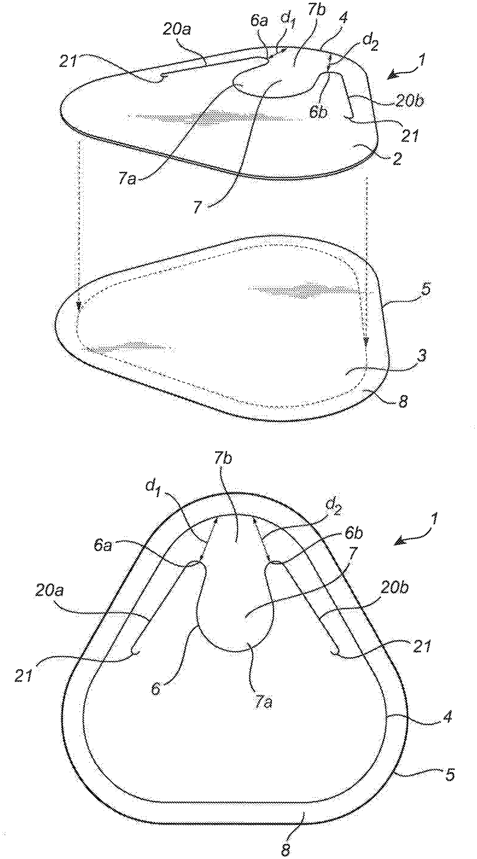
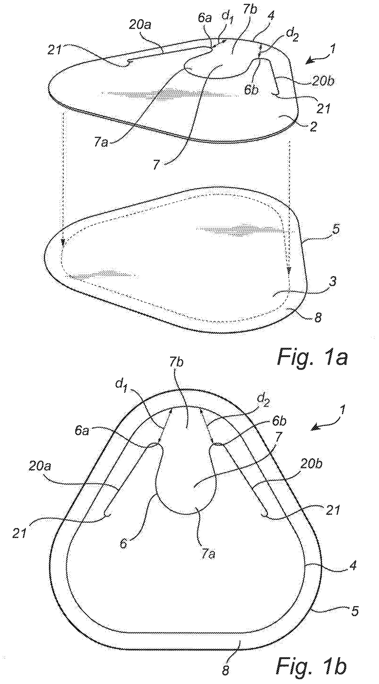
[0043] FIGS. 1a-1d illustrate embodiments of a transport closure according to the present disclosure;
[0044] FIGS. 2a-2b illustrate a packaging container comprising a transport closure according to the present disclosure, and;
[0045] FIGS. 2c-2e illustrate steps for removing a transport closure from a packaging container according to the present disclosure.
DETAILED DESCRIPTION
[0046] It is to be understood that the drawings are schematic and that individual components, such as layers of materials are not necessarily drawn to scale. The transport closures and the packaging containers shown in the figures are provided as examples only and should not be considered limiting to the invention. Accordingly, the scope of the invention is determined solely by the scope of the appended claims.
[0047] FIGS. 1a-d illustrate transport closures for use in a paperboard packaging container for bulk solids according to the first aspect of the present disclosure. The particular shape of the transport closure 1 shown in the figures should not be considered limiting to the invention. Accordingly, a transport closure produced according to the invention may have any useful shape or size, such as circular, rectangular (including square) or any useful polygonal shape. It is to be understood that the polygonal shapes as implied herein are modified polygonal shapes having rounded corner portions.
[0048] Furthermore, the transport closures shown in the Figs. have first and second layers with identical shapes, only differing in size resulting in a welding collar having uniform width around the peripheral edge of the first layer. It is to be understood that although such embodiments are generally preferred, embodiments where the width of the welding collar varies along the peripheral edge of the first layer may also be useful. By way of example, the welding collar may have a greater width at the corner portions of a transport closure, to provide more weldable material for ensuring a tight seal at the corner. In some applications, such as when the radius of curvature of the corner portion is small, it may instead be desirable that the welding collar has a smaller width at the corner portions, to avoid creation of wrinkles when welding the transport seal to a container wall.
[0049] FIG. 1a illustrates the first layer 2 and the second layer 3 prior to lamination and formation of a transport closure 1. The transport closure 1 comprises or consists of a laminate of the first layer 2 and the second layer, as illustrated in FIG. 1b. The first layer 2 is delimited by a first layer peripheral edge 4 and the second layer 3 is delimited by a second layer peripheral edge 5. The first layer 2 has an essentially triangular shape with side edges 13 and three rounded corner portions 12, and the second layer 3 has the same shape as the first layer 2. As further illustrated in FIGS. 1a and 1b, the second layer peripheral edge 5 extends beyond the first layer peripheral edge 4, forming a transport closure welding collar 8. Thus, the second layer 3 has a larger surface area than the first layer 2. The second layer 3 comprises or consists of a weldable material and the first layer 2 has higher tear strength and preferably also a higher stiffness than the second layer 3. The first layer 2 is provided with a weakening line 6 defining a pull-tab 7 in the first layer 2. The pull-tab 7 which has a modified U-shape, has a gripping end 7a and a base end 7b. The weakening line 6 comprises two base points 6a,6b arranged at the base end 7b of the pull-tab 7, at the points along the part of the weakening line forming the pull-tab 7 contour which are arranged at the shortest distance from the first layer peripheral edge 4. The first base point 6a is arranged at a distance d1 from the first layer peripheral edge 4 and the second base point 6b is arranged at a distance d2 from the first layer peripheral edge 4. The distance between the first base point 6a and the second base point 6b may be 3 mm or more, such as from 8 mm to 25 mm.
[0050] The weakening line 6 is additionally formed such as to provide a first and a second weakening line leg 20a,20b extending from the first and the second pull-tab base ends 6a,6b respectively and parallel with the first layer peripheral edge 4. The weakening line legs 20a,20b each end with an inwards bend 20. The inwardly curved bend 20 supports correct breaking and tearing along the first layer peripheral edges 4 and prevents tearing in an undesired direction.
[0051] FIG. 1c illustrates a transport closure 1 similar to the transport closure 1 illustrated in FIGS. 1a-b, but is additionally provided with a first push-in area 9 defined in the first layer 2. The first push-in area 9 is formed by the absence of the first layer material 2 in an area at the gripping end 7a of the pull-tab 7 and has been formed by punching out an area of the first layer 2 prior to lamination to the second layer 3. Other ways of identifying the first push-in area 9 may be by printing or embossing or any other suitable means, as set out herein which may provide instructions to the consumer to apply pressure at the first push-in area 9 so that the gripping end 7a is inclined away from the transport closure 1 and a gap is formed under the gripping end 7a facilitating grasping of the pull-tab 7.
[0052] FIG. 1d illustrates a further transport closure 1 according to the present disclosure. The transport closure 1 is a laminate of the first layer 2 and the second layer. The first layer 2 is delimited by a first layer peripheral edge 4 and the second layer 3 is delimited by a second layer peripheral edge 5. The first layer 2 has an essentially triangular shape with side edges 13 and three rounded corner portions 12. It should however be noted that the transport closure 1 and each of the first and the second layers 2,3 may have other shapes such as for example round, oval, square, square with rounded edges, rectangular and rectangular with rounded edges, as set out herein. In FIG. 1d, the second layer 3 has the same shape as the first layer 2. The second layer peripheral edge 5 extends beyond the first layer peripheral edge 4, forming a transport closure welding collar 8. It is however not necessary that the first and second layers have the same shape, as long as the second layer peripheral edge 5 extends beyond the first layer peripheral edge 4, forming a transport closure welding collar 8. The second layer 3 comprises or consists of a weldable material, such as al foil or a plastic film, and the first layer 2 has higher tear strength and a higher stiffness than the second layer 3. The first layer 2 may for example be made of a paperboard material. The first layer 2 is provided with a weakening line 6 defining a pull-tab 7 in the first layer 2. The pull-tab 7 has a modified U-shape with a slight curve at one side of the base end 7b. The pull-tab has a gripping end 7a, opposite to the base end 7b.
[0053] The weakening line 6 comprises two base points 6a,6b arranged at the base end 7b at the points along the part of the weakening line forming the pull-tab 7 contour which are arranged at the shortest distance from the first layer peripheral edge 4. The first base point 6a is arranged at a distance d1 from the first layer peripheral edge 4 and the second base point 6b is arranged at a distance d2 from the first layer peripheral edge 4. The second base point 6b is arranged closer to the first peripheral edge 4 than the first base point 6a.
[0054] The weakening line 6 is additionally formed such as to provide a first weakening line leg 20a extending from the first pull-tab base ends 6a and parallel with the first layer peripheral edge 4. The weakening line leg 20a ends with an inwards bend 20. The inwards bend 20 supports correct breaking and tearing along the first layer peripheral edges 4 and prevents tearing in an undesired direction.
[0055] The transport closure 1 is also provided with a first push-in area 9 defined in the first layer 2 in connection with the gripping end 7a of the pull-tab 7. As in the transport closure shown in FIG. 1c, the first push-in area 9 is formed by the absence of the first layer material 2 in an area at the gripping end 7a of the pull-tab 7 and has been formed by punching out an area of the first layer 2 prior to lamination to the second layer 3. As set out herein, the first push-in area 9 may be indicated by any suitable indication means.
[0056] FIG. 2a illustrates a packaging container 10 for bulk solids provided with a transport closure 1. The container 10 comprises a tubular container body 14 extending between a top end 15 and a bottom end 17. The top end 15 has a top opening 16, and the bottom end 17 has a bottom opening comprising a container bottom. The container body 14 has an inner surface 20, as illustrated in FIG. 2b, facing towards an inner compartment in the packaging container 10 and an outer surface 21 facing away from the inner compartment. The packaging container 10 is closed at the top opening 16 by a removable transport closure 1. The transport closure is attached in the packaging container by welding the welding collar 8 to the inner surface 20 of the container body 14. The packaging container may optionally comprise a lid or a lid component as known in the art. It may be preferred that the packaging container comprises a lid component with a hinge-lid as disclosed in WO 2016/126191 A1 or a lid as disclosed in non-published application PCT/SE2017/050378. A further useful hinge-lid construction is disclosed in WO2005/075314 A1.
[0057] A lid component may include a lid and a rim or frame which is applied along the edge of the top opening 16. The reinforcing rim is preferably a plastic rim, most preferably a thermoplastic rim and is attached to the container body wall at the container top opening 16 either directly by welding or gluing or indirectly by being mechanically attached to another rim-structure which is directly attached to the container wall att the container opening.
[0058] FIG. 2b is a cross-sectional view of the packaging container according to FIG. 2a. As shown the in FIG. 2b, the second layer 3 welding collar 8 is flexed towards the top end 15 of the packaging container 10 in a longitudinal direction. The welding collar 8 is attached to the inner surface 18 of the packaging container 10 by a welding joint. The welding collar 8 may of course be flexed towards the bottom end 17 as well.
[0059] FIGS. 2c-e illustrate a method of removing the transport closure 1 from the packaging container 10. In FIG. 2c, the consumer starts removal of the transport closure by gripping the pull-tab at the gripping end 7a. In order to facilitate grasping of the gripping end 7a, the consumer may apply pressure at the first push-in area 9 defined in the first layer 2 and provided in connection to the gripping end 7a of the pull-tab. In this way, the gripping end 7a is inclined away from the transport closure 1, defining a gap under the gripping end.
[0060] The first push-in area 9 may for example be formed by a cut-out in the first layer 2, or by printing or embossing in the area to provide instructions to the consumer to apply pressure in this area for inclining the gripping end 7a upwardly. The consumer subsequently pulls the pull-tab 7 along the weakening line (6) to separate the pull-tab from the first layer 2 and towards the base end 7b and the first layer peripheral edge 4.
[0061] In FIG. 2d, the pull-tab 7 is pulled slightly upwards and towards the base end 7b and the first layer peripheral edge 4, and FIG. 2e is an illustration of the pressure resulting at the base end 7a of the pull-tab 7 and when the pull-tab 7 is pulled forward and upwards. As illustrated in this figure, the gripping end 7a will push the base end 7b of the pull-tab 7 inwardly at a second push-in area 11 defined in the second layer 3 at the first layer peripheral edge 4 and thereby break the second layer 3 initiate a crack propagation along the first layer peripheral edges 4.
[0062] In FIG. 2d-e, the removal of the transport layer 1 from the packaging container 10 is shown. Upon pulling the pull-tab 7 upwards and backwards from the base end 7b the second layer 3 breaks and detaches from the inner surface 20 at the welding seal along the peripheral edges 4 of the first layer 2 until said transport closure 1 is completely detached from the packaging container 10 and leaving a residual edge of the welding collar 8 having a width of less than 0.5 mm extending into the top opening 16 of the container body 14. The first layer 2 is attached to the second layer 3 along a joint, formed by adhesive or welding, extending in parallel with the first layer peripheral edges 4, such as for example at a distance of from 1 to 10 mm from the first layer peripheral edges 4. The attachment between the first and the second layer 2,3 may be reinforced at the base end 7b of the pull-tab 7. When pulling the pull-tab 7 upwards and backwards from the base end 7b the weakening line legs 20a,20b separate the first layer 2 from the second layer 3 upon removal of the transport closure. The force required to break the second layer 3 and remove the transport closure will be thereby be reduced. Therefore, only breaking and pulling of the material between the first layer peripheral edges and the weakening line leg(s) upon removal of the transport closure is required for complete removal of the transport closure
* * * * *
D00000
D00001
D00002
D00003
D00004
D00005
D00006
XML
uspto.report is an independent third-party trademark research tool that is not affiliated, endorsed, or sponsored by the United States Patent and Trademark Office (USPTO) or any other governmental organization. The information provided by uspto.report is based on publicly available data at the time of writing and is intended for informational purposes only.
While we strive to provide accurate and up-to-date information, we do not guarantee the accuracy, completeness, reliability, or suitability of the information displayed on this site. The use of this site is at your own risk. Any reliance you place on such information is therefore strictly at your own risk.
All official trademark data, including owner information, should be verified by visiting the official USPTO website at www.uspto.gov. This site is not intended to replace professional legal advice and should not be used as a substitute for consulting with a legal professional who is knowledgeable about trademark law.