Cooling System Configurations For An Aircraft Having Hybrid-electric Propulsion System
Becker; Frank ; et al.
U.S. patent application number 16/709204 was filed with the patent office on 2020-09-03 for cooling system configurations for an aircraft having hybrid-electric propulsion system. The applicant listed for this patent is Pratt & Whitney Canada Corp.. Invention is credited to Frank Becker, Eric LaTulipe, Xi Wang.
| Application Number | 20200277076 16/709204 |
| Document ID | / |
| Family ID | 1000004551549 |
| Filed Date | 2020-09-03 |


| United States Patent Application | 20200277076 |
| Kind Code | A1 |
| Becker; Frank ; et al. | September 3, 2020 |
COOLING SYSTEM CONFIGURATIONS FOR AN AIRCRAFT HAVING HYBRID-ELECTRIC PROPULSION SYSTEM
Abstract
A cooling system for an engine of an aircraft of a having hybrid-electric propulsion system including a nacelle body including a bottom cooling air intake disposed below a propeller hub for supplying air to an oil-air cooler, wherein the bottom cooling air intake includes a splitter dividing the bottom cooling air intake into a first channel and a second channel.
| Inventors: | Becker; Frank; (Saint Lambert, CA) ; LaTulipe; Eric; (Sainte-Julie, CA) ; Wang; Xi; (Montreal, CA) | ||||||||||
| Applicant: |
|
||||||||||
|---|---|---|---|---|---|---|---|---|---|---|---|
| Family ID: | 1000004551549 | ||||||||||
| Appl. No.: | 16/709204 | ||||||||||
| Filed: | December 10, 2019 |
Related U.S. Patent Documents
| Application Number | Filing Date | Patent Number | ||
|---|---|---|---|---|
| 62812479 | Mar 1, 2019 | |||
| Current U.S. Class: | 1/1 |
| Current CPC Class: | B64D 27/02 20130101; B64D 2027/026 20130101; B64D 33/08 20130101 |
| International Class: | B64D 33/08 20060101 B64D033/08; B64D 27/02 20060101 B64D027/02 |
Claims
1. A cooling system for an engine of an aircraft having hybrid-electric propulsion system comprising: a nacelle body defining and including a first side cooling air intake disposed on a first side of the nacelle body and a second side cooling air intake disposed opposite the first side cooling air intake with a propeller hub disposed therebetween; and a bottom cooling air intake disposed below propeller hub for supplying air to an oil-air cooler.
2. The purging and cooling system of claim 1, wherein a turbine compressor assembly intake is disposed above the bottom cooling air intake and below the propeller hub for supplying air to the compressor turbine assembly.
3. The purging and cooling system of claim 2, wherein the turbine compressor assembly air intake is concentrically connected to a downstream turbine located inside the nacelle body.
4. The purging and cooling system of claim 1, wherein the first side cooling air intake and the second side cooling air intake each include a duct inlet defining an area elongated in a vertical direction with respect to gravity.
5. The purging and cooling system of claim 4, wherein the first side cooling air intake and the second side cooling air intake each include an outlet aft of the duct inlet.
6. The purging and cooling system of claim 4, wherein each exhaust outlet includes a variable exhaust area controlled by an exhaust access door configured for controlling a bypass for the cooling air.
7. The purging and cooling system of claim 5, wherein the bottom cooling air intake is elongated in a direction from the first side cooling air intake and the second side cooling air intake.
8. The purging and cooling system of claim 1, wherein the first side cooling air intake and the second side cooling air intake are each fluidly connected to a glycol/air heat exchanger for cooling the hybrid-electric propulsion system.
9. The purging and cooling system of claim 1, wherein the first side heat exchanger is attached to a nacelle cowl hingedly attached to the nacelle body.
10. The purging and cooling system of claim 9, wherein the cowl allow for drip testing when placed in the open position.
11. The purging and cooling system of claim 1, wherein a glycol cooler and two oil coolers are disposed within the nacelle body.
12. The purging and cooling system of claim 1, wherein the first side cooling air intake includes a heat exchanger therein, wherein in the heat exchanger is located outside of the nacelle body.
13. An aircraft including the purging and cooling system of claim 1 attached to a first wing of the aircraft.
14. The aircraft of claim 13, wherein the purging and cooling system of claim 1 is attached to a second wing of the aircraft.
15. The aircraft of claim 13, wherein the purging and cooling system of claim 1 is attached to a first wing of the aircraft wherein the nacelle body includes heat motor engine therein and an electric motor therein connected to power a propeller.
16. An aircraft including the purging and cooling system of claim 1, wherein the nacelle body is attached to an underside of a wing of the aircraft.
17. A combined purging and cooling system for a nacelle of an aircraft of a having hybrid-electric propulsion system comprising: a nacelle body including a bottom cooling air intake disposed below a propeller hub for supplying air to an oil-air cooler, wherein the bottom cooling air intake includes a splitter dividing the bottom cooling air intake into at least a first channel and a second channel.
18. The cooling system of claim 17, wherein the splitter is vertically aligned.
19. The cooling system of claim 18, wherein the splitter forms three separate channels, with the first channel leading to a first heat exchanger, and the second channel leading to a second heat exchanger, and a third channel leading to a turbine compressor assembly.
20. The purging and cooling system of claim 17, wherein the splitter is horizontally aligned.
Description
CROSS-REFERENCE TO RELATED APPLICATIONS
[0001] This application claims priority to U.S. Provisional Patent Application No. 62/812,479 filed Mar. 1, 2019 the contents of which are incorporated by reference herein in their entirety.
BACKGROUND
Technological Field
[0002] The subject invention is directed to a cooling system for an aircraft engine, and more particularly, to cooling system configurations for the engine e of an aircraft having a hybrid-electric propulsion system.
Description of Related Art
[0003] The level of air traffic continues to increase worldwide, leading to increased fuel consumption and air pollution. Consequently, efforts are underway to make aircraft more environmentally compatible through the use of specific types of fuel and/or by reducing fuel consumption through the use of more efficient drive systems.
[0004] For example, aircraft having mixed drive systems that include a combination of various types of engines are known for reducing pollutants and increasing efficiency. Some current combinations include reciprocating engines and jet engines, reciprocating engines and rocket engines, jet engines and rocket engines, or turbojet engines and ramjet engines.
[0005] While these mixed drive systems are useful, they are not readily adaptable for use on commercial passenger aircraft. However, hybrid-electric propulsion systems that provide power through a combustion engine and an electric motor are indeed adaptable for use with commercial passenger aircraft and can provide efficiency benefits including reduced fuel consumption. The subject invention is directed to an aircraft having such a propulsion system. The conventional methods and systems have generally been considered satisfactory for their intended purpose. However, there is still a need in the art for a cooling system having improved efficiency and decreased size envelope. The present disclosure may provide a solution for at least one of these remaining challenges.
SUMMARY OF THE INVENTION
[0006] A cooling system for a nacelle of an aircraft of a having hybrid-electric propulsion system includes a nacelle body defining and including a nacelle of an aircraft of a having hybrid-electric propulsion system can include a nacelle body including a bottom cooling air intake disposed below a propeller hub for supplying air to an oil-air cooler, wherein the bottom cooling air intake includes a splitter dividing the bottom cooling air intake into a first channel and a second channel, wherein the splitter is vertically or horizontally aligned. The splitter can form three separate channels, with the first channel leading to a first heat exchanger, and the second channel leading to a second heat exchanger, and a third channel leading to a turbine compressor assembly, wherein the first heat exchanger is an air-oil heat exchanger, and the second heat exchanger is a glycol air heat exchanger. It is also conceived that wherein the splitter can be horizontally aligned forming two separate channels, with the first channel leading to a first heat exchanger, and the second channel leading to a second heat exchanger, where the first heat exchanger is an air-oil heat exchanger, and the second heat exchanger is a glycol air heat exchanger.
[0007] An aircraft can include the purging and cooling system mentioned above attached to an underside of a first wing of the aircraft. An aircraft can include the purging and cooling system mentioned above attached to both wings. The nacelle body can also include a heat motor engine therein and an electric motor therein connected to power a propeller.
[0008] These and other features of the systems and methods of the subject disclosure will become more readily apparent to those skilled in the art from the following detailed description of the preferred embodiments taken in conjunction with the drawings.
BRIEF DESCRIPTION OF THE DRAWINGS
[0009] So that those skilled in the art to which the subject invention appertains will readily understand how to make and use the devices and methods of the subject invention without undue experimentation, preferred embodiments thereof will be described in detail herein below with reference to certain figures, wherein:
[0010] FIG. 1 is a perspective view of a cooling system configuration of an engine nacelle of an aircraft having hybrid-electric propulsion system;
[0011] FIG. 2a is a perspective view of FIG. 1, showing the inner portions of the cooling system;
[0012] FIG. 2b is an alternate embodiment of FIG. 1, showing the heat exchangers slimmed and angled;
[0013] FIG. 2c is an a top view of FIG. 2b, showing the heat exchangers angled;
[0014] FIG. 3a is a perspective view of FIG. 1, showing the nacelle doors in an open position;
[0015] FIG. 3b is a side view of FIG. 1, showing the nacelle doors in an open position;
[0016] FIG. 3c is a side view of FIG. 2b, showing the nacelle doors in an open position with the heat exchangers attached to the cowls;
[0017] FIG. 4a is a perspective view of a cooling system with a horizontal splitter;
[0018] FIG. 4b is a side view of FIG. 4a, showing two channels leading to two different heat exchangers;
[0019] FIG. 5a is a front view a system with a horizontal splitter, showing two channels leading to two different heat exchangers, and a channel leading to a turbine compressor assembly;
[0020] FIG. 5b is a perspective view FIG. 5a of a cooling system with a vertical splitter.
DETAILED DESCRIPTION
[0021] Reference will now be made to the drawings wherein like reference numerals identify similar structural features or aspects of the subject invention. For purposes of explanation and illustration, and not limitation, a partial view of an exemplary embodiment of a cooling system in accordance with the invention is shown in FIG. 1a and 1b and is designated generally by reference character 100. Other embodiments of the cooling system in accordance with the invention, or aspects thereof, are provided in FIGS. 2a-5b, as will be described.
[0022] As seen in FIG. 1, a cooling system 100 for a nacelle of an aircraft of a having hybrid-electric propulsion system includes a nacelle body 102, a first side cooling air intake 104 disposed on a first side of the nacelle body 102 and a second side cooling air intake 106 disposed opposite the first side cooling air intake with a propeller hub 105 disposed therebetween, and a bottom cooling air intake 108 disposed below propeller hub 105 for supplying air to an oil-air cooler. The bottom cooling air intake 108 is elongated in a direction from the first side cooling air intake and the second side cooling air intake.
[0023] Further seen in FIG. 1, the first side cooling air intake 104 and the second side cooling air intake 106 each include an inlet defining an area elongated in a vertical direction with respect to gravity and an outlet 107 aft of the duct inlet, which includes a variable exhaust area controlled by an exhaust access door 207 configured for controlling a bypass for the cooling air. By partially closing the exhaust access door 207, the intake air is forced to spill over, resulting in less drag and less cooling air being supplied to the nacelle cooler. When the doors are further, more air is able to flow into each of the ducts, and in turn supply air to the heat exchangers. The first side cooling air intake 104 and the second side cooling air intake 106 can each be connected to a glycol/air heat exchanger 120 for cooling the hybrid-electric propulsion system, shown in FIG. 2.
[0024] An aircraft includes the cooling system 100 mentioned above attached to an underside of a first wing 130 of the aircraft. An aircraft can include the cooling system mentioned above attached to both wings. The nacelle body 102 includes a heat motor engine therein and an electric motor therein connected to power a propeller 105.
[0025] Shown in FIG. 2a, a turbine compressor intake 110 is disposed above the bottom cooling air intake 108 and below the propeller 105 for supplying air to the compressor turbine assembly 109. It is also conceived that a bottom cooling air intake 108 is not necessary. The turbine compressor intake 110 is concentrically connected to the compressor turbine assembly 109 located inside the nacelle body 102. A glycol cooler and two oil coolers are disposed within the nacelle body 102. FIGS. 2b and 2c show the glycol/air heat exchangers 120 slimmed and angled to decrease the profile of the nacelle.
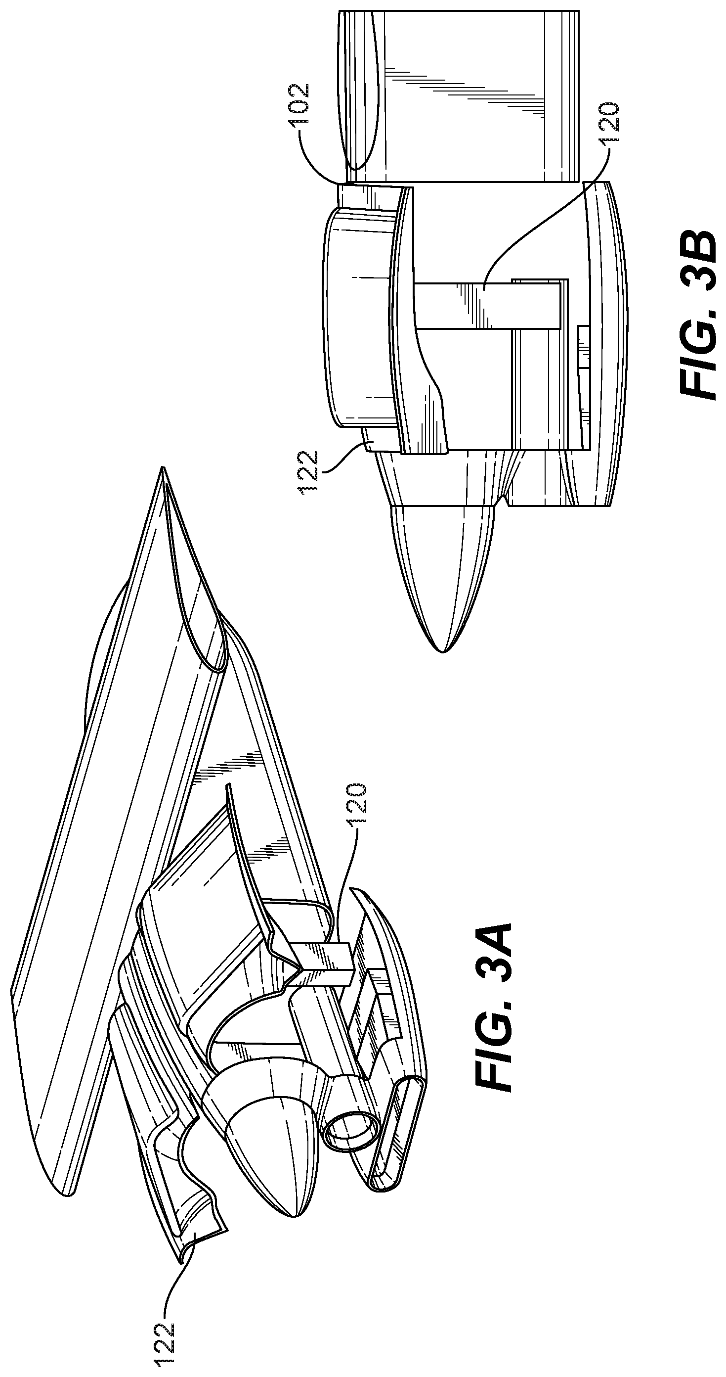
[0026] As seen in FIGS. 3a and 3b, the glycol/air heat exchangers 120 can be secured in place and not move along with the cowl doors 122, when the cowl doors 122 are opened for maintenance. It is also considered, As seen in FIG. 3c, the side heat exchangers can be attached to each of the nacelle cowls, which can be hingedly attached to the nacelle body 102, wherein the nacelle access doors allow for drip testing when placed in the open position. The cowls can swing open such that the engine or engines are exposed to the ground with allowing any fluids excreted by the engine or engines to reach the ground.
[0027] Referring to FIGS. 4a- and 4b, a cooling system for a nacelle of an aircraft of a having hybrid-electric propulsion system can include a nacelle body 102 including a bottom cooling air intake 410 disposed below a propeller hub 405 for supplying air to an oil-air cooler, wherein the bottom cooling air intake includes a horizontal splitter 412 dividing the bottom cooling air intake into a first channel and a second channel. As seen in FIGS. 4a and 4b the horizontal splitter 412 forms two separate channels, with the first channel 490 leading to a first heat exchanger 492, and the second channel 491 leading to a second heat exchanger 493, where the first heat exchanger 492 is an air-oil heat exchanger, and the second heat exchanger 493 is a glycol air heat exchanger.
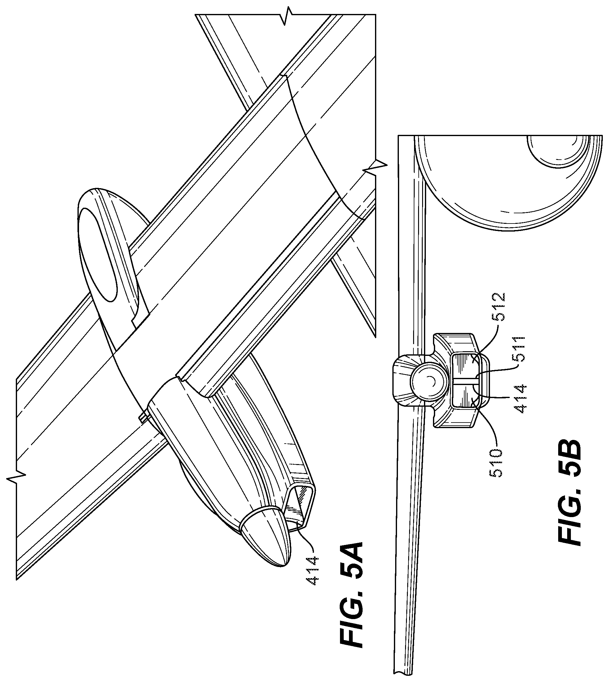
[0028] As seen in FIGS. 5a and 5, a vertical splitter 414 can form three separate channels which lead to different air intakes and different heat exchangers. The splitter can form three separate channels 510, 511, and 512, with the first channel 510 leading to a first heat exchanger, the second channel 511 leading to a second heat exchanger, and a third channel 512 leading to a turbine compressor assembly, wherein the first heat exchanger 492 is an air-oil heat exchanger, and the second heat exchanger 493 is a glycol air heat exchanger.
[0029] It is further envisioned that the heat motor of the system described above could be a heat engine of any type, e.g., a gas turbine, spark ignited, diesel, rotary or reciprocating engine of any fuel type and with any configuration of turbomachiney elements, either turbocharger, turbo supercharger, supercharger and exhaust recovery turbo compounding, either mechanically, electrically, hydraulically or pneumatically driven. An example of a rotary engine suitable for this application is disclosed in U.S. Pat. No. 10,145,291, the disclosure of which is herein incorporated by reference in its entirety.
[0030] The methods and systems of the present disclosure, as described above and shown in the drawings, provide for electrical power system with superior properties including increased reliability and stability, and reduced size, weight, complexity, and/or cost. While the apparatus and methods of the subject disclosure have been showing and described with reference to embodiments, those skilled in the art will readily appreciate that changes and/or modifications may be made thereto without departing from the spirit and score of the subject disclosure.
* * * * *
D00000
D00001
D00002
D00003
D00004
D00005
D00006
D00007
D00008
XML
uspto.report is an independent third-party trademark research tool that is not affiliated, endorsed, or sponsored by the United States Patent and Trademark Office (USPTO) or any other governmental organization. The information provided by uspto.report is based on publicly available data at the time of writing and is intended for informational purposes only.
While we strive to provide accurate and up-to-date information, we do not guarantee the accuracy, completeness, reliability, or suitability of the information displayed on this site. The use of this site is at your own risk. Any reliance you place on such information is therefore strictly at your own risk.
All official trademark data, including owner information, should be verified by visiting the official USPTO website at www.uspto.gov. This site is not intended to replace professional legal advice and should not be used as a substitute for consulting with a legal professional who is knowledgeable about trademark law.