Track System For Traction Of A Vehicle
THOMPSON; Ronald H. ; et al.
U.S. patent application number 16/063102 was filed with the patent office on 2020-09-03 for track system for traction of a vehicle. The applicant listed for this patent is Ronald H. THOMPSON, Jereme ZUCHOSKI. Invention is credited to Ronald H. THOMPSON, Jereme ZUCHOSKI.
| Application Number | 20200277012 16/063102 |
| Document ID | / |
| Family ID | 1000004855448 |
| Filed Date | 2020-09-03 |


View All Diagrams
| United States Patent Application | 20200277012 |
| Kind Code | A1 |
| THOMPSON; Ronald H. ; et al. | September 3, 2020 |
TRACK SYSTEM FOR TRACTION OF A VEHICLE
Abstract
A track system for traction of a vehicle (e.g., an all-terrain vehicle (ATV), an agricultural vehicle, etc.) may be designed (e.g., may comprise non-pneumatic tires) to enhance its use or performance and/or that of the vehicle such as, for example, by being lightweight and/or by better handling loads, including, for instance, those resulting from track tension within the track system and/or from unevenness or other aspects of the ground, including encounters (e.g., impacts) with obstacles on the ground (e.g., rocks, portions of trees, debris, bumps, abrupt changes in ground level, etc.). The track system may comprise tension-based non-pneumatic tires.
| Inventors: | THOMPSON; Ronald H.; (Greenville, SC) ; ZUCHOSKI; Jereme; (Sherbrooke, CA) | ||||||||||
| Applicant: |
|
||||||||||
|---|---|---|---|---|---|---|---|---|---|---|---|
| Family ID: | 1000004855448 | ||||||||||
| Appl. No.: | 16/063102 | ||||||||||
| Filed: | December 16, 2016 | ||||||||||
| PCT Filed: | December 16, 2016 | ||||||||||
| PCT NO: | PCT/US2016/067327 | ||||||||||
| 371 Date: | June 15, 2018 |
Related U.S. Patent Documents
| Application Number | Filing Date | Patent Number | ||
|---|---|---|---|---|
| 62268309 | Dec 16, 2015 | |||
| Current U.S. Class: | 1/1 |
| Current CPC Class: | B62D 55/26 20130101; B62D 55/202 20130101; B62D 55/305 20130101 |
| International Class: | B62D 55/30 20060101 B62D055/30; B62D 55/20 20060101 B62D055/20; B62D 55/26 20060101 B62D055/26 |
Claims
1. A track system for traction of a vehicle, the track system comprising: a) a track for engaging the ground; and b) a track-engaging assembly for driving and guiding the track around the track-engaging assembly, the track-engaging assembly comprising: i. a drive wheel for driving the track; and ii. an idler wheel contacting a bottom run of the track, the idler wheel comprising a non-pneumatic tire, the non-pneumatic tire comprising: an annular beam configured to deflect at an area of contact of the non-pneumatic tire with the track; and an annular support disposed radially inwardly of the annular beam and configured to resiliently deform under loading on the idler wheel for supporting the loading on the idler wheel by tension.
2. The track system of claim 1, wherein the annular support is resiliently deformable such that a portion of the annular support between an axis of rotation of the idler wheel and the area of contact of the idler wheel with the track is compressed and a portion of the annular support between the axis of rotation of the idler wheel and a peripheral part of the idler wheel not in contact with the track is in tension.
3. The wheel of claim 1, wherein the annular support comprises a plurality of spokes.
4. The track system of claim 3, wherein the spokes are resiliently deformable such that respective ones of the spokes between an axis of rotation of the idler wheel and the area of contact of the idler wheel with the track are compressed and respective ones of the spokes between the axis of rotation of the idler wheel and a peripheral part of the idler wheel not in contact with the track are in tension.
5. The track system of claim 1, wherein each of the spokes is curved.
6. The track system of claim 1, wherein the annular beam is configured to deflect more by shearing than by bending when the idler wheel encounters an obstacle on the ground.
7. The track system of claim 1, wherein the annular beam is configured to deflect more by shearing than by bending when loaded against a flat surface to a contact length of at least 40% of a diameter of the idler wheel.
8. The track system of claim 7, wherein a ratio of a transverse deflection of the annular beam due to shear over a transverse deflection of the annular beam due to bending at a center of the area of contact of the non-pneumatic tire with the track is at least 2 when the idler wheel is loaded against the flat surface to the contact length of at least 40% of the diameter of the idler wheel.
9. The track system of claim 7, wherein a ratio of a transverse deflection of the annular beam due to shear over a transverse deflection of the annular beam due to bending at a center of the area of contact of the non-pneumatic tire with the track is at least 3 when the idler wheel is loaded against the flat surface to the contact length of at least 40% of the diameter of the idler wheel.
10. The track system of claim 7, wherein a ratio of a transverse deflection of the annular beam due to shear over a transverse deflection of the annular beam due to bending at a center of the area of contact of the non-pneumatic tire with the track is at least 5 when the idler wheel is loaded against the flat surface to the contact length of at least 40% of the diameter of the idler wheel.
11. The track system of claim 7, wherein a ratio of a transverse deflection of the annular beam due to shear over a transverse deflection of the annular beam due to bending at a center of the area of contact of the non-pneumatic tire with the track is at least 7 when the idler wheel is loaded against the flat surface to the contact length of at least 40% of the diameter of the idler wheel.
12. The track system of claim 1, wherein the annular beam comprises a plurality of openings distributed in a circumferential direction of the non-pneumatic tire.
13. The track system of claim 12, wherein each of the openings extends from a first lateral side of the non-pneumatic tire to a second lateral side of the non-pneumatic tire.
14. The track system of claim 1, wherein the non-pneumatic tire comprises a tread.
15. The track system of claim 14, wherein the annular beam comprises a first elastomeric material and the tread comprises a second elastomeric material different from the first elastomeric material.
16. The track system of claim 1, wherein a ratio of a width of the non-pneumatic tire over a width of the track is at least 0.2.
17. The track system of claim 1, wherein a ratio of a width of the non-pneumatic tire over a width of the track is at least 0.3.
18. The track system of claim 1, wherein a ratio of a width of the non-pneumatic tire over a width of the track is at least 0.4.
19. The track system of claim 1, wherein the idler wheel is a first idler wheel, the track-engaging assembly comprises a second idler wheel contacting the bottom run of the track and spaced from the first idler wheel in a widthwise direction of the track system, the second idler wheel comprising a non-pneumatic tire, the non-pneumatic tire of the second idler wheel comprising: an annular beam configured to deflect at an area of contact of the non-pneumatic tire of the second idler wheel with the track; and an annular support disposed radially inwardly of the annular beam of the second idler wheel and configured to resiliently deform under loading on the second idler wheel for supporting the loading on the second idler wheel by tension.
20. The track system of claim 19, wherein a sum of a width of the non-pneumatic tire of the first idler wheel and a width of the non-pneumatic tire of the second idler wheel corresponds to at least a majority of a width of the track.
21. The track system of claim 20, wherein the sum of the width of the non-pneumatic tire of the first idler wheel and the width of the non-pneumatic tire of the second idler wheel corresponds to at least 60% of the width of the track.
22. The track system of claim 20, wherein the sum of the width of the non-pneumatic tire of the first idler wheel and the width of the non-pneumatic tire of the second idler wheel corresponds to at least 80% of the width of the track.
23. The track system of claim 1, wherein a ratio of a mass of the idler wheel over an outer diameter of the idler wheel normalized by a width of the idler wheel is no more than 0.0005 kg/mm.sup.2.
24. The track system of claim 23, wherein the ratio of the mass of the idler wheel over the outer diameter of the idler wheel normalized by the width of the idler wheel is no more than 0.0004 kg/mm.sup.2.
25. The track system of claim 23, wherein the ratio of the mass of the idler wheel over the outer diameter of the idler wheel normalized by the width of the idler wheel is no more than 0.0003 kg/mm.sup.2.
26. The track system of claim 23, wherein the ratio of the mass of the idler wheel over the outer diameter of the idler wheel normalized by the width of the idler wheel is no more than 0.0002 kg/mm.sup.2.
27. The track system of claim 23, wherein the ratio of the mass of the idler wheel over the outer diameter of the idler wheel normalized by the width of the idler wheel is no more than 0.00015 kg/mm.sup.2.
28. The track system of claim 1, wherein a ratio of a radial stiffness of the idler wheel over the outer diameter of the idler wheel normalized by the width of the idler wheel is between 0.0001 kgf/mm.sup.3 and 0.0002 kgf/mm.sup.3.
29. The track system of claim 1, wherein a radial stiffness of the idler wheel is no more than 15 kgf/mm.
30. The track system of claim 1, wherein a radial stiffness of the idler wheel is no more than 11 kgf/mm.
31. The track system of claim 1, wherein a radial stiffness of the idler wheel is no more than 8 kgf/mm.
32. The track system of claim 1, wherein: the annular support comprises a plurality of spokes extending from the annular beam to a hub of the idler wheel; and a ratio of a volume occupied by the spokes over a volume bounded by the annular beam and the hub of the idler wheel is no more than 15%.
33. The track system of claim 1, wherein: the annular support comprises a plurality of spokes extending from the annular beam to a hub of the idler wheel; and a ratio of a volume occupied by the spokes over a volume bounded by the annular beam and the hub of the idler wheel is no more than 10%.
34. The track system of claim 1, wherein: the annular support comprises a plurality of spokes extending from the annular beam to a hub of the idler wheel; and a ratio of a volume occupied by the spokes over a volume bounded by the annular beam and the hub of the idler wheel is no more than 6%.
35. The track system of claim 1, wherein idler wheel comprises a hub comprising a central member and a plurality of arms projecting radially outwardly from the central member.
36. The track system of claim 1, wherein: a sectional height of the non-pneumatic tire is half of a difference between an outer diameter and an inner diameter of the non-pneumatic tire; and a ratio of the sectional height of the non-pneumatic tire over a width of the non-pneumatic tire is at least 70%.
37. The track system of claim 1, wherein: a sectional height of the non-pneumatic tire is half of a difference between an outer diameter and an inner diameter of the non-pneumatic tire; and a ratio of the sectional height of the non-pneumatic tire over a width of the non-pneumatic tire is at least 90%.
38. The track system of claim 1, wherein: a sectional height of the non-pneumatic tire is half of a difference between an outer diameter and an inner diameter of the non-pneumatic tire; and a ratio of the sectional height of the non-pneumatic tire over a width of the non-pneumatic tire is at least 110%.
39. The track system of claim 1, wherein an inner diameter of the non-pneumatic tire is no more than half of an outer diameter of the non-pneumatic tire.
40. The track system of claim 39, wherein the inner diameter of the non-pneumatic tire is less than half of the outer diameter of the non-pneumatic tire.
41. The track system of claim 40, wherein the inner diameter of the non-pneumatic tire is no more than 40% of the outer diameter of the non-pneumatic tire.
42. The track system of claim 1, wherein the idler wheel is a first idler wheel, the track-engaging assembly comprises a second idler wheel contacting the bottom run of the track and spaced from the first idler wheel in a longitudinal direction of the track system, and an axis of rotation of the drive wheel is located between an axis of rotation of the first idler wheel and an axis of rotation of the second idler wheel in the longitudinal direction of the track system.
43. The track system of claim 42, wherein the first idler wheel is a leading idler wheel and the second idler wheel is a trailing idler wheel.
44. The track system of claim 42, wherein the second idler wheel comprises a non-pneumatic tire, the non-pneumatic tire of the second idler wheel comprising: an annular beam configured to deflect at an area of contact of the non-pneumatic tire of the second idler wheel with the track; and an annular support disposed radially inwardly of the annular beam of the second idler wheel and configured to resiliently deform under loading on the second idler wheel for supporting the loading on the second idler wheel by tension.
45. The track system of claim 42, wherein the axis of rotation of the first idler wheel is movable relative to the axis of rotation of the drive wheel when the track system moves on the ground.
46. The track system of claim 42, wherein the track-engaging assembly comprises a plurality of roller wheels contacting the bottom run of the track and disposed between the first idler wheel and the second idler wheel in the longitudinal direction of the track system.
47. The track system of claim 46, wherein the first idler wheel is larger in diameter than a given one of the roller wheels.
48. The track system of claim 47, wherein the first idler wheel is wider than the given one of the roller wheels in a widthwise direction of the track system.
49. The track system of claim 1, wherein the track comprises an inner surface and a plurality of wheel-contacting projections from the inner surface for contacting at least one of the drive wheel and the idler wheel, and a width of the idler wheel in a widthwise direction of the track system is greater than a dimension of a given one of the wheel-contacting projections in the widthwise direction of the track system.
50. The track system of claim 49, wherein the plurality of wheel-contacting projections comprises a plurality of drive projections and the drive wheel comprises a sprocket for engaging the drive projections.
51. The track system of claim 42, wherein the track-engaging assembly comprises a frame supporting the first idler wheel and the second idler wheel and movable relative to the axis of rotation of the drive wheel.
52. The track system of claim 51, wherein the frame is pivotable relative to the axis of rotation of the drive wheel.
53. The track system of claim 52, wherein a pivot axis of the frame is located between the first idler wheel and the second idler wheel in the longitudinal direction of the track system.
54. The track system of claim 53, wherein the pivot axis of the frame corresponds to the axis of rotation of the drive wheel.
55. The track system of claim 42, wherein a distance between the axis of rotation of the drive wheel and the axis of rotation of the first idler wheel in the longitudinal direction of the track system is different from a distance between the axis of rotation of the drive wheel and the axis of rotation of the second idler wheel in the longitudinal direction of the track system.
56. The track system of claim 1, wherein the track comprises a plurality of drive projections and the drive wheel comprises a sprocket for engaging the drive projections.
57. The track system of claim 42, wherein the bottom run of the track rises towards the first idler wheel.
58. The track system of claim 57, wherein the bottom run of the track rises towards the second idler wheel.
59. The track system of claim 6, wherein the annular beam comprises a reinforcing layer running in a circumferential direction of the non-pneumatic tire, and the reinforcing layer is unnecessary for the annular beam to deflect more by shearing than by bending at the area of contact of the non-pneumatic tire with the track.
60. The track system of claim 6, wherein the annular beam comprises a reinforcing layer running in a circumferential direction of the non-pneumatic tire and is free of any equivalent reinforcing layer running in the circumferential direction of the non-pneumatic tire and spaced from the reinforcing layer in a radial direction of the non-pneumatic tire.
61. The track system of claim 6, wherein the annular beam comprises a reinforcing layer running in a circumferential direction of the non-pneumatic tire and is free of any substantially inextensible reinforcing layer running in the circumferential direction of the non-pneumatic tire and spaced from the reinforcing layer in a radial direction of the non-pneumatic tire.
62. The track system of claim 6, wherein the annular beam comprises a reinforcing layer running in a circumferential direction of the non-pneumatic tire, the reinforcing layer is located between a neutral axis of the annular beam and a given one of an inner peripheral extent and an outer peripheral extent of the annular beam in a radial direction of the non-pneumatic tire, and the annular beam is free of any substantially inextensible reinforcing layer running in the circumferential direction of the non-pneumatic tire between the neutral axis of the annular beam and the other one of the inner peripheral extent and the outer peripheral extent of the annular beam in the radial direction of the non-pneumatic tire.
63. The track system of claim 62, wherein the reinforcing layer is disposed radially inwardly of the neutral axis of the annular beam, and the annular beam is free of any substantially inextensible reinforcing layer running in the circumferential direction of the non-pneumatic tire radially outwardly of the neutral axis of the annular beam.
64. The track system of claim 6, wherein the annular beam comprises a plurality of openings distributed in a circumferential direction of the non-pneumatic tire, the annular beam comprises a reinforcing layer running in the circumferential direction of the non-pneumatic tire, the reinforcing layer is disposed between an inner peripheral extent of the annular beam and the openings in a radial direction of the non-pneumatic tire, and the annular beam is free of any substantially inextensible reinforcing layer running in the circumferential direction of the non-pneumatic tire between an outer peripheral extent of the annular beam and the openings in the radial direction of the non-pneumatic tire.
65. The track system of claim 59, wherein the reinforcing layer comprises reinforcing cables extending generally parallel to one another in the circumferential direction of the non-pneumatic tire.
66. The track system of claim 65, wherein the reinforcing layer comprises transversal elongate elements extending transversally to and interconnecting the reinforcing cables.
67. The track system of claim 59, wherein the reinforcing layer comprises reinforcing fabric.
68. The track system of claim 1, wherein the track system is steerable by a steering mechanism of the vehicle to change an orientation of the track system relative to the vehicle.
69. A set of track systems for traction of a vehicle, wherein each of at least two of the track systems is as claimed in claim 1.
70. A vehicle comprising the track system of claim 1.
71. The vehicle of claim 70, wherein the vehicle is an all-terrain vehicle (ATV).
72. A track system for traction of a vehicle, the track system comprising: a) a track for engaging the ground; and b) a track-engaging assembly for driving and guiding the track around the track-engaging assembly, the track-engaging assembly comprising: i. a drive wheel for driving the track; and ii. an idler wheel contacting a bottom run of the track, the idler wheel comprising a non-pneumatic tire, the non-pneumatic tire comprising: an annular beam configured to deflect at an area of contact of the non-pneumatic tire with the track, the annular beam being configured to deflect more by shearing than by bending at the area of contact of the non-pneumatic tire with the track when the idler wheel encounters an obstacle on the ground; and an annular support disposed radially inwardly of the annular beam and configured to resiliently deform under loading on the idler wheel.
73. A track system for traction of a vehicle, the track system comprising: a) a track for engaging the ground; and b) a track-engaging assembly for driving and guiding the track around the track-engaging assembly, the track-engaging assembly comprising: i. a drive wheel for driving the track; and ii. an idler wheel contacting a bottom run of the track, the idler wheel comprising a non-pneumatic tire, the non-pneumatic tire comprising: an annular beam configured to deflect at an area of contact of the non-pneumatic tire with the track, the annular beam comprising a plurality of openings distributed in a circumferential direction of the non-pneumatic tire, each of the openings extending from a first lateral side of the non-pneumatic tire to a second lateral side of the non-pneumatic tire; and an annular support disposed radially inwardly of the annular beam and configured to resiliently deform under loading on the idler wheel.
74. A track system for traction of a vehicle, the track system comprising: a) a track for engaging the ground; and b) a track-engaging assembly for driving and guiding the track around the track-engaging assembly, the track-engaging assembly comprising: i. a drive wheel for driving the track; and ii. an idler wheel contacting a bottom run of the track, a radial stiffness of the idler wheel being different under different types of loading on the idler wheel.
75. The track system of claim 74, wherein a first one of the different types of loading on the idler wheel occurs when the track system is operated at lower speed and higher torque than when a second one of the different types of loading on the idler wheel occurs, and the radial stiffness of the idler wheel is greater under the first one of the different types of loading on the idler wheel than under the second one of the different types of loading on the idler wheel.
76. The track system of claim 75, wherein the first one of the different types of loading on the idler wheel is associated with greater tension of the track than the second one of the different types of loading on the idler wheel.
77. The track system of claim 75, wherein the second one of the different types of loading on the idler wheel is associated with an impact on the track system.
78. The track system of claim 75, wherein a ratio of the radial stiffness of the idler wheel under the first one of the different types of loading on the idler wheel over the radial stiffness of the idler wheel under the second one of the different types of loading on the idler wheel is at least 2.
79. The track system of claim 75, wherein a ratio of the radial stiffness of the idler wheel under the first one of the different types of loading on the idler wheel over the radial stiffness of the idler wheel under the second one of the different types of loading on the idler wheel is at least 3.
80. The track system of claim 75, wherein a ratio of the radial stiffness of the idler wheel under the first one of the different types of loading on the idler wheel over the radial stiffness of the idler wheel under the second one of the different types of loading on the idler wheel is at least 4.
81. The track system of claim 75, wherein a ratio of the radial stiffness of the idler wheel under the first one of the different types of loading on the idler wheel over the radial stiffness of the idler wheel under the second one of the different types of loading on the idler wheel is at least 5.
82. The track system of claim 74, wherein the idler wheel comprises a non-pneumatic tire.
83. The track system of claim 82, wherein the non-pneumatic tire comprises: an annular beam configured to deflect at an area of contact of the non-pneumatic tire with the track; and an annular support disposed radially inwardly of the annular beam and configured to resiliently deform under the different types of loading on the idler wheel.
84. The track system of claim 83, wherein the annular beam comprises a plurality of openings distributed in a circumferential direction of the non-pneumatic tire.
85. The track system of claim 83, wherein the annular support comprises a plurality of spokes.
86. A set of track systems for traction of a vehicle, wherein each of at least two of the track systems is as claimed in claim 74.
87. A vehicle comprising the track system of claim 74.
88. The vehicle of claim 87, wherein the vehicle is an all-terrain vehicle (ATV).
89. A track system for traction of a vehicle, the track system comprising: a) a track for engaging the ground; and b) a track-engaging assembly for driving and guiding the track around the track-engaging assembly, the track-engaging assembly comprising: i. a drive wheel for driving the track; ii. a leading idler wheel and a trailing idler wheel that contact a bottom run of the track, an axis of rotation of the drive wheel being located between an axis of rotation of the leading idler wheel and an axis of rotation of the trailing idler wheel in a longitudinal direction of the track system, the leading idler wheel being structurally different from the trailing idler wheel.
90. The track system of claim 89, wherein a material of the leading idler wheel is different from a material of the trailing idler wheel.
91. The track system of claim 89, wherein a shape of the leading idler wheel is different from a shape of the trailing idler wheel.
92. The track system of claim 89, wherein a radial stiffness of the leading idler wheel is different from a radial stiffness of the trailing idler wheel.
93. The track system of claim 92, wherein the radial stiffness of the leading idler wheel is less than the radial stiffness of the trailing idler wheel.
94. The track system of claim 93, wherein a ratio of the radial stiffness of the leading idler wheel over the radial stiffness of the trailing idler wheel is no more than 0.9.
95. The track system of claim 93, wherein a ratio of the radial stiffness of the leading idler wheel over the radial stiffness of the trailing idler wheel is no more than 0.7.
96. The track system of claim 93, wherein a ratio of the radial stiffness of the leading idler wheel over the radial stiffness of the trailing idler wheel is no more than 0.5.
97. The track system of claim 90, wherein a modulus of elasticity of the material of the leading idler wheel is different from a modulus of elasticity of the material of the trailing idler wheel.
98. The track system of claim 97, wherein the modulus of elasticity of the material of the leading idler wheel is less than the modulus of elasticity of the material of the trailing idler wheel.
99. The track system of claim 98, wherein a ratio of the modulus of elasticity of the material of the leading idler wheel over the modulus of elasticity of the material of the trailing idler wheel is no more than 0.9.
100. The track system of claim 98, wherein a ratio of the modulus of elasticity of the material of the leading idler wheel over the modulus of elasticity of the material of the trailing idler wheel is no more than 0.7.
101. The track system of claim 98, wherein a ratio of the modulus of elasticity of the material of the leading idler wheel over the modulus of elasticity of the material of the trailing idler wheel is no more than 0.5.
102. The track system of claim 89, wherein each of the leading idler wheel and the trailing idler wheel comprises a non-pneumatic tire.
103. The track system of claim 102, wherein the non-pneumatic tire of each idler wheel of the leading idler wheel and the trailing idler wheel comprises: an annular beam configured to deflect at an area of contact of the non-pneumatic tire with the track; and an annular support disposed radially inwardly of the annular beam and configured to resiliently deform under loading on the idler wheel.
104. The track system of claim 103, wherein the annular beam comprises a plurality of openings distributed in a circumferential direction of the non-pneumatic tire.
105. The track system of claim 103, wherein the annular support comprises a plurality of spokes.
106. The track system of claim 102, wherein a shape of the non-pneumatic tire of the leading idler wheel is different from a shape of the non-pneumatic tire of the trailing idler wheel.
107. The track system of claim 103, wherein a shape of the annular beam of the non-pneumatic tire of the leading idler wheel is different from a shape of the annular beam of the non-pneumatic tire of the trailing idler wheel.
108. The track system of claim 107, wherein the annular beam comprises a plurality of openings distributed in a circumferential direction of the non-pneumatic tire, and a number of the openings of the annular beam of the non-pneumatic tire of the leading idler wheel is different from a number of the openings of the annular beam of the non-pneumatic tire of the trailing idler wheel.
109. The track system of claim 108, wherein the number of the openings of the annular beam of the non-pneumatic tire of the leading idler wheel is greater than the number of the openings of the annular beam of the non-pneumatic tire of the trailing idler wheel.
110. The track system of claim 107, wherein the annular beam comprises a plurality of openings distributed in a circumferential direction of the non-pneumatic tire, and a configuration of the openings of the annular beam of the non-pneumatic tire of the leading idler wheel is different from a configuration of the openings of the annular beam of the non-pneumatic tire of the trailing idler wheel.
111. The track system of claim 110, wherein a size of the openings of the annular beam of the non-pneumatic tire of the leading idler wheel is greater than a size of the openings of the annular beam of the non-pneumatic tire of the trailing idler wheel.
112. The track system of claim 103, wherein a shape of the annular support of the non-pneumatic tire of the leading idler wheel is different from a shape of the annular support of the non-pneumatic tire of the trailing idler wheel.
113. The track system of claim 112, wherein the annular support comprises a plurality of spokes distributed in a circumferential direction of the non-pneumatic tire, and a number of the spokes of the annular support of the non-pneumatic tire of the leading idler wheel is different from a number of the spokes of the annular support of the non-pneumatic tire of the trailing idler wheel.
114. The track system of claim 113, wherein the number of the spokes of the annular support of the non-pneumatic tire of the leading idler wheel is less than the number of the spokes of the annular support of the non-pneumatic tire of the trailing idler wheel.
115. The track system of claim 112, wherein the annular support comprises a plurality of spokes distributed in a circumferential direction of the non-pneumatic tire, and a configuration of the spokes of the annular support of the non-pneumatic tire of the leading idler wheel is different from a configuration of the spokes of the annular support of the non-pneumatic tire of the trailing idler wheel.
116. The track system of claim 115, wherein a size of the spokes of the annular support of the non-pneumatic tire of the leading idler wheel is less than a size of the spokes of the annular support of the non-pneumatic tire of the trailing idler wheel.
117. A set of track systems for traction of a vehicle, wherein each of at least two of the track systems is as claimed in claim 89.
118. A vehicle comprising the track system of claim 89.
119. The vehicle of claim 118, wherein the vehicle is an all-terrain vehicle (ATV).
Description
CROSS-REFERENCE TO RELATED APPLICATION
[0001] This application claims priority from U.S. Provisional Patent Application 62/268,309 filed on Dec. 16, 2015 and hereby incorporated by reference herein.
FIELD
[0002] The invention relates generally to track systems for tractions of vehicles, such as all-terrain vehicles (ATVs) and other off-road vehicles.
BACKGROUND
[0003] Certain vehicles, such as all-terrain vehicles (ATVs), agricultural vehicles (e.g., tractors, harvesters, etc.), may be equipped with track systems which enhance their traction and floatation on soft, slippery and/or irregular grounds (e.g., soil, mud, sand, ice, snow, etc.) on which they operate. A track system comprises a track disposed around a track-engaging assembly including a frame and track-contacting wheels that drive and guide the track around the track-engaging assembly.
[0004] As they travel on the ground, tracked vehicles can encounter various obstacles (e.g., rocks, portions of trees, debris, ice blocks, bumps or other abrupt changes in ground level, etc.) depending on their environment. Such obstacles can create shocks in their track systems. Depending on their intensity, these shocks may affect ride quality and/or structural integrity of the track systems. Also, some obstacles may sometimes prove more difficult to overcome. This can negatively impact a tracked vehicle's performance by slowing it down or in some cases bringing it to a standstill.
[0005] In some cases, shock absorption of track systems may be enhanced by providing some resilience within the track systems (e.g., wheels or other components that are less stiff). However, this may cause issues in view of track tensioning.
[0006] For these and other reasons, there is a need to improve track systems for traction of vehicles.
SUMMARY
[0007] According to various aspects of the invention, there is provided a track system for traction of a vehicle. The track system may be designed (e.g., may comprise non-pneumatic tires) to enhance its use or performance and/or that of the vehicle such as, for example, by being lightweight and/or by better handling loads, including, for instance, those resulting from track tension within the track system and/or from unevenness or other aspects of the ground, including encounters (e.g., impacts) with obstacles on the ground (e.g., rocks, portions of trees, debris, bumps, abrupt changes in ground level, etc.). For instance, in some embodiments, the track system may comprise tension-based non-pneumatic tires.
[0008] For example, according to an aspect of the invention, there is provided a track system for traction of a vehicle. The track system comprises: a track for engaging the ground; and a track-engaging assembly for driving and guiding the track around the track-engaging assembly. The track-engaging assembly comprises: a drive wheel for driving the track; and an idler wheel contacting a bottom run of the track. The idler wheel comprises a non-pneumatic tire. The non-pneumatic tire comprises: an annular beam configured to deflect at an area of contact of the non-pneumatic tire with the track; and an annular support disposed radially inwardly of the annular beam and configured to resiliently deform under loading on the idler wheel for supporting the loading on the idler wheel by tension.
[0009] According to an aspect of the invention, there is provided a track system for traction of a vehicle. The track system comprises: a track for engaging the ground; and a track-engaging assembly for driving and guiding the track around the track-engaging assembly. The track-engaging assembly comprises: a drive wheel for driving the track; and an idler wheel contacting a bottom run of the track. The idler wheel comprises a non-pneumatic tire. The non-pneumatic tire comprises an annular beam configured to deflect at an area of contact of the non-pneumatic tire with the track. The annular beam is configured to deflect more by shearing than by bending at the area of contact of the non-pneumatic tire with the track when the idler wheel encounters an obstacle on the ground. The non-pneumatic tire comprises an annular support disposed radially inwardly of the annular beam and configured to resiliently deform under loading on the idler wheel.
[0010] According to an aspect of the invention, there is provided a track system for traction of a vehicle. The track system comprises: a track for engaging the ground; and a track-engaging assembly for driving and guiding the track around the track-engaging assembly. The track-engaging assembly comprises: a drive wheel for driving the track; and an idler wheel contacting a bottom run of the track. The idler wheel comprises a non-pneumatic tire. The non-pneumatic tire comprises an annular beam configured to deflect at an area of contact of the non-pneumatic tire with the track. The annular beam is configured to deflect more by shearing than by bending at the area of contact of the non-pneumatic tire with the track when the idler wheel is loaded against a flat surface to a contact length of at least 40% of a diameter of the idler wheel. The non-pneumatic tire comprises an annular support disposed radially inwardly of the annular beam and configured to resiliently deform under loading on the idler wheel.
[0011] According to an aspect of the invention, there is provided a track system for traction of a vehicle. The track system comprises: a track for engaging the ground; and a track-engaging assembly for driving and guiding the track around the track-engaging assembly. The track-engaging assembly comprises: a drive wheel for driving the track; and an idler wheel contacting a bottom run of the track. The idler wheel comprises a non-pneumatic tire. The non-pneumatic tire comprises an annular beam configured to deflect at an area of contact of the non-pneumatic tire with the track. The annular beam comprises a plurality of openings distributed in a circumferential direction of the non-pneumatic tire. Each of the openings extends from a first lateral side of the non-pneumatic tire to a second lateral side of the non-pneumatic tire. The non-pneumatic tire comprises an annular support disposed radially inwardly of the annular beam and configured to resiliently deform under loading on the idler wheel.
[0012] According to an aspect of the invention, there is provided a track system for traction of a vehicle. The track system comprises: a track for engaging the ground; and a track-engaging assembly for driving and guiding the track around the track-engaging assembly. The track-engaging assembly comprises: a drive wheel for driving the track; and an idler wheel contacting a bottom run of the track. A radial stiffness of the idler wheel is different under different types of loading on the idler wheel.
[0013] According to an aspect of the invention, there is provided a track system for traction of a vehicle. The track system comprises: a track for engaging the ground; and a track-engaging assembly for driving and guiding the track around the track-engaging assembly. The track-engaging assembly comprises: a drive wheel for driving the track; and a leading idler wheel and a trailing idler wheel that contact a bottom run of the track. An axis of rotation of the drive wheel is located between an axis of rotation of the leading idler wheel and an axis of rotation of the trailing idler wheel in a longitudinal direction of the track system. The leading idler wheel is structurally different from the trailing idler wheel.
[0014] These and other aspects of the invention will now become apparent to those of ordinary skill in the art upon review of the following description of embodiments in conjunction with the accompanying drawings.
BRIEF DESCRIPTION OF THE DRAWINGS
[0015] A detailed description of embodiments is provided below, by way of example only, with reference to the accompanying drawings, in which:
[0016] FIGS. 1A and 1B show an example of an all-terrain vehicle (ATV) comprising track systems in accordance with an embodiment of the invention;
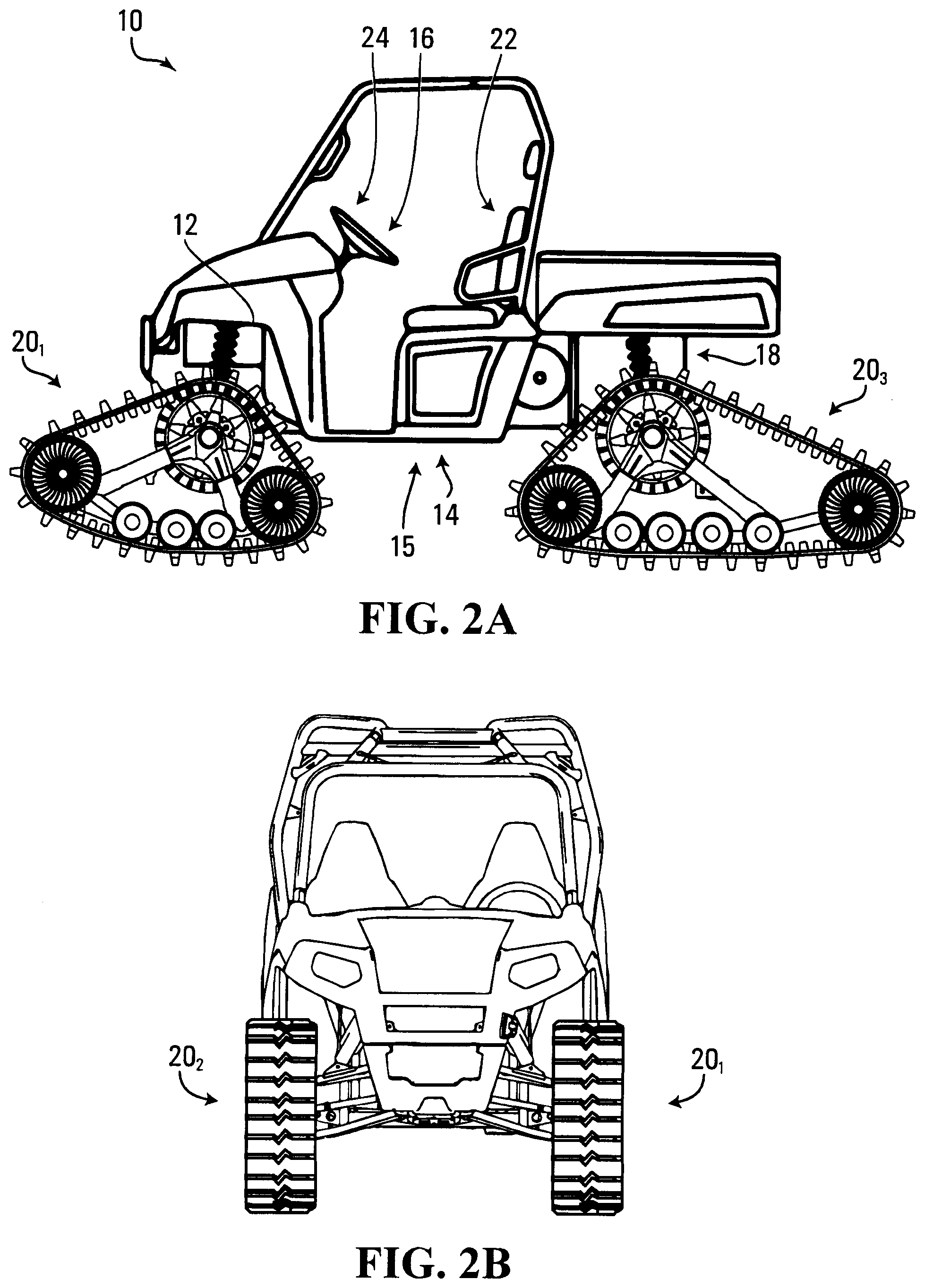
[0017] FIGS. 2A and 2B show another example in which the ATV is a utility terrain or utility task vehicle (UTV) in accordance with another embodiment of the invention;
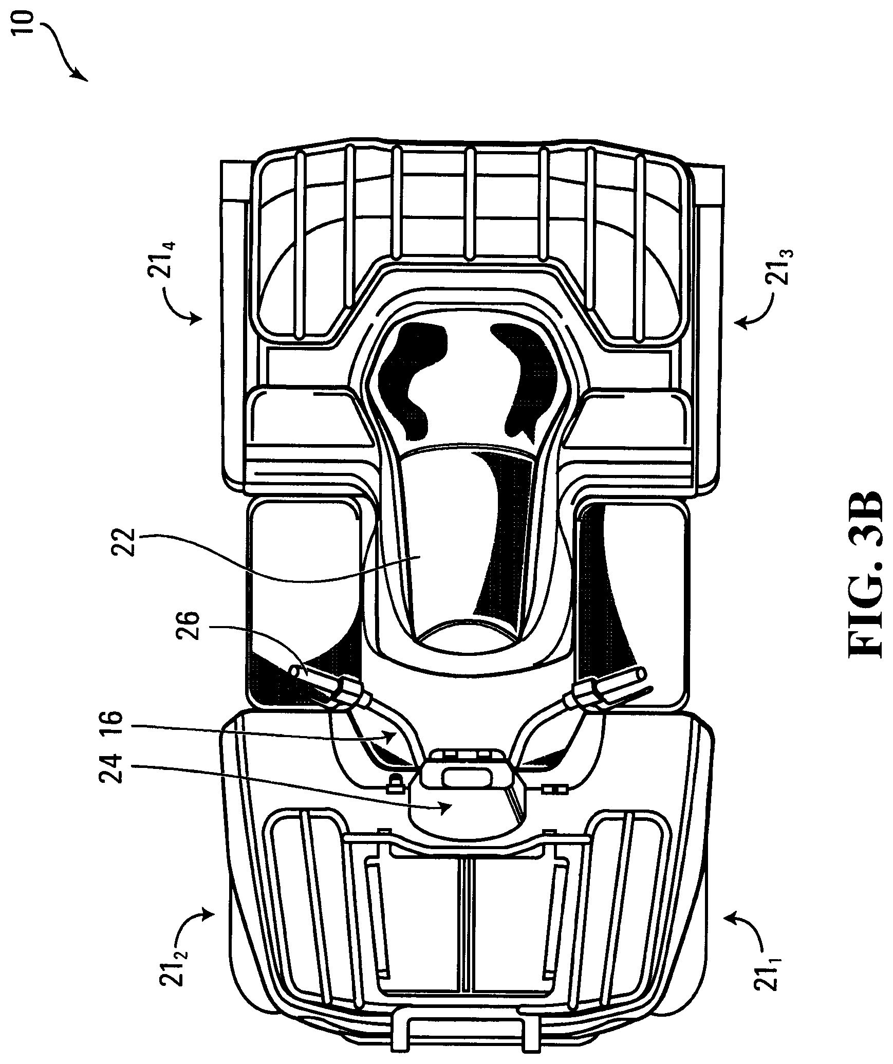
[0018] FIGS. 3A and 3B show the ATV equipped with ground-engaging wheels instead of the track systems;
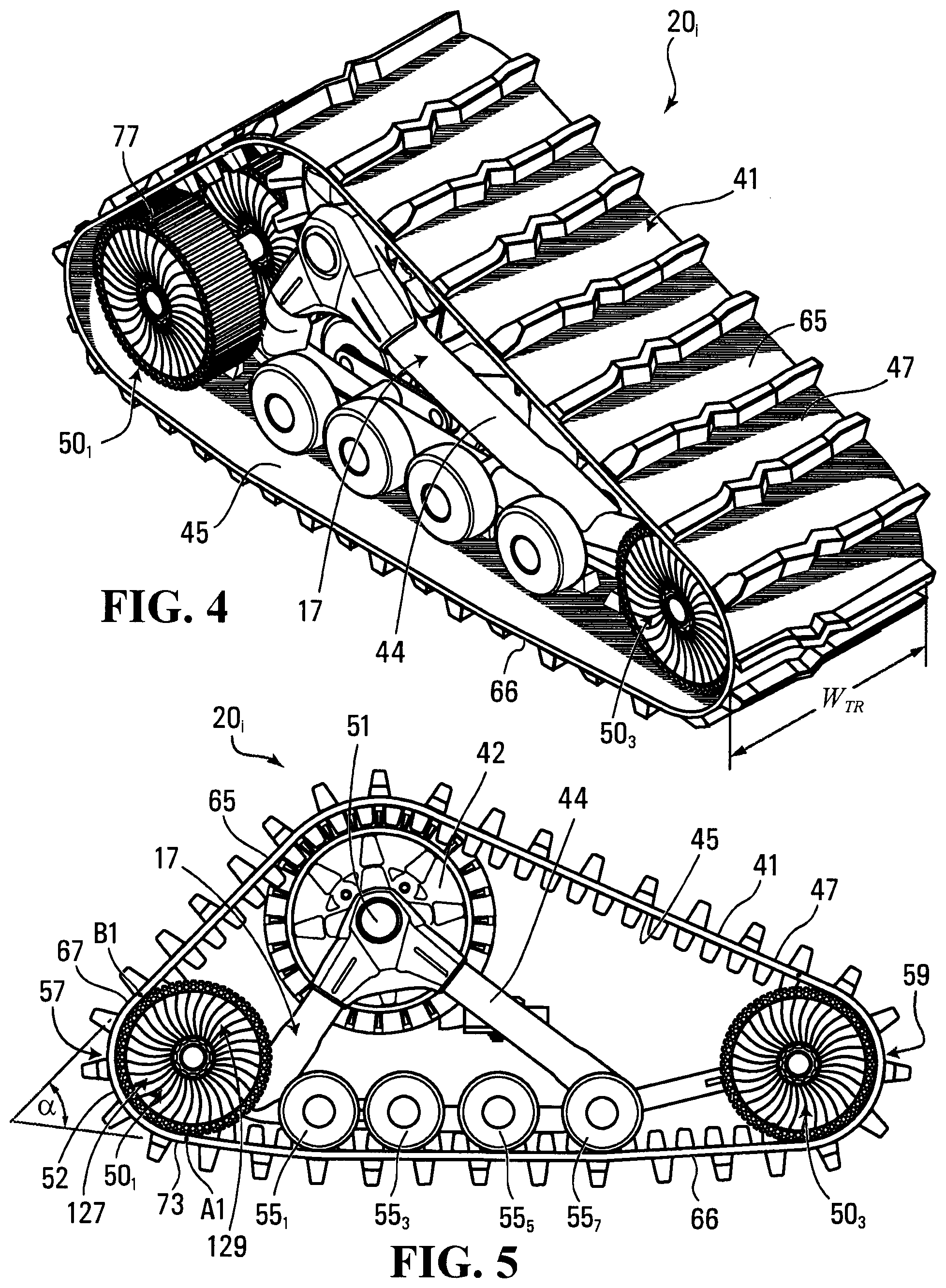
[0019] FIGS. 4 and 5 respectively show perspective and side views of a rear one of the track systems;
[0020] FIG. 6 shows a bottom view of the track system;
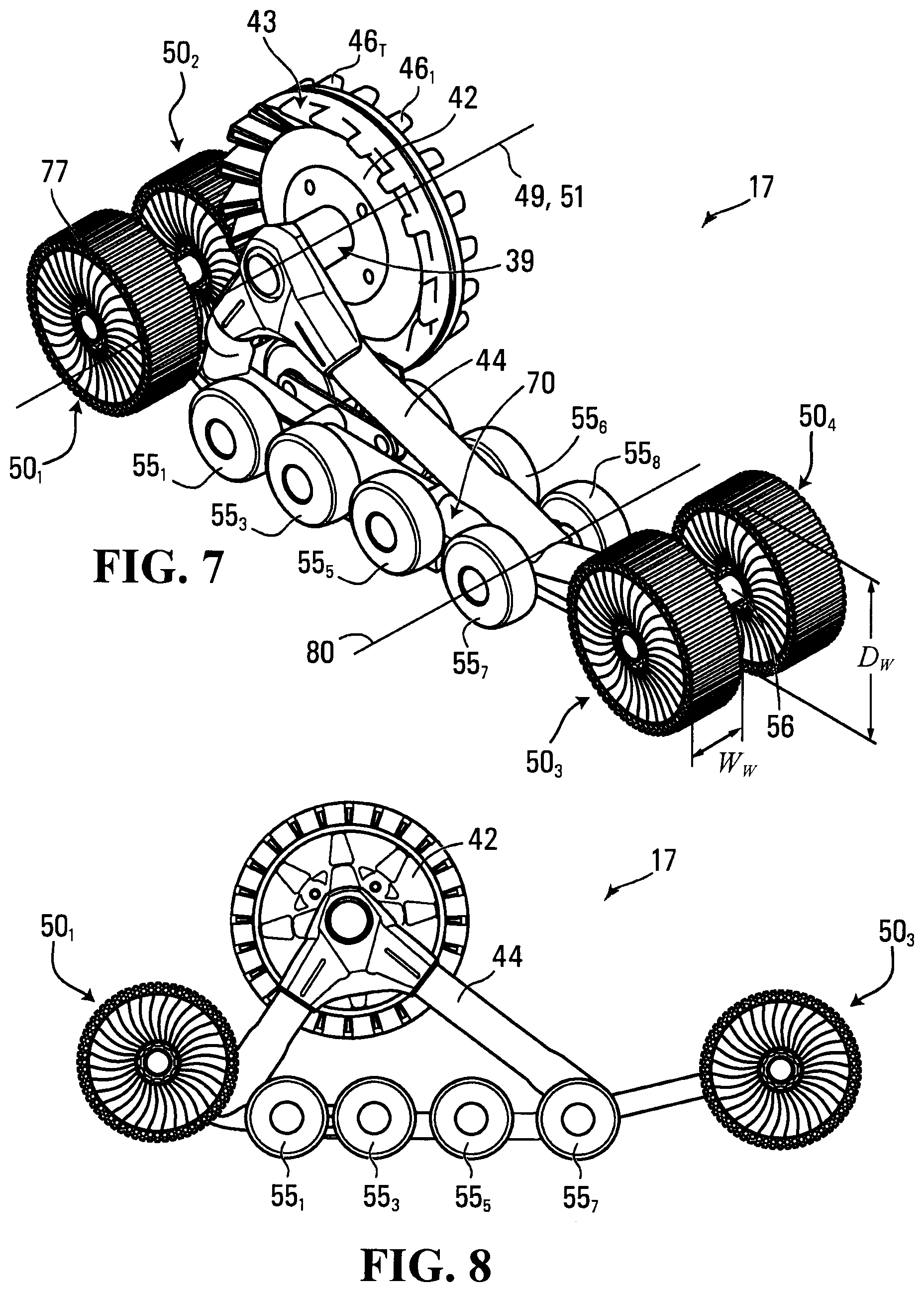
[0021] FIGS. 7 and 8 respectively show perspective and side views of the track system without its track;
[0022] FIGS. 9 and 10 show perspective views of a segment of the track of the track system, which depict features of an inner side and a ground-engaging outer side of the track;
[0023] FIG. 11 shows a side view of the track of the track system;
[0024] FIG. 12 shows a partial cross-sectional view of an embodiment of the track of the track system;
[0025] FIG. 13 shows a partial cross-sectional view of another embodiment of the track of the track system;
[0026] FIGS. 14A and 14B respectively show a side view and a perspective view of an idler wheel of the track system;
[0027] FIG. 15 shows a close-up view of part of a non-pneumatic tire of the idler wheel;
[0028] FIG. 16 shows a cross-sectional view of the idler wheel;
[0029] FIGS. 17 to 19 show representations of the idler wheel in different conditions;
[0030] FIG. 20 shows a system for measuring a radial stiffness of the idler wheel under a track tension load;
[0031] FIG. 21 shows a representation of an embodiment of the idler wheel and the track;
[0032] FIG. 22 shows the idler wheel under the track tension load;
[0033] FIG. 23 shows the idler wheel under an obstacle load;
[0034] FIG. 24 shows a chart that relates load and displacement for the idler wheel of FIGS. 22 and 23;
[0035] FIGS. 25 to 27 respectively show structural modeling results for another embodiment of the idler wheel under no load, under the track tension load, and under the obstacle load;
[0036] FIG. 28 shows a side view of a rear one of the track systems where a leading idler wheel and a trailing idler wheel are made of different materials;
[0037] FIG. 29 shows a side view of the rear one of the track systems where a number of openings of an annular beam of a non-pneumatic tire of the leading idler wheel is greater than that of a non-pneumatic tire of the trailing idler wheel.
[0038] FIG. 30 shows a side view of a rear one of the track systems where a size of one or more of the openings of the annular beam of the non-pneumatic tire of the leading idler wheel is greater than that of the non-pneumatic tire of the trailing idler wheel;
[0039] FIG. 31 shows a side view of the rear one of the track systems where a number of spokes of the non-pneumatic tire of the leading idler wheel is less than that of the non-pneumatic tire of the trailing idler wheel.
[0040] FIG. 32 shows a side view of the rear one of the track systems where a size of one or more of the spokes of the non-pneumatic tire of the leading idler wheel is less than that of the non-pneumatic tire of the trailing idler wheel.
[0041] FIG. 33 shows an example of an embodiment in which the annular beam of the non-pneumatic tire comprises a reinforcing layer;
[0042] FIG. 34 shows an example of an embodiment of the reinforcing layer;
[0043] FIG. 35 shows an example of another embodiment of the reinforcing layer;
[0044] FIG. 36 shows an example of an embodiment in which a thickness of the annular beam of the non-pneumatic tire is increased;
[0045] FIG. 37 shows an example of an agricultural vehicle comprising a track system in accordance with an embodiment of the invention; and
[0046] FIG. 38 shows a perspective view of the track system of FIG. 37.
[0047] It is to be expressly understood that the description and drawings are only for the purpose of illustrating certain embodiments and are an aid for understanding. They are not intended to be a definition of the limits of the invention.
DETAILED DESCRIPTION OF EMBODIMENTS
[0048] FIGS. 1A and 1B show an example of a vehicle 10 comprising track systems 20.sub.1-20.sub.4 in accordance with an embodiment of the invention. In this embodiment, the tracked vehicle 10 is an all-terrain vehicle (ATV), which is a small open vehicle designed to travel off-road on a variety of terrains, including roadless rugged terrain, for recreational, utility and/or other purposes. The ATV 10 comprises a frame 12, a powertrain 14, a steering system 16, a suspension 18, the track systems 20.sub.1-20.sub.4, a seat 22, and a user interface 24 which enable a user of the ATV 10 to ride the ATV 10 on the ground. The ATV 10 has a longitudinal direction, a widthwise direction and a height direction.
[0049] As further discussed later, in various embodiments, the track systems 20.sub.1-20.sub.4 may be designed (e.g., may comprise non-pneumatic tires, such as tension-based non-pneumatic tires) to enhance use or performance of the track systems 20.sub.1-20.sub.4 and/or the ATV 10, such as, for example, by being lightweight and/or by better handling loads, including, for instance, those resulting from track tension within the track systems 20.sub.1-20.sub.4 (e.g., at low speed and high torque) and/or from unevenness or other aspects of the ground, including encounters (e.g., impacts) with obstacles (e.g., rocks, portions of trees, debris, bumps, abrupt changes in ground level, etc.) on the ground (e.g., at high speed).
[0050] The powertrain 14 is configured for generating motive power and transmitting motive power to respective ones of the track systems 20.sub.1-20.sub.4 to propel the ATV 10 on the ground. To that end, the powertrain 14 comprises a prime mover 15, which is a source of motive power that comprises one or more motors. For example, in this embodiment, the prime mover 15 comprises an internal combustion engine. In other embodiments, the prime mover 15 may comprise another type of motor (e.g., an electric motor) or a combination of different types of motor (e.g., an internal combustion engine and an electric motor) for generating motive power to move the ATV 10. The prime mover 15 is in a driving relationship with one or more of the track systems 20.sub.1-20.sub.4. That is, the powertrain 14 transmits motive power generated by the prime mover 15 to one or more of the track systems 20.sub.1-20.sub.4 (e.g. via a transmission and/or a differential) in order to drive (i.e. impart motion to) these one or more of the track systems 20.sub.1-20.sub.4.
[0051] The steering system 16 is configured to enable the user to steer the ATV 10 on the ground. To that end, the steering system 16 comprises a steering device 26 that is operable by the user to direct the ATV 10 along a desired course on the ground. In this embodiment, the steering device 26 comprises handlebars. The steering device 26 may comprise a steering wheel or any other steering component that can be operated by the user to steer the ATV 10 in other embodiments. In this embodiment, the steering system 16 responds to the user interacting with the steering device 26 by turning respective ones of the track systems 20.sub.1-20.sub.4 to change their orientation relative to the frame 12 of the ATV 10 in order to cause the ATV 10 to move in a desired direction. In this example, the track systems 20.sub.1, 20.sub.2 (i.e., front ones of the track systems 20.sub.1-20.sub.4) are turnable in response to input of the user at the steering device 26 to change their orientation relative to the frame 12 of the ATV 10 in order to steer the ATV 10 on the ground. More particularly, in this example, each of the track systems 20.sub.1, 20.sub.2 (i.e., each of the front ones of the track systems 20.sub.1-20.sub.4) is pivotable about a steering axis 28 of the ATV 10 in response to input of the user at the steering device 26 in order to steer the ATV 10 on the ground. The track systems 20.sub.3, 20.sub.4 (i.e. rear ones of the track systems 20.sub.1-20.sub.4) are not turned relative to the frame 12 of the ATV 10 by the steering system 16.
[0052] The suspension 18 is connected between the frame 12 and the track systems 20.sub.1-20.sub.4 to allow relative motion between the frame 12 and the track systems 20.sub.1-20.sub.4 as the ATV 10 travels on the ground. For example, the suspension 18 enhances handling of the ATV 10 on the ground by absorbing shocks and helping to maintain traction between the track systems 20.sub.1-20.sub.4 and the ground. The suspension 18 may comprise an arrangement of springs and dampers. A spring may be a coil spring, a leaf spring, a gas spring (e.g., an air spring), or any other elastic object used to store mechanical energy. A damper (also sometimes referred to as a "shock absorber") may be a fluidic damper (e.g., a pneumatic damper, a hydraulic damper, etc.), a magnetic damper, or any other object which absorbs or dissipates kinetic energy to decrease oscillations. In some cases, a single device may itself constitute both a spring and a damper (e.g., a hydropneumatic, hydrolastic, or hydragas suspension device).
[0053] In this embodiment, the seat 22 is a straddle seat and the ATV 10 is usable by a single person such that the seat 22 accommodates only that person driving the ATV 10. In other embodiments, the seat 22 may be another type of seat, and/or the ATV 10 may be usable by two individuals, namely one person driving the ATV 10 and a passenger, such that the seat 22 may accommodate both of these individuals (e.g., behind one another or side-by-side) or the ATV 10 may comprise an additional seat for the passenger. For example, in other embodiments, as shown in FIGS. 2A and 2B, the ATV 10 may be a side-by-side ATV, sometimes referred to as a "utility terrain vehicle" or "utility task vehicle" (UTV), an example of which is shown in FIGS. 2A and 2B.
[0054] The user interface 24 allows the user to interact with the ATV 10. More particularly, the user interface 24 comprises an accelerator, a brake control, and the steering device 26 that are operated by the user to control motion of the ATV 10 on the ground. The user interface 24 also comprises an instrument panel (e.g., a dashboard) which provides indicators (e.g., a speedometer indicator, a tachometer indicator, etc.) to convey information to the user.
[0055] The track systems 20.sub.1-20.sub.4 engage the ground to provide traction to the ATV 10. More particularly, in this example, the track systems 20.sub.1, 20.sub.2 (i.e., the front ones of the track systems 20.sub.1-20.sub.4) provide front traction to the ATV 10 while the track systems 20.sub.3, 20.sub.4 (i.e. the rear ones of the track systems 20.sub.1-20.sub.4) provide rear traction to the ATV 10.
[0056] In this embodiment, as shown in FIGS. 3A and 3B, the track systems 20.sub.1-20.sub.4 are respectively mounted in place of ground-engaging wheels 21.sub.1-21.sub.4 with tires that may otherwise be mounted at positions of the track systems 20.sub.1-20.sub.4 to propel the ATV 10 on the ground. Basically, in this embodiment, the track systems 20.sub.1-20.sub.4 may be used to convert the ATV 10 from a wheeled vehicle into a tracked vehicle, thereby enhancing its traction and flotation on the ground.
[0057] With additional reference to FIGS. 4 to 8, in this embodiment, each track system 20.sub.i comprises a track-engaging assembly 17 and a track 41 disposed around the track-engaging assembly 17. In this example, the track-engaging assembly 17 comprises a frame 44 and a plurality of track-contacting wheels which includes a drive wheel 42 and a plurality of idler wheels 50.sub.1-50.sub.4, 55.sub.1-55.sub.8, which includes leading (i.e., front) idler wheels 50.sub.1, 50.sub.2, trailing (i.e., rear) idler wheels 50.sub.3, 50.sub.4, and support wheels 55.sub.1-55.sub.8 between the leading idler wheels 50.sub.1, 50.sub.2 and the trailing idler wheels 50.sub.3, 50.sub.4. The track system 20.sub.i has a front longitudinal end 57 and a rear longitudinal end 59 that define a length of the track system 20.sub.i. A width of the track system 20.sub.i is defined by a width of the track 41. The track system 20.sub.i has a longitudinal direction, a widthwise direction, and a height direction.
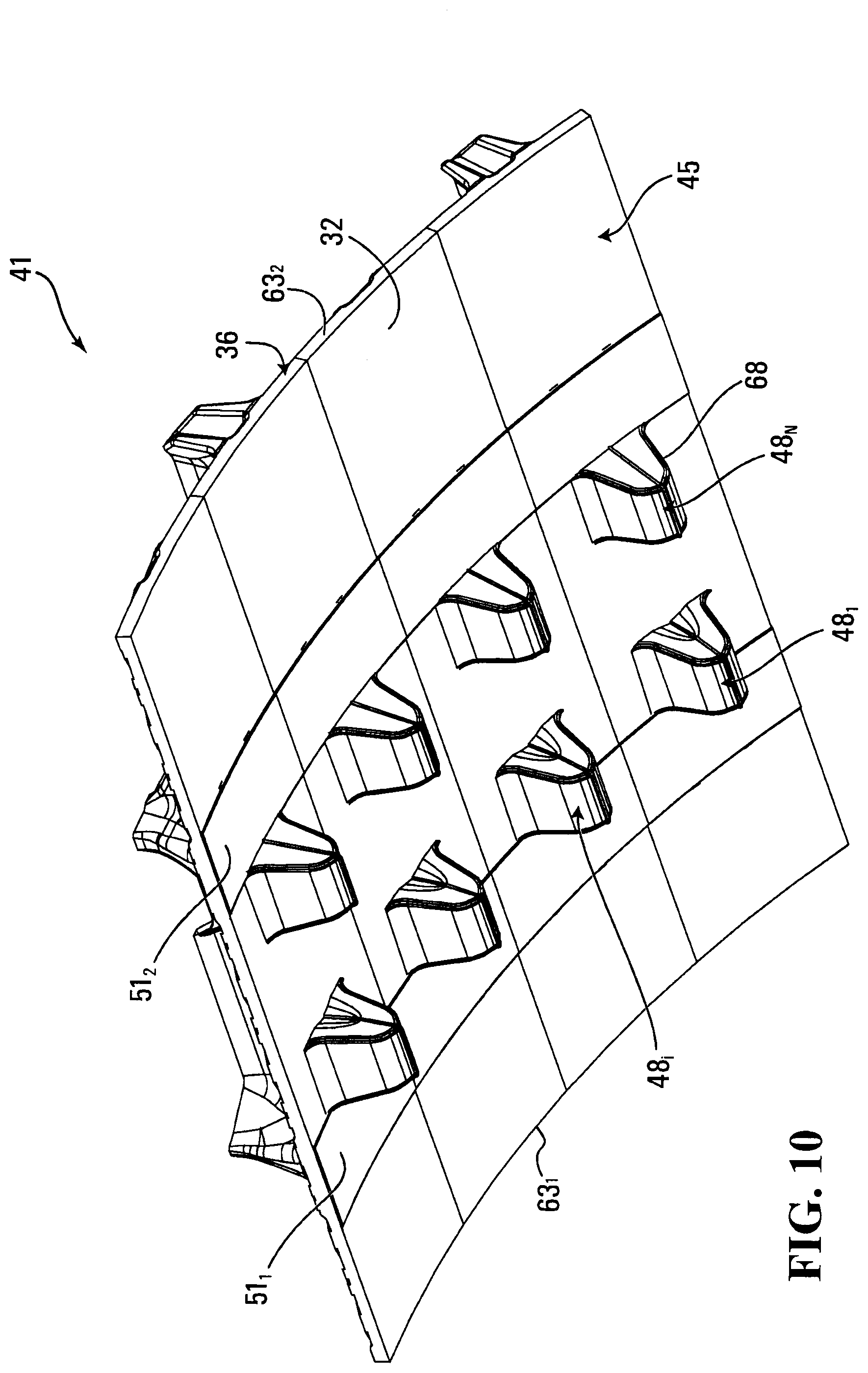
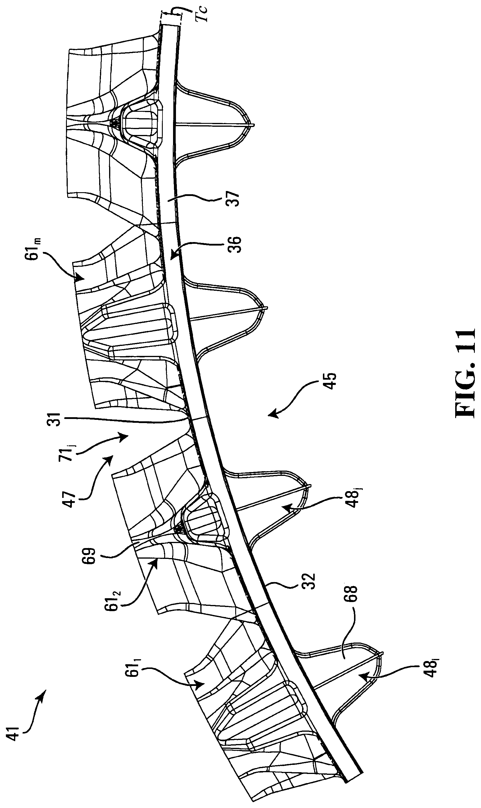
[0058] The track 41 engages the ground to provide traction to the ATV 10. A length of the track 41 allows the track 41 to be mounted around the track-engaging assembly 17. In view of its closed configuration without ends that allows it to be disposed and moved around the track-engaging assembly 17, the track 41 can be referred to as an "endless" track. Referring additionally to FIGS. 9 to 11, the track 41 comprises an inner side 45 facing the wheels 42, 50.sub.1-50.sub.4, 55.sub.1-55.sub.8 and defining an inner area of the track 41 in which these wheels are located. The track 41 also comprises a ground-engaging outer side 47 opposite the inner side 45 for engaging the ground on which the ATV 10 travels. Lateral edges 63.sub.1, 63.sub.2 of the track 41 define the track's width. The track 41 has a top run 65 which extends between the longitudinal ends 57, 59 of the track system 20.sub.i and over the track-engaging assembly 17, and a bottom run 66 which extends between the longitudinal ends 57, 59 of the track system 20.sub.i and under the track-engaging assembly 17. The track 41 has a longitudinal direction, a widthwise direction, and a thickness direction.
[0059] The track 41 is elastomeric, i.e., comprises elastomeric material, allowing it to flex around the wheels 42, 50.sub.1-50.sub.4, 55.sub.1-55.sub.8. The elastomeric material of the track 41 can include any polymeric material with suitable elasticity. In this embodiment, the elastomeric material includes rubber. Various rubber compounds may be used and, in some cases, different rubber compounds may be present in different areas of the track 41. In other embodiments, the elastomeric material of the track 41 may include another elastomer in addition to or instead of rubber (e.g., polyurethane elastomer). The track 41 can be molded into shape in a mold by a molding process during which its elastomeric material is cured.
[0060] More particularly, the track 41 comprises an elastomeric belt-shaped body 36 underlying its inner side 45 and its ground-engaging outer side 47. In view of its underlying nature, the body 36 can be referred to as a "carcass". The carcass 36 comprises elastomeric material 37 which allows the track 41 to flex around the wheels 42, 50.sub.1-50.sub.4, 55.sub.1-55.sub.8.
[0061] As shown in FIG. 12, in this embodiment, the carcass 36 comprises a plurality of reinforcements embedded in its elastomeric material 37. One example of a reinforcement is a layer of reinforcing cables 38.sub.1-38.sub.C that are adjacent to one another and that extend in the longitudinal direction of the track 41 to enhance strength in tension of the track 41 along its longitudinal direction. In some cases, a reinforcing cable may be a cord or wire rope including a plurality of strands or wires. In other cases, a reinforcing cable may be another type of cable and may be made of any material suitably flexible longitudinally (e.g., fibers or wires of metal, plastic or composite material). Another example of a reinforcement is a layer of reinforcing fabric 40. Reinforcing fabric comprises pliable material made usually by weaving, felting, or knitting natural or synthetic fibers. For instance, a layer of reinforcing fabric may comprise a ply of reinforcing woven fibers (e.g., nylon fibers or other synthetic fibers). Various other types of reinforcements may be provided in the carcass 36 in other embodiments.
[0062] The carcass 36 may be molded into shape in the track's molding process during which its elastomeric material 37 is cured. For example, in this embodiment, layers of elastomeric material providing the elastomeric material 37 of the carcass 36, the reinforcing cables 38.sub.1-38.sub.C and the layer of reinforcing fabric 40 may be placed into the mold and consolidated during molding.
[0063] In this embodiment, the inner side 45 of the track 41 comprises an inner surface 32 of the carcass 36 and a plurality of wheel-contacting projections 48.sub.1-48.sub.N that project from the inner surface 32 to contact at least some of the wheels 42, 50.sub.1-50.sub.4, 55.sub.1-55.sub.8 and that are used to do at least one of driving (i.e., imparting motion to) the track 41 and guiding the track 41. In that sense, the wheel-contacting projections 48.sub.1-48.sub.N can be referred to as "drive/guide projections", meaning that each drive/guide projection is used to do at least one of driving the track 41 and guiding the track 41. Also, such drive/guide projections are sometimes referred to as "drive/guide lugs" and will thus be referred to as such herein. More particularly, in this embodiment, the drive/guide lugs 48.sub.1-48.sub.N interact with the drive wheel 42 in order to cause the track 41 to be driven, and also interact with the idler wheels 50.sub.1-50.sub.4, 55.sub.1-55.sub.8 in order to guide the track 41 as it is driven by the drive wheel 42. The drive/guide lugs 48.sub.1-48.sub.N are thus used to both drive the track 41 and guide the track 41 in this embodiment.
[0064] The drive/guide lugs 48.sub.1-48.sub.N are spaced apart along the longitudinal direction of the track 41. In this case, the drive/guide lugs 48.sub.1-48.sub.N are arranged in a plurality of rows that are spaced apart along the widthwise direction of the track 41. The drive/guide lugs 48.sub.1-48.sub.N may be arranged in other manners in other embodiments (e.g., a single row or more than two rows). Each of the drive/guide lugs 48.sub.1-48.sub.N is an elastomeric drive/guide lug in that it comprises elastomeric material 68. The drive/guide lugs 48.sub.1-48.sub.N can be provided and connected to the carcass 36 in the mold during the track's molding process.
[0065] The ground-engaging outer side 47 of the track 41 comprises a ground-engaging outer surface 31 of the carcass 36 and a plurality of traction projections 61.sub.1-61.sub.M that project from the outer surface 31 and engage and may penetrate into the ground to enhance traction. The traction projections 61.sub.1-61.sub.M, which can sometimes be referred to as "traction lugs" or "traction profiles", are spaced apart in the longitudinal direction of the track system 20.sub.i. The ground-engaging outer side 47 comprises a plurality of traction-projection-free areas 71.sub.1-71.sub.F (i.e., areas free of traction projections) between successive ones of the traction projections 61.sub.1-61.sub.M. In this example, each of the traction projections 61.sub.1-61.sub.M is an elastomeric traction projection in that it comprises elastomeric material 69. The traction projections 61.sub.1-61.sub.M can be provided and connected to the carcass 36 in the mold during the track's molding process.
[0066] Each traction projection 61.sub.i extends transversally to the longitudinal direction of the track 41. That is, the traction projection 61.sub.i has a longitudinal axis 54 extending transversally to the longitudinal direction of the track 41. In this example, the longitudinal axis 54 of the traction projection 61.sub.i is substantially parallel to the widthwise direction of the track 41. In other examples, the longitudinal axis 54 of the traction projection 61.sub.i may be transversal to the longitudinal direction of the track 41 without being parallel to the widthwise direction of the track 41.
[0067] In this example, the carcass 36 has a thickness T.sub.c which is relatively small. The thickness T.sub.c of the carcass 36 is measured from the inner surface 32 to the ground-engaging outer surface 31 of the carcass 35 between longitudinally-adjacent ones of the traction projections 61.sub.1-61.sub.M. For example, in some embodiments, the thickness T.sub.c of the carcass 36 may be no more than 0.375 inches, in some cases no more than 0.325 inches, in some cases no more than 0.275 inches, in some cases no more than 0.225 inches, in some cases no more than 0.200 inches, and in some cases even less (e.g., 0.180 or 0.170 inches). The thickness T.sub.c of the carcass 36 may have any other suitable value in other embodiments.
[0068] In this embodiment, as shown in FIG. 12, the track 41 is free of transversal stiffening rods embedded in its elastomeric material. That is, the track 41 does not comprise transversal stiffening rods embedded in its elastomeric material and extending transversally to its longitudinal direction. FIG. 13 shows a variant in which the track 41 may comprise transversal stiffening rods 53.sub.1-53.sub.M embedded in its elastomeric material and extending transversally to its longitudinal direction in other embodiments. This absence of transversal stiffening rods makes the track 41 more flexible in its widthwise direction than if the track 41 had the transversal stiffening rods 53.sub.1-53.sub.M but was otherwise identical.
[0069] The track 41 may be constructed in various other ways in other embodiments. For example, in some embodiments, the track 41 may comprise a plurality of parts (e.g., rubber sections) interconnected to one another in a closed configuration, the track 41 may have recesses or holes that interact with the drive wheel 42 in order to cause the track 41 to be driven (e.g., in which case the drive/guide lugs 48.sub.1-48.sub.N may be used only to guide the track 41 without being used to drive the track 41), and/or the ground-engaging outer side 47 of the track 41 may comprise various patterns of traction projections.
[0070] The drive wheel 42 is rotatable about an axis of rotation 49 for driving the track 41 in response to rotation of an axle of the ATV 10. In this example, the axis of rotation 49 corresponds to the axle of the ATV 10. More particularly, in this example, the drive wheel 42 has a hub which is mounted to the axle of the ATV 10 such that power generated by the prime mover 15 and delivered over the powertrain 14 of the ATV 10 rotates the axle, which rotates the drive wheel 42, which imparts motion of the track 41. In this embodiment in which the track system 20.sub.i is mounted where a ground-engaging wheel 21.sub.i could otherwise be mounted, the axle of the ATV 10 is capable of rotating the drive wheel 42 of the track system 20.sub.i or the ground-engaging wheel 21.sub.i.
[0071] In this embodiment, the drive wheel 42 comprises a drive sprocket 43 engaging the drive/guide lugs 48.sub.1-48.sub.N of the inner side 45 of the track 41 in order to drive the track 41. In this case, the drive sprocket 43 comprises a plurality of teeth 46.sub.1-46.sub.T distributed circumferentially along its rim to define a plurality of lug-receiving spaces therebetween that receive the drive/guide lugs 48.sub.1-48.sub.N of the track 41. The drive wheel 42 may be configured in various other ways in other embodiments. For example, in embodiments where the track 41 comprises recesses or holes, the drive wheel 42 may have teeth that enter these recesses or holes in order to drive the track 41. As yet another example, in some embodiments, the drive wheel 42 may frictionally engage the inner side 45 of the track 41 in order to frictionally drive the track 41.
[0072] The idler wheels 50.sub.1-50.sub.4, 55.sub.1-55.sub.8 are not driven by power supplied by the prime mover 15, but are rather used to do at least one of supporting part of the weight of the ATV 10 on the ground via the track 41, guiding the track 41 as it is driven by the drive wheel 42, and tensioning the track 41.
[0073] Each of the idler wheels 50.sub.1-50.sub.4, 55.sub.1-55.sub.8 has an axial direction defined by an axis of rotation 80 of that idler wheel (also referred to as a "Y" direction), a radial direction (also referred to as a "Z" direction), and a circumferential direction (also referred to as a "X" direction). Each of the idler wheels 50.sub.1-50.sub.4, 55.sub.1-55.sub.8 has an outer diameter D.sub.W and a width W.sub.W and comprises an inboard lateral side 47 for facing a center of the ATV 10 in the widthwise direction of the ATV 10 and an outboard lateral side 49 opposite the inboard lateral side 47. Each of the idler wheels 50.sub.1-50.sub.4, 55.sub.1-55.sub.8 has an area of contact 25 with the inner side 45 of the track 41 that has a dimension L.sub.C, referred to as a "length", in the circumferential direction of that idler wheel and a dimension W.sub.C, referred to as a "width", in the axial direction of that idler wheel.
[0074] More particularly, in this embodiment, the leading idler wheels 50.sub.1, 50.sub.2 and the trailing idler wheels 50.sub.3, 50.sub.4 maintain the track 41 in tension and can help to support part of the weight of the ATV 10 on the ground via the track 41. The leading idler wheels 50.sub.1, 50.sub.2 are spaced apart along the widthwise direction of the track system 20.sub.i, and so are the trailing idler wheels 50.sub.3, 50.sub.4.
[0075] Each idler wheel 50.sub.x of the leading and trailing idler wheels 50.sub.1-50.sub.4 contacts the inner side 45 of the track 41 such that a longitudinal end segment 52 of the track 41 turns about the idler wheel 50.sub.x. That is, the idler wheel 50.sub.x contacts both the top run 65 of the track 41 and the bottom run 66 of the track 41 such that the longitudinal end segment 52 of the track 41 includes a longitudinal end part 67 of the top run 65 of the track 41 and a longitudinal end part 73 of the bottom run 66 of the track 41. In this embodiment, the longitudinal end segment 52 of the track 41 is located between the axis of rotation 80 of the idler wheel 50.sub.x and a given one of the longitudinal ends 57, 59 of the track system 20.sub.i that is adjacent to the idler wheel 50.sub.x. Thus, in this example, the longitudinal end segment 52 of the track 41 is that segment of the track 41 between points A.sub.1 and B.sub.1 and defines an an angle of wrap a of the track 41 about the idler wheel 50.sub.x.
[0076] The idler wheels 55.sub.1-55.sub.8 are roller wheels that roll on the inner side 45 of the track 41 along the bottom run 66 of the track 41 to apply the bottom run 66 on the ground. The idler wheels 55.sub.1-55.sub.8 move on respective ones of a plurality of idler wheel paths 51.sub.1, 51.sub.2 of the inner surface 32 of the carcass 35 of the track 41. Each of the idler wheel paths 51.sub.1, 51.sub.2 extends adjacent to respective ones of the drive/guide lugs 48.sub.1-48.sub.N to allow these lugs to guide motion of the track 41. As the roller wheels 55.sub.1-55.sub.8 roll on respective ones of the idler wheel paths 51.sub.1, 51.sub.2, these paths can be referred to as "rolling paths".
[0077] In some embodiments, one or more of the idler wheels 50.sub.1-50.sub.4, 55.sub.1-55.sub.8 may be resiliently deformable as the track 41 moves around them, including in response to encountering obstacles of the ground (e.g., rocks, portions of trees, debris, bumps, abrupt changes in ground level, etc.). This may help to absorb shocks when the track system 20.sub.i encounters obstacles and/or may make it easier for the track system 20.sub.i to surmount obstacles.
[0078] That is, in some embodiments, an idler wheel 50.sub.i or 55.sub.i may deform under load and regain its original shape upon removal of the load. The idler wheel 50.sub.i or 55.sub.i comprises a resiliently-deformable wheel portion 77. For example, in some embodiments, the resiliently-deformable wheel portion 77 may comprise a tire. For instance, in some embodiments, the tire may be a non-pneumatic tire. In other embodiments, the tire may be a pneumatic tire.
[0079] For example, in some embodiments, each idler wheel 50.sub.x of the leading and trailing idler wheels 50.sub.1-50.sub.4 may be resiliently deformable in response to encountering obstacles. By resiliently deforming, the idler wheel 50.sub.x allows a change in curvature of the longitudinal end segment 52 of the track 41 when the longitudinal end segment 52 of the endless track 41 contacts an obstacle on the ground. For instance, when the longitudinal end segment 52 of the track 41 adjacent to the idler wheel 50.sub.x contacts an obstacle as the ATV 10 moves, the idler wheel 50.sub.x can elastically deform, by being elastically compressed under load, to allow a change in curvature of the longitudinal end segment 52 of the track 41 in order to generally conform to a contacted part of the obstacle. This elastic deformation of the idler wheel 50.sub.x absorbs at least part of a shock resulting from contact with the obstacle. Also, the change in curvature of the longitudinal end segment 52 of the track 41 may enhance its traction on the obstacle and can thus facilitate climbing of the track system 16.sub.i over the obstacle. As the obstacle is surmounted and stress on the idler wheel 50.sub.x that had been compressed is reduced, the idler wheel 50.sub.x can regain its original shape.
[0080] The idler wheels 50.sub.1-50.sub.4, 55.sub.1-55.sub.8 may be arranged in other configurations and/or the track system 20.sub.i may comprise more or less idler wheels in other embodiments.
[0081] The frame 44 supports components of the track system 20.sub.i, including the idler wheels 50.sub.1-50.sub.4, 55.sub.1-55.sub.8. More particularly, in this embodiment, the front idler wheels 50.sub.1, 50.sub.2 are mounted to the frame 44 in a front longitudinal end region of the frame 44 proximate the front longitudinal end 57 of the track system 20.sub.i, while the rear idler wheels 50.sub.3, 50.sub.4 are mounted to the frame 44 in a rear longitudinal end region of the frame 44 proximate the rear longitudinal end 59 of the track system 20.sub.i. The roller wheels 55.sub.1-55.sub.8 are mounted to the frame 44 in a central region of the frame 44 between the front idler wheels 50.sub.1, 50.sub.2 and the rear idler wheels 50.sub.3, 50.sub.4. Each of the roller wheels 55.sub.1-55.sub.8 may be rotatably mounted directly to the frame 44 or may be rotatably mounted to a link which is pivotally mounted to the frame 44 to which is rotatably mounted an adjacent one of the roller wheels 55.sub.1-55.sub.8, thus forming a "tandem".
[0082] The frame 44 is supported at a support area 39. More specifically, in this case, the frame 44 is supported by the axle of the ATV 10 to which is coupled the drive wheel 42, such that the support area 39 is intersected by the axis of rotation 49 of the drive wheel 42.
[0083] In this embodiment, the track system 20.sub.i is movable relative to the frame 12 of the ATV 10, such as when the ATV 10 travels on uneven terrain. More particularly, the frame 44 of the track system 20.sub.i is movable relative to the frame 12 of the ATV 10 to facilitate motion of the track system 20.sub.i on uneven terrain and enhance its traction on the ground. The frame 44 of the track system 20.sub.i is pivotable relative to the frame 12 of the ATV 10 about a pivot axis 51. More specifically, in this embodiment, the pivot axis 51 corresponds to the axis of rotation 49 of the drive wheel 42 and the frame 44 can pivot about the axle of the ATV 10 to which the drive wheel 42 is coupled. In other embodiments, the pivot axis 51 of the frame 44 may be located elsewhere (e.g., lower) than the axis of rotation 49 of the drive wheel 42.
[0084] The idler wheels 50.sub.1-50.sub.4, 55.sub.1-55.sub.8 may be designed to enhance use or performance of the track system 20.sub.i and/or the ATV 10, such as, for example, by being lightweight and/or by better handling loads, including, for instance, those resulting from tension of the track 41 (e.g., at low speed and high torque) and/or from unevenness or other aspects of the ground, including impacts with obstacles on the ground (e.g., at high speed).
[0085] Examples of embodiments in which this may be achieved in respect of the leading and trailing idler wheels 50.sub.1-50.sub.4 are discussed below.
1. Idler Wheel Comprising a Non-Pneumatic Tire (NPT)
[0086] In some embodiments, as shown in FIGS. 14 to 18, each idler wheel 50.sub.x of the leading and trailing idler wheels 50.sub.1-50.sub.4 comprises a non-pneumatic tire 58 and a hub 75 for connecting the idler wheel 50.sub.x to the frame 44 of the track system 20.sub.i. The non-pneumatic tire 58 is a compliant wheel structure that is not supported by gas (e.g., air) pressure and that is resiliently deformable (i.e., resiliently changeable in configuration) as the track system 20.sub.i contacts the ground.
[0087] The non-pneumatic tire 58 comprises an annular beam 136 and an annular support 141 that is disposed between the annular beam 136 and the hub 75 and configured to support loading on the idler wheel 50.sub.x as the track system 20.sub.i engages the ground. In this embodiment, the non-pneumatic tire 58 is tension-based such that the annular support 141 is configured to support the loading on the idler wheel 50.sub.x by tension. That is, under the loading on the idler wheel 50.sub.x (i.e., due to loading on the track system 20.sub.i, the tension of the track 41, etc.), the annular support 141 is resiliently deformable such that a portion 127 of the annular support 141 between the axis of rotation 80 of the idler wheel 50.sub.x and the area of contact 25 of the idler wheel 50.sub.x with the track 41 is compressed and a portion 129 of the annular support 141 between the axis of rotation 80 of the idler wheel 50.sub.x and a peripheral part 27 of the idler wheel 50.sub.x not in contact with the track 41 is in tension to support the loading.
[0088] The annular beam 136 of the non-pneumatic tire 58 is configured to deflect under the loading on the idler wheel 50.sub.x at the area of contact 25 of the idler wheel 50.sub.x with the track 41. in some situations, depending on the loading on the idler wheel 50.sub.x (e.g., such as when the idler wheel 50.sub.x encounters an obstacle on the ground), as discussed later, the annular beam 136 can function like a beam in transverse deflection. An outer peripheral extent 146 of the annular beam 136 and an inner peripheral extent 148 of the annular beam 136 deflect at the area of contact 25 of the idler wheel 50.sub.x with the inner side 45 of the track 41 under the loading on the idler wheel 50.sub.x.
[0089] More particularly, in this embodiment, the annular beam 136 comprises a shear band 139. In some situations, such as when the idler wheel 50.sub.x encounters an obstacle on the ground, the shear band 139 is configured to deflect predominantly by shearing at the area of contact 25 of the idler wheel 50.sub.x with the track 41 under the loading on the idler wheel 50.sub.x. That is, under the loading on the idler wheel 50.sub.x when encountering an obstacle on the ground, the shear band 139 deflects significantly more by shearing than by bending at the area of contact 25 of the idler wheel 50.sub.x with the track 41. The shear band 139 is thus configured such that, at a center of the area of contact 25 of the idler wheel 50.sub.x with the track 41 in the circumferential direction of the idler wheel 50.sub.x, a shear deflection of the shear band 139 is significantly greater than a bending deflection of the shear band 139. For example, in some embodiments, at the center of the area of contact 25 of the idler wheel 50.sub.x with the track 41 in the circumferential direction of the idler wheel 50.sub.x, a ratio of the shear deflection of the shear band 139 over the bending deflection of the shear band 139 may be at least 1.2, in some cases at least 1.5, in some cases at least 2, in some cases at least 3, and in some cases even more (e.g., 4 or more). For instance, in some embodiments, the annular beam 136 may be designed based on principles discussed in U.S. Patent Application Publication 2014/0367007, which is hereby incorporated by reference herein.
[0090] The annular beam 136 therefore has a high bending stiffness and a comparatively low shear stiffness. As such, the annular beam 136, including the shear band 139, will deflect due to a shear force more easily than it will deflect due to a bending moment. The loading to which the annular beam 136 of the idler wheel 50.sub.x is subjected to can be at least predominantly bending-based or at least predominately shear-based in various situations, explained as follows: [0091] At least predominantly bending-based (i.e., predominantly or entirely bending-based): with reference to FIGS. 21 and 22, a portion 117 of the annular beam 136 corresponding to the peripheral part 27 of the idler wheel 50.sub.x not in contact with the track 41 functions like an arch. This arch supports tension loads from the portion 129 of the annular support 141 between the axis of rotation 80 of the idler wheel 50.sub.x and the peripheral part 27 of the idler wheel 50.sub.x not in contact with the track 41 and transmits a large bending moment. This can occur when the loading on the idler wheel 50.sub.x is at least predominantly due to the tension of the track 41 in contact with it in normal operation without any obstacle encountering the idler wheel 50.sub.x. [0092] At least predominantly shear-based (i.e., predominantly or entirely shear-based): in FIGS. 18, 19, and 23, a portion 119 of the annular beam 136 is subjected to a transverse deflection which is accompanied by large shear forces acting on the annular beam 136. This may occur, for instance, when the idler wheel 50.sub.x encounters an obstacle on the ground. In the case of FIGS. 18 and 19, the annular beam 136 is loaded against a flat surface, which can represent what happens when the obstacle is mild. In the case of FIG. 23, the annular beam 136 is loaded against a sharp object, which can represent what happens when the obstacle is more severe.
[0093] Since it is stiff in bending and compliant in shear, the annular beam 136 will be stiff, with little deflection, in the load case of FIG. 22, and, conversely, will deflect comparatively easily for the load cases shown in FIGS. 18, 19, and 23 in which the transverse beam deflection due to shear will be higher than the deflection due to bending.
[0094] The idler wheel 50.sub.x does, however, deflect when subjected to the load of FIG. 22. This is due to bending of elements (e.g., spokes) of the portion 127 of the annular support 141 between the axis of rotation 80 of the idler wheel 50.sub.x and the area of contact 25 of the idler wheel 50.sub.x with the track 41 that are compressed.
[0095] The annular beam 136 remains basically an annular form which is translated (e.g., up in this figure) due to tensile forces of the track 41 shown in FIG. 21. This movement can sometimes be referred to a counter deflection. Yet, as the load is also supported in tension by elements (e.g., spokes) of the portion 129 of the annular support 141 between the axis of rotation 80 of the idler wheel 50.sub.x and the peripheral part 27 of the idler wheel 50.sub.x not in contact with the track 41, the idler wheel 50.sub.x develops only a small deflection, even when subjected to large track loads under normal operation.
[0096] Through extensive numerical and physical testing, the inventors have developed useful relationships between deflection due to bending and deflection due to shear, for cases where the annular beam 136 is subjected to a transverse deflection. This can occur during an encounter with an obstacle on the ground, such as an impact with the obstacle. While the physics of an obstacle impact, such as shown in FIG. 23, may be complex, this can be related to the simple case shown in FIG. 19 where an impact occurs when loaded against a flat surface. For example, in some embodiments, a contact length L.sub.IMPACT equal to 40% of the outer diameter D.sub.W of the idler wheel 50.sub.x correlates to a moderate to severe impact deflection.
[0097] When the deflection due to shear is higher than the deflection due to bending, the annular beam 136 becomes fairly complaint in transverse beam deflection. This may be very favorable to operation of the track system 20.sub.i, as it may decouple a stiffness of the idler wheel 50.sub.x in normal operation to the stiffness of the idler wheel 50.sub.x in impact loading, which will be further discussed in a later section.
[0098] For instance, in some embodiments, the inventors have found that a ratio of a deflection due to bending to a deflection due to shear of 2:1 when the annular beam 136 is loaded against a flat surface to a contact length of 40% of the outer diameter of the idler wheel 50.sub.x may provide good wheel performance. In some embodiments, this ratio can be 3:1, in others 4:1, and in some cases even higher.
[0099] In this example of implementation, the shear band 139 comprises an outer rim 131, an inner rim 133, and a plurality of openings 156.sub.1-156.sub.N between the outer rim 131 and the inner rim 133. The shear band 139 comprises a plurality of interconnecting members 137.sub.1-137.sub.P that extend between the outer rim 131 and the inner rim 133 and are disposed between respective ones of the openings 156.sub.1-156.sub.N. The interconnecting members 137.sub.1-137.sub.P may be referred to as "webs" such that the shear band 139 may be viewed as being "web-like" or "webbing". The shear band 139, including the openings 156.sub.1-156.sub.N and the interconnecting members 137.sub.1-137.sub.P, may be arranged in any other suitable way in other embodiments.
[0100] The openings 156.sub.1-156.sub.N of the shear band 139 help the shear band 139 to deflect predominantly by shearing at the area of contact 25 of the idler wheel 50.sub.x with the track 41 under the loading on the idler wheel 50.sub.x in some situations as discussed above. In this embodiment, the openings 156.sub.1-156.sub.N extend from the inboard lateral side 147 to the outboard lateral side 149 of the non-pneumatic tire 58. That is, the openings 156.sub.1-156.sub.N extend laterally though the shear band 139 in the axial direction of the idler wheel 50.sub.x. The openings 156.sub.1-156.sub.N may extend laterally without reaching the inboard lateral side 147 and/or the outboard lateral side 149 of the non-pneumatic tire 58 in other embodiments. The openings 156.sub.1-156.sub.N may have any suitable shape. In this example, a cross-section of each of the openings 156.sub.1-156.sub.N is circular. The cross-section of each of the openings 156.sub.1-156.sub.N may be shaped differently in other examples (e.g., polygonal, partly curved and partly straight, etc.). In some cases, different ones of the openings 156.sub.1-156.sub.N may have different shapes. In some cases, the cross-section of each of the openings 156.sub.1-156.sub.N may vary in the axial direction of the idler wheel 50.sub.x. For instance, in some embodiments, the openings 156.sub.1-156.sub.N may be tapered in the axial direction of the idler wheel 50.sub.x such that their cross-section decreases inwardly axially (e.g., to help minimize debris accumulation within the openings 156.sub.1-156.sub.N).
[0101] In this embodiment, the non-pneumatic tire 58 comprises a tread 150 for engaging the track 41. The tread 150 may enhance frictional engagement (e.g., "gripping") of the idler wheel 50.sub.x on the inner surface 32 of the track 41. The tread 150 is disposed about the outer peripheral extent 146 of the annular beam 136, in this case about the outer rim 131 of the shear band 139. More particularly, in this example the tread 150 comprises a tread base 143 that is at the outer peripheral extent of the tread 150 and a plurality of tread recesses 152.sub.1-152.sub.T that project from the tread base 143 towards the axis of rotation 80 of the idler wheel 50.sub.x in the radial direction of the non-pneumatic tire 58. The tread recesses 152.sub.1-152.sub.T are spaced apart in the circumferential direction of the non-pneumatic tire 58 and extend across at least a majority of a width W.sub.T of the non-pneumatic tire. More particularly, in this example, the tread recesses 152.sub.1-152.sub.T extends across substantially an entirety of the width W.sub.T of the non-pneumatic tire 58. The tread 150 may be implemented in any other suitable way in other embodiments (e.g., may comprise a plurality of tread projections, etc.).
[0102] The annular support 141 is configured to support the loading on the idler wheel 50.sub.x as the track system 20.sub.i engages the ground. As mentioned above, in this embodiment, the annular support 141 is configured to support the loading on the idler wheel 50.sub.x by tension. More particularly, in this embodiment, the annular support 141 comprises a plurality of support members 142.sub.1-142.sub.T that are distributed around the non-pneumatic tire 58 and resiliently deformable such that, under the loading on the idler wheel 50.sub.x, respective ones of the support members 142.sub.1-142.sub.T in the portion 127 of the annular support 141 between the axis of rotation 80 of the idler wheel 50.sub.x and the area of contact 25 of the idler wheel 50.sub.x with the track 41 are compressed and bend while other ones of the support members 142.sub.1-142.sub.T in the portion 129 of the annular support 141 between the axis of rotation 80 of the idler wheel 50.sub.x and the peripheral part 27 of the idler wheel 50.sub.x not in contact with track 41 are tensioned to support the loading. As they support load by tension when in the portion 129 of the annular support 141, the support members 142.sub.1-142.sub.T may be referred to as "tensile" members.
[0103] In this embodiment, the support members 142.sub.1-142.sub.T are elongated and extend from the annular beam 136 towards the hub 75 generally in the radial direction of the idler wheel 50.sub.x. In that sense, the support members 142.sub.1-142.sub.T may be referred to as "spokes" and the annular support 141 may be referred to as a "spoked" support.
[0104] More particularly, in this embodiment, the inner peripheral extent 148 of the annular beam 136 is an inner peripheral surface of the annular beam 136 and each spoke 142.sub.i extends from the inner peripheral surface 148 of the annular beam 136 towards the hub 75 generally in the radial direction of the idler wheel 50.sub.x and from a first lateral end 155 to a second lateral end 158 in the axial direction of the idler wheel 50.sub.x. In this case, the spoke 142.sub.i extends in the axial direction of the idler wheel 50.sub.x for at least a majority of a width W.sub.T of the non-pneumatic tire 58, which in this case corresponds to the width W.sub.W of the idler wheel 50.sub.x. For instance, in some embodiments, the spoke 142.sub.i may extend in the axial direction of the idler wheel 50.sub.x for more than half, in some cases at least 60%, in some cases at least 80%, and in some cases an entirety of the width W.sub.T of the non-pneumatic tire 58. Moreover, the spoke 142.sub.i has a thickness T.sub.S measured between a first surface face 159 and a second surface face 161 of the spoke 142.sub.i that is significantly less than a length and width of the spoke 142.sub.i.
[0105] When the track system 20.sub.i moves on the ground, respective ones of the spokes 142.sub.1-142.sub.T that are disposed in the portion 129 of the spoked support 141 between the axis of rotation 80 of the idler wheel 50.sub.x and the peripheral part 27 of the idler wheel 50.sub.x not in contact with track 41 are placed in tension while respective ones of the spokes 142.sub.1-142.sub.T that are disposed in the portion 127 of the spoked support 141 between the area of contact 25 of the idler wheel 50.sub.x with the track 41 are placed in compression. The spokes 142.sub.1-142.sub.T in the portion 127 of the spoked support 141 which are in compression bend in response to the load. Conversely, the spokes 142.sub.1-142.sub.T in the portion 129 of the spoked support 141 which are placed in tension support the load by tension.
[0106] The non-pneumatic tire 58 has an inner diameter D.sub.TI and an outer diameter D.sub.TO, which in this case corresponds to the outer diameter D.sub.W of the leading idler wheels 50.sub.1, 50.sub.2. A sectional height H.sub.T of the non-pneumatic tire 58 is half of a difference between the outer diameter D.sub.TO and the inner diameter D.sub.TI of the non-pneumatic tire 58. The sectional height H.sub.T of the tire may be significant in relation to the width W.sub.T of the non-pneumatic tire 58. In other words, an aspect ratio AR of the non-pneumatic tire 58 corresponding to the sectional height H.sub.T over the width W.sub.T of the non-pneumatic tire 58 may be relatively high. For instance, in some embodiments, the aspect ratio AR of the non-pneumatic tire 58 may be at least 70%, in some cases at least 90%, in some cases at least 110%, and in some cases even more. Also, the inner diameter D.sub.TI of the non-pneumatic tire 58 may be significantly less than the outer diameter D.sub.TO of the non-pneumatic tire 58 as this may help for compliance of the idler wheel 50.sub.x. For example, in some embodiments, the inner diameter D.sub.TI of the non-pneumatic tire 58 may be no more than half of the outer diameter D.sub.TO of the non-pneumatic tire 58, in some cases less than half of the outer diameter D.sub.TO of the non-pneumatic tire 58, in some cases no more than 40% of the outer diameter D.sub.TO of the non-pneumatic tire 58, in some cases no more than 30% of the outer diameter D.sub.TO of the non-pneumatic tire 58, and in some cases even a smaller fraction of the outer diameter D.sub.TO of the non-pneumatic tire 58.
[0107] In this embodiment, the width W.sub.T of the non-pneumatic tire 58, which corresponds to the width W.sub.w of the idler wheel 50.sub.x in this case, may be significant in relation to the width W.sub.TR of the track 41. For instance, in some embodiments, a ratio of the width W.sub.T of the non-pneumatic tire 58 over the width W.sub.TR of the track 41 may be at least 0.2, in some cases at least 0.3, in some cases at least 0.4, in some cases at least 0.5, and in some cases even more. For example, in some embodiments, a total width W.sub.wt of the leading idler wheels 50.sub.1, 50.sub.2 or of the trailing idler wheels 50.sub.3, 50.sub.4 (i.e., a sum of the widths W.sub.w of the leading idler wheels 50.sub.1, 50.sub.2 or of the widths W.sub.w of the trailing idler wheels 50.sub.3, 50.sub.4) may correspond to a majority of the width of the track 41. For instance, in some embodiments, the total width W.sub.wt of the leading idler wheels 50.sub.1, 50.sub.2 or of the trailing idler wheels 50.sub.3, 50.sub.4 may correspond to at least 60%, in some cases at least 70%, in some cases at least 80%, and in some cases an even greater part (e.g., up to an entirety) of the width of the track 41.
[0108] The hub 75 is disposed centrally of the tire 34 and connects the idler wheel 50.sub.x to an axle 56 about which the idler wheel 50.sub.x rotates relative to the frame 44 of the track system 20.sub.i. In this embodiment, the hub 75 comprises an inner member 162, an outer member 164 radially outward of the inner member 162, and a plurality of interconnecting members 166.sub.1-166.sub.A that interconnect the inner member 162 and the outer member 164 and define openings 168.sub.1-168.sub.A there between. The hub 75 comprises an opening 175 for receiving the axle 56. The opening 175 may also receive another element (e.g., a bushing) in addition to the axle 56 in some embodiments. The hub 75 may be implemented in any other suitable manner in other embodiments (e.g., it may have any other suitable shape or design).
[0109] The idler wheel 50.sub.x may be made up of one or more materials. The non-pneumatic tire 58 comprises a tire material 145 that makes up at least a substantial part (i.e., a substantial part or an entirety) of the non-pneumatic tire 58. The hub 75 comprises a hub material 172 that makes up at least a substantial part of the hub 75. In some embodiments, the tire material 145 and the hub material 172 may be different materials. In other embodiments, the tire material 145 and the hub material 172 may be a common material (i.e., the same material).
[0110] In this embodiment, the tire material 145 constitutes at least part of the annular beam 136 and at least part of the spokes 142.sub.1-142.sub.T. Also, in this embodiment, the tire material 145 constitutes at least part of the tread 150. More particularly, in this embodiment, the tire material 145 constitutes at least a majority (e.g., a majority or an entirety) of the annular beam 136, the tread 150, and the spokes 142.sub.1-142.sub.T. In this example of implementation, the tire material 145 makes up an entirety of the tire 134, including the annular beam 136, the spokes 142.sub.1-142.sub.T, and the tread 150. The non-pneumatic tire 58 is thus monolithically made of the tire material 145. In this example, therefore, the annular beam 136 is free of (i.e., without) a substantially inextensible reinforcing layer running in the circumferential direction of the idler wheel 50.sub.x (e.g., a layer of metal, composite (e.g., carbon fibers, other fibers), and/or another material that is substantially inextensible running in the circumferential direction of the idler wheel 50.sub.x). In that sense, the annular beam 136 may be said to be "unreinforced".
[0111] The tire material 145 is elastomeric. For example, in this embodiment, the tire material 145 comprises a polyurethane (PU) elastomer. For instance, in some cases, the PU elastomer may be composed of a TDI pre-polymer, such as PET-95A, cured with MCDEA, commercially available from COIM. Other materials that may be suitable include using PET95-A or PET60D, cured with MOCA. Other materials available from Chemtura may also be suitable. These may include Adiprene E500X and E615X prepolymers, cured with C3LF or HQEE curative. Blends of the above prepolymers are also possible. Prepolymer C930 and C600, cured with C3LF or HQEE may also be suitable, as are blends of these prepolymers.
[0112] Polyurethanes that are terminated using MDI or TDI are possible, with ether and/or ester and/or polycaprolactone formulations, in addition to other curatives known in the cast polyurethane industry. Other suitable resilient, elastomeric materials would include thermoplastic materials, such as HYTREL co-polymer, from DuPont, or thermoplastic polyurethanes such as Elastollan, from BASF. Materials in the 95A to 60D hardness level may be particularly useful, such as Hytrel 5556, Hytrel 5526, Laripur 6260, Texin 970 and Elastollan C98A. Some resilient thermoplastics, such as plasticized nylon blends, may also be used. The Zytel line of nylons from DuPont may be particularly useful. The tire material 145 may be any other suitable material in other embodiments.
[0113] In this embodiment, the tire material 145 may exhibit a non-linear stress vs. strain behavior. For instance, the tire material 145 may have a secant modulus that decreases with increasing strain of the tire material 145. The tire material 145 may have a high Young's modulus that is significantly greater than the secant modulus at 100% strain (a.k.a. "the 100% modulus"). Such a non-linear behavior of the tire material 145 may provide efficient load carrying during normal operation and enable impact loading and large local deflections without generating high stresses. For instance, the tire material 145 may allow the non-pneumatic tire 58 to operate at a low strain rate (e.g., 2% to 5%) during normal operation yet simultaneously allow large strains (e.g., when the ATV 10 engages obstacles) without generating high stresses. This in turn may be helpful to minimize vehicle shock loading and enhance durability of the non-pneumatic tire 58.
[0114] The non-pneumatic tire 58 may comprise one or more additional materials in addition to the tire material 145 in other embodiments (e.g., different parts of the annular beam 136, different parts of the tread 150, and/or different parts of the spokes 142.sub.1-142.sub.T may be made of different materials). For example, in some embodiments, different parts of the annular beam 136, different parts of the tread 150, and/or different parts of the spokes 142.sub.1-142.sub.T may be made of different elastomers. As another example, in some embodiments, the annular beam 136 may comprise one or more substantially inextensible reinforcing layers running in the circumferential direction of the idler wheel 50.sub.x (e.g., one or more layers of metal, composite (e.g., carbon fibers, other fibers), and/or another material that is substantially inextensible running in the circumferential direction of the idler wheel 50.sub.x).
[0115] In this embodiment, the hub material 172 constitutes at least part of the inner member 162, the outer member 164, and the interconnecting members 166.sub.1-166.sub.A of the hub 75. More particularly, in this embodiment, the hub material 172 constitutes at least a majority (e.g., a majority or an entirety) of the inner member 162, the outer member 164, and the interconnecting members 166.sub.1-166.sub.A. In this example of implementation, the hub material 172 makes up an entirety of the hub 75.
[0116] In this example of implementation, the hub material 172 is polymeric. More particularly, in this example of implementation, the hub material 172 is elastomeric. For example, in this embodiment, the hub material 172 comprises a polyurethane (PU) elastomer. For instance, in some cases, the PU elastomer may be PET-95A commercially available from COIM, cured with MCDEA.
[0117] The hub material 172 may be any other suitable material in other embodiments. For example, in other embodiments, the hub material 172 may comprise a stiffer polyurethane material, such as COIM's PET75D cured with MOCA. In some embodiments, the hub material 172 may not be polymeric. For instance, in some embodiments, the hub material 172 may be metallic (e.g., steel, aluminum, etc.).
[0118] The hub 75 may comprise one or more additional materials in addition to the hub material 172 in other embodiments (e.g., different parts of the inner member 162, different parts of the outer member 164, and/or different parts of the interconnecting members 166.sub.1-166.sub.A may be made of different materials).
[0119] The idler wheel 50.sub.x may be manufactured in any suitable way. For example, in some embodiments, the non-pneumatic tire 58 and/or the hub 75 may be manufactured via centrifugal casting, a.k.a. spin casting, which involves pouring one or more materials of the idler wheel 50.sub.x into a mold that rotates about an axis. The material(s) is(are) distributed within the mold via a centrifugal force generated by the mold's rotation. In some cases, vertical spin casting, in which the mold's axis of rotation is generally vertical, may be used. In other cases, horizontal spin casting, in which the mold's axis of rotation is generally horizontal, may be used. The idler wheel 50.sub.x may be manufactured using any other suitable manufacturing processes in other embodiments.
[0120] The idler wheel 50.sub.x may be lightweight. That is, a mass M.sub.W of the idler wheel 50.sub.x may be relatively small. For example, in some embodiments, a ratio M.sub.normalized of the mass M.sub.W of the idler wheel 50.sub.x in kilograms over the outer diameter D.sub.W of the idler wheel 50.sub.x normalized by the width W.sub.W of the idler wheel 50.sub.x,
M normalized = ( M w D w ) W w ##EQU00001##
may be no more than 0.0005 kg/mm.sup.2, in some cases no more than 0.0004 kg/mm.sup.2, in some cases no more than 0.0003 kg/mm.sup.2, in some cases no more than 0.0002 kg/mm.sup.2, in some cases no more than 0.00015 kg/mm.sup.2, in some cases no more than 0.00013 kg/mm.sup.2, in some cases no more than 0.00011 kg/mm.sup.2, and in some cases even less (e.g., no more than 0.0001).
[0121] For instance, in some embodiments, the outer diameter of the idler wheel 50.sub.x may be 120 mm (4.7''), the width of the idler wheel 50.sub.x may be 60 mm (2.4''), and the mass M.sub.W of the idler wheel 50.sub.x may be less than 3 kg, in some cases no more than 2 kg, in some cases no more than 1 kg, and in some cases even less.
[0122] While actual track operation is more complex, as previously discussed, good correlation to loading of the idler wheel 50.sub.x against a flat surface has been established by the inventors. Thus, in some embodiments, a radial compliance C.sub.z of the idler wheel 50.sub.x may be significant, when loaded against a flat surface. That is, a radial stiffness K.sub.z of the idler wheel 50.sub.x may be relatively low for shock absorption (e.g., ride quality). The radial stiffness K.sub.z of the idler wheel 50.sub.x is a rigidity of the idler wheel 50.sub.x in the radial direction of the idler wheel 50.sub.x, i.e., a resistance of the idler wheel 50.sub.x to deformation in the radial direction of the idler wheel 50.sub.x when loaded. The radial compliance C.sub.z of the idler wheel 50.sub.x is the inverse of the radial stiffness K.sub.z of the idler wheel 50.sub.x (i.e., C.sub.z=1/K.sub.z).
[0123] For example, in some embodiments, a ratio K.sub.z normalized of the radial stiffness K.sub.z of the idler wheel 50.sub.x over the outer diameter D.sub.W of the idler wheel 50.sub.x normalized by the width W.sub.W of the idler wheel 50.sub.x
K Z normalized = K z D W W W ##EQU00002##
may be between 0.0001 kgf/mm.sup.3 and 0.0002 kgf/mm.sup.3, where the radial stiffness K.sub.z of the idler wheel 50.sub.x is taken at a design load F.sub.DESIGN of the idler wheel 50.sub.x, i.e., a normal load expected to be encountered by the idler wheel 50.sub.x in use such that only the tire 34 deflects by a normal deflection. Herein, a force or load may be expressed in units of kilogram-force (kgf), but this can be converted into other units of force (e.g., Newtons).
[0124] The radial stiffness K.sub.z of the idler wheel 50.sub.x may be evaluated in any suitable way in various embodiments.
[0125] For example, in some embodiments, the radial stiffness K.sub.z of the idler wheel 50.sub.x may be gauged using a standard SAE J2704.
[0126] As another example, in some embodiments, the radial stiffness K.sub.z of the idler wheel 50.sub.x may be gauged by standing the idler wheel 50.sub.x upright on a flat hard surface and applying a downward vertical load F.sub.z on the idler wheel 50.sub.x at the axis of rotation 35 of the idler wheel 50.sub.x (e.g., via the hub 32). The downward vertical load F.sub.z causes the idler wheel 50.sub.x to elastically deform from its original configuration to a biased configuration by a deflection D.sub.z. The deflection D.sub.z is equal to a difference between a height of the idler wheel 50.sub.x in its original configuration and the height of the idler wheel 50.sub.x in its biased configuration. The radial stiffness K.sub.z of idler wheel 50.sub.x is calculated as the downward vertical load F.sub.Z over the measured deflection D.sub.Z.
[0127] For instance, in some embodiments, the radial stiffness K.sub.z of the idler wheel 50.sub.x may be no more than 15 kgf/mm, in some cases no more than 11 kgf/mm, in some cases no more than 8 kgf/mm, and in some cases even less.
[0128] The radial compliance C.sub.z of the idler wheel 50.sub.x is provided at least by a radial compliance C.sub.zt of the non-pneumatic tire 58. For instance, in this embodiment, the spokes 142.sub.1-142.sub.T can deflect significantly in the radial direction of the idler wheel 50.sub.x under the loading on the idler wheel 50.sub.x.
[0129] For example, in some embodiments, a volume fraction V.sub.fs of the spoked support 141 comprising the spokes 142.sub.1-142.sub.T may be minimized. The volume fraction V.sub.fs of the spoked support 141 refers to a ratio of a volume occupied by material of the spoked support 141 (i.e., a collective volume of the spokes 142.sub.1-142.sub.T) over a volume bounded by the annular beam 136 and the hub 75. A high value of the volume fraction V.sub.fs increases the amount of material between the outer diameter D.sub.TO and the inner diameter D.sub.TI of the non-pneumatic tire 58, whereas a low value of the volume fraction V.sub.fs decreases the amount of material between the outer diameter D.sub.TO and the inner diameter D.sub.TI of the non-pneumatic tire 58. At very high deflections, as shown in FIG. 19, the spokes 142.sub.1-142.sub.T begin to self-contact. This, then, enables load transfer from the ground to the hub 75 via compression. While this may be counterintuitive, minimizing material in the spoked support 141 may be beneficial to robustness of the idler wheel 50.sub.x in off-road use.
[0130] For instance, in some embodiments, the volume fraction V.sub.fs of the spoked support 141 may be no more than 15%, in some cases no more than 12%, in some cases no more than 10%, in some cases no more than 8%, in some cases no more than 6%, and in some cases even less. For example, in some embodiments, the volume fraction V.sub.fs of the spoked support 141 may be between 6% and 9%.
[0131] The non-pneumatic tire 58 of the idler wheel 50.sub.x may be implemented in any other suitable way in other embodiments.
[0132] For example, in some embodiments, the annular beam 136 of the non-pneumatic tire 58 of the idler wheel 50.sub.x may comprise one or more reinforcing layers running in the circumferential direction of the idler wheel 50.sub.x to reinforce the annular beam 136, such as one or more substantially inextensible reinforcing layers running in the circumferential direction of the idler wheel 50.sub.x (e.g., one or more layers of metal, composite (e.g., carbon fibers, other fibers), and/or another material that is substantially inextensible running in the circumferential direction of the idler wheel 50.sub.x). For instance, this may reinforce the annular beam 136 by protecting it against cracking and/or by better managing heat generated within it as it deforms in use.
[0133] For example, in some embodiments, as shown in FIG. 33, the annular beam 136 may comprise a reinforcing layer 247 running in the circumferential direction of the idler wheel 50.sub.x.
[0134] The reinforcing layer 247 is unnecessary for the annular beam 136 to deflect predominantly by shearing in some situations (e.g., when encountering an obstacle on the ground), i.e., unnecessary for the shear band 139 to deflect significantly more by shearing than by bending at the area of contact 25 of the idler wheel 50.sub.x with the track 41. That is, the annular beam 136 would deflect predominantly by shearing even without the reinforcing layer 247. In other words, the annular beam 136 would deflect predominantly by shearing if it lacked the reinforcing layer 247 but was otherwise identical. Notably, in this embodiment, this is due to the openings 156.sub.1-156.sub.N and the interconnecting members 137.sub.1-137.sub.P of the shear band 139 that facilitate deflection predominantly by shearing.
[0135] The annular beam 136 has the reinforcing layer 247 but is free of any equivalent reinforcing layer running in the circumferential direction of the idler wheel 50.sub.x and spaced from the reinforcing layer 247 in the radial direction of the idler wheel 50.sub.x. That is, the annular beam 136 has no reinforcing layer that is equivalent, i.e., identical or similar in function and purpose, to the reinforcing layer 247 and spaced from the reinforcing layer 247 in the radial direction of the idler wheel 50.sub.x. The annular beam 136 therefore lacks any reinforcing layer that is comparably stiff to (e.g., within 10% of a stiffness of) the reinforcing layer 247 in the circumferential direction of the idler wheel 50.sub.x and spaced from the reinforcing layer 247 in the radial direction of the idler wheel 50.sub.x.
[0136] In this embodiment, the annular beam 136 has the reinforcing layer 247 but is free of any substantially inextensible reinforcing layer running in the circumferential direction of the idler wheel 50.sub.x and spaced from the reinforcing layer 247 in the radial direction of the idler wheel 50.sub.x. Thus, the reinforcing layer 247 is a sole reinforcing layer of the annular beam 136.
[0137] More particularly, in this embodiment, the annular beam 136 has the reinforcing layer 247 located on a given side of a neutral axis 257 of the annular beam 136 and is free of any substantially inextensible reinforcing layer running in the circumferential direction of the idler wheel 50.sub.x on an opposite side of the neutral axis 257 of the annular beam 136. That is, the reinforcing layer 247 is located between the neutral axis 257 of the annular beam 136 and a given one of the inner peripheral extent 148 and the outer peripheral extent 146 of the annular beam 136 in the radial direction of the idler wheel 50.sub.x, while the annular beam 136 is free of any substantially inextensible reinforcing layer running in the circumferential direction of the idler wheel 50.sub.x between the neutral axis 257 of the annular beam 136 and the other one of the inner peripheral extent 148 and the outer peripheral extent 146 of the annular beam 136 in the radial direction of the idler wheel 50.sub.x.
[0138] The neutral axis 257 of the annular beam 136 is an axis of a cross-section of the annular beam 136 where there is substantially no tensile or compressive stress in the circumferential direction of the idler wheel 50.sub.x when the annular beam 136 deflects at the contact patch 25 of the idler wheel 50.sub.x. In this example, the neutral axis 257 is offset from a midpoint of the annular beam 136 between the inner peripheral extent 148 and the outer peripheral extent 146 of the annular beam 136 in the radial direction of the idler wheel 50.sub.x. More particularly, in this example, the neutral axis 257 is closer to a given one of the inner peripheral extent 148 and the outer peripheral extent 146 of the annular beam 136 than to an opposite one of the inner peripheral extent 148 and the outer peripheral extent 146 of the annular beam 136 in the radial direction of the idler wheel 50.sub.x.
[0139] In this embodiment, the reinforcing layer 247 is disposed radially inwardly of the neutral axis 257 of the annular beam 136, and the annular beam 136 is free of any substantially inextensible reinforcing layer running in the circumferential direction of the idler wheel 50.sub.x radially outwardly of the neutral axis 257 of the annular beam 136.
[0140] In this example, the reinforcing layer 247 is disposed between the inner peripheral extent 148 of the annular beam 136 and the openings 156.sub.1-156.sub.N in the radial direction of the idler wheel 50.sub.x, while the annular beam 136 is free of any substantially inextensible reinforcing layer running in the circumferential direction of the idler wheel 50.sub.x between the outer peripheral extent 146 of the annular beam 136 and the openings 156.sub.1-156.sub.N in the radial direction of the idler wheel 50.sub.x.
[0141] The reinforcing layer 247 may be implemented in any suitable way in various embodiments.
[0142] For example, in some embodiments, as shown in FIG. 34, the reinforcing layer 247 may include a layer of elongate reinforcing elements 262.sub.1-262.sub.E that reinforce the annular beam 136 in one or more directions in which they are elongated, such as the circumferential direction of the idler wheel 50.sub.x and/or one or more directions transversal thereto.
[0143] For instance, in some embodiments, the elongate reinforcing elements 262.sub.1-262.sub.E of the reinforcing layer 247 may include reinforcing cables 263.sub.1-263.sub.C that are adjacent and generally parallel to one another. For instance, the reinforcing cables 263.sub.1-263.sub.C may extend in the circumferential direction of the idler wheel 50.sub.x to enhance strength in tension of the annular beam 136 along the circumferential direction of the idler wheel 50.sub.x. In some cases, a reinforcing cable may be a cord or wire rope including a plurality of strands or wires. In other cases, a reinforcing cable may be another type of cable and may be made of any material suitably flexible longitudinally (e.g., fibers or wires of metal, plastic or composite material).
[0144] In some embodiments, the elongate reinforcing elements 262.sub.1-262.sub.E of the reinforcing layer 247 may include constitute a layer of reinforcing fabric 265. Reinforcing fabric comprises pliable material made usually by weaving, felting, knitting, interlacing, or otherwise crossing natural or synthetic elongated fabric elements, such as fibers, filaments, strands and/or others. For instance, as one example, in some embodiments such as that of FIG. 34, the elongate reinforcing elements 262.sub.1-262.sub.E of the reinforcing layer 247 that include the reinforcing cables 263.sub.1-263.sub.C may also include transversal fabric elements 273.sub.1-273.sub.T that extend transversally (e.g., perpendicularly) to and interconnect the reinforcing cables 263.sub.1-263.sub.C. Thus, in this example, the reinforcing layer 247, including its reinforcing cables 263.sub.1-263.sub.C and its transversal fabric elements 273.sub.1-273.sub.T, can be viewed as a reinforcing fabric or mesh (e.g., a "tire cord" fabric or mesh). As another example, in some embodiments, as shown in FIG. 35, the reinforcing fabric 247 may include textile 275 (e.g., woven or nonwoven textile).
[0145] In other examples of implementation, the reinforcing layer 247 may include a reinforcing sheet (e.g., a thin, continuous layer of metallic material, such as steel or aluminum that extends circumferentially).
[0146] The reinforcing layer 247 may be made of one or more suitable materials. A material 277 of the reinforcing layer 247 may be stiffer and stronger than the elastomeric material 45 of the annular beam 136 in which it is disposed. For instance, in some embodiments, the material 277 of the reinforcing layer 247 may be a metallic material (e.g., steel, aluminum, etc.). In other embodiments, the material 277 of the reinforcing layer 247 may be a stiff polymeric material, a composite material (e.g., a fiber-reinforced composite material), etc.
[0147] In this example of implementation, the reinforcing layer 247 comprises the reinforcing mesh or fabric that includes the reinforcing cables 263.sub.1-263.sub.C and the transversal fabric elements 273.sub.1-273.sub.T which are respectively 3 strands of steel wire of 0.28 mm diameter, wrapped together to form a cable, and high tenacity nylon cord of 1400.times.2.
[0148] In some embodiments, the reinforcing layer 247 may allow the elastomeric material 45 (e.g. PU) of the annular beam 136 to be less stiff, and this may facilitate processability in manufacturing the tire 34. For example, in some embodiments, the modulus of elasticity (e.g., Young's modulus) of the elastomeric material 45 of the annular beam 136 may be no more than 200 MPa, in some cases no more than 150 MPa, in some cases no more than 100 MPa, in some cases no more than 50 MPa, and in some cases even less.
[0149] The reinforcing layer 247 may be provided in the annular beam 136 in any suitable way. In this embodiment, the reinforcing layer 247 may be formed as a hoop and placed in the mold before the elastomeric material 45 of the tire 34 is introduced in the mold. As the elastomeric material 45 is distributed within the mold via the centrifugal force generated by the mold's rotation, the reinforcing layer 247 is embedded in that portion of the elastomeric material 45 that forms the annular beam 136.
[0150] The reinforcing layer 247 may provide various benefits to the idler wheel 50.sub.x in various embodiments.
[0151] For example, in this embodiment, the reinforcing layer 247 may help to protect the annular beam 136 against cracking. More particularly, in this embodiment, as it reinforces the annular beam 136 proximate to the inner peripheral extent 148 of the annular beam 136 that experiences tensile stresses when the annular beam 136 deflects in use, the reinforcing layer 247 may help the annular beam 136 to better withstand these tensile stresses that could otherwise increase potential for cracking to occur in the elastomeric material 45 of the annular beam 136.
[0152] As another example, in this embodiment, the reinforcing layer 247 may help to better manage heat generated within the annular beam 136 as it deforms in use. A thermal conductivity of the material 277 of the reinforcing layer 247 may be greater than a thermal conductivity of the elastomeric material 45 of the annular beam 136, such that the reinforcing layer 247 can better conduct and distribute heat generated within the tire 34 as it deforms in use. This may allow a highest temperature of the elastomeric material 45 to remain lower and therefore allow the idler wheel 50.sub.x to remain cooler and/or run faster at a given load than if the reinforcing layer 247 was omitted.
[0153] More particularly, in this embodiment, a ratio of the thermal conductivity of the material 277 of the reinforcing layer 247 over the thermal conductivity of the elastomeric material 45 of the annular beam 136 may be at least 50, in some cases at least 75, in some cases at least 100, and in some cases even more. For instance, in some embodiments, the thermal conductivity of the material 277 of the reinforcing layer 247 may be at least 10 W/m/.degree. C., in some cases at least 20 W/m/.degree. C., in some cases at least 30 W/m/.degree. C., in some cases at least 40 W/m/.degree. C., and in some cases even more.
[0154] A thermal conductivity of a unidirectional composite layer can be calculated by the following equation:
K=VK+(1-V)K.sub. (10) [0155] Where: Ki=thermal conductivity of the ply in direction i [0156] V.sub.C=cable volume fraction in direction i [0157] K.sub.C=cable thermal conductivity [0158] K.sub.M=matrix thermal conductivity
[0159] From Equation (10) the thermal conductivity of a composite is orthotopic; i.e., it is different in different directions. The tire designer can thus tune the composite layer to have the desired conductivity in the circumferential direction (say, the "1" direction) independently of the lateral direction (say, the "2") direction.
[0160] Most elastomers, such as rubber and polyurethane, are good thermal insulators. The inventors have found that even a fairly low cable volume fraction is sufficient to raise the thermal conductivity to a level that adequately evacuates heat. With a steel cable, Equation (10) shows that a cable volume fraction of 0.10 gives a composite layer thermal conductivity of 5.2 W/m/.degree. C. This value, or even a value as low as 2.0 W/m/.degree. C. may be sufficient to improve thermal performance.
[0161] In some embodiments, steel may be used as the reinforcing material in both the circumferential and lateral directions. For example, to better dissipate heat and homogenize temperature, a steel cable of 3 strands of 0.28 mm diameter at a pace of 1.8 mm could be used in both the vertical and lateral directions. Such a composite layer has an average thickness of about 1.0 mm, and a steel volume fraction of about 0.10 in both vertical and lateral directions. As previously stated, this yields a thermal conductivity of about 5.2 W/m/.degree. C. for the composite layer.
[0162] In some embodiments, in addition to or instead of including the reinforcing layer 247, as shown in FIG. 36, a thickness T.sub.b of the annular beam 136 in the radial direction of the idler wheel 50.sub.x may be increased in order to reinforce the annular beam 136. More particularly, in this embodiment, the inner rim 133 may be increased in thickness. For instance, the inner rim 133 of the annular beam 136 may be thicker than the outer rim 131 of the annular beam 136 in the radial direction of the idler wheel 50.sub.x. This may help the annular beam 136 to better withstand tensile stresses proximate to the inner peripheral extent 148 of the annular beam 136 when the annular beam 136 deflects in use.
[0163] For example, in this embodiment, a ratio of a thickness T.sub.b of the annular beam 136 in the radial direction of the idler wheel 50.sub.x over the outer diameter D.sub.W of the idler wheel 50.sub.x may be at least 0.05, in some cases at least 0.07, in some cases as least 0.09, and in some cases even more.
[0164] As another example, in this embodiment, a ratio of a thickness T.sub.ib of the inner rim 133 of the annular beam 136 in the radial direction of the idler wheel 50.sub.x over a thickness T.sub.ob of the outer rim 131 of the annular beam 136 in the radial direction of the v may be at least 1.2, in some cases at least 1.4, in some cases as least 1.6, and in some cases even more.
[0165] In other embodiments, the non-pneumatic tire 58 may comprise foam. Various types of foam may be used. For instance, in some embodiments, the foam may be polyurethane foam (e.g., closed-cell polyurethane foam).
2. Leading and Trailing Idler Wheels Having Different Behaviors
[0166] In some embodiments, the leading idler wheels 50.sub.1, 50.sub.2 may behave differently from the trailing idler wheels 50.sub.3, 50.sub.4 in order to accommodate different loading conditions to which these idler wheels may be subjected.
[0167] For example, in some embodiments, a given one of the trailing idler wheels 50.sub.3, 50.sub.4, say the trailing idler wheel 50.sub.3, may be subject to a relatively high load (e.g., as much as 450 kgf) due to the tension of the track 41 when the track system 20.sub.i is operated at low speed and high torque. It may thus be desirable for the trailing idler wheel 50.sub.3 to be relatively rigid in that case. Otherwise, excessive deformation may result in "ratcheting" where the track 41 would slip over the trailing idler wheel 50.sub.3 if the trailing idler wheel 50.sub.3 would deflect too much.
[0168] Meanwhile, in some embodiments, a given one of the leading idler wheels 50.sub.1, 50.sub.2, say the leading idler wheel 50.sub.1, may be subject to a relatively high load when the track system 20.sub.i encounters an obstacle on the ground at high speed. It may thus be desirable for the leading idler wheel 50.sub.1 to be relatively flexible in that case. Otherwise, if the leading idler wheel 50.sub.1 would be too rigid, a significant shock may be transmitted to the ATV 10 and the vehicle's ability to envelop and pass over the obstacle may be reduced.
[0169] Accordingly, in some embodiments, the leading idler wheel 50.sub.1 and the trailing idler wheel 50.sub.3 may behave differently, such as, for example, by designing them such that the radial stiffness K.sub.z of each of the leading idler wheel 50.sub.1 and the trailing idler wheel 50.sub.3 varies depending on a type of loading on that idler wheel and/or the radial stiffness K.sub.z of the leading idler wheel 50.sub.1 is different from the radial stiffness K.sub.z of the trailing idler wheel 50.sub.3 for a given load.
2.1 Idler Wheel Having Different Behaviors in Response to Different Types of Loading
[0170] In some embodiments, each idler wheel 50.sub.x of the leading idler wheel 50.sub.1 and the trailing idler wheel 50.sub.3 may have different behaviors in response to different types of loading, such as a first type of loading when the tension of the track 41 is high (i.e., "high track tension loading"), like when the track system 20.sub.i is operated at low speed and high torque, and a second type of loading when the track system 20.sub.i encounters an obstacle on the ground (i.e., "obstacle loading"), like an impact with the obstacle at high speed. This may allow the leading idler wheel 50.sub.1 and the trailing idler wheel 50.sub.3 to be structurally identical but yet behave differently as needed.
[0171] For example, in some embodiments, the radial stiffness K.sub.z of the idler wheel 50.sub.x under the high track tension loading, denoted K.sub.z1, may be different from the radial stiffness K.sub.z of the idler wheel 50.sub.x under the obstacle loading, denoted K.sub.z2. For instance, the radial stiffness K.sub.z1 of the idler wheel 50.sub.x under the high track tension loading may be greater than the radial stiffness K.sub.z2 of the idler wheel 50.sub.x under the obstacle loading such that the idler wheel 50.sub.x is relatively stiffer under the high track tension loading to resist excessive deformation and track ratcheting issues and relatively more flexible (i.e., less stiff) under the obstacle loading to better handle the obstacle.
[0172] Thus, the idler wheel 50.sub.x may be viewed as having "decoupled" radial stiffness characteristics whereby the radial stiffness K.sub.z of the idler wheel 50.sub.x has a given value K.sub.z1 under the high track tension loading and another value K.sub.z1 under the obstacle loading. This "tuning" of the radial stiffness K.sub.z of the idler wheel 50.sub.x may be implemented in any suitable ways in various embodiments.
[0173] In some embodiments, a ratio K.sub.z1/K.sub.z2 of the radial stiffness K.sub.z1 of the idler wheel 50.sub.x under the high track tension loading over the radial stiffness K.sub.z2 of the idler wheel 50.sub.x under the obstacle loading may be at least 2, in some cases at least 3, in some cases at least 4, in some cases at least 5, and in some cases even more (e.g., 6 or more).
[0174] A test can be conducted to measure the ratio K.sub.z1/K.sub.z2 of the radial stiffness K.sub.z1 of the idler wheel 50.sub.x under the high track tension loading over the radial stiffness K.sub.z2 of the idler wheel 50.sub.x under the obstacle loading.
[0175] For example, in some embodiments, the radial stiffness K.sub.z1 of the idler wheel 50.sub.x under the high track tension loading may be measured by generating load v. deflection data when loading the idler wheel 50.sub.x on a system as depicted in FIG. 20. With reference to FIG. 20, the idler wheel 50.sub.x may be loaded in the Z direction against a section of the track 41 suspended between two fixtures 99, the two fixtures 99 being movable in the X direction and the distance D.sub.x between the two fixtures 99 in the X direction being set to approximate the geometry of the track system 20.sub.i. The radial stiffness K.sub.z2 of the idler wheel 50.sub.x under the obstacle loading may be measured by generating load v. deflection data when loading the idler wheel 50.sub.x against an obstacle. An obstacle as shown in FIG. 23 or FIG. 27 may be affixed onto a loading plate with an adaptor for a load v. deflection testing system such as an Instron testing system.
[0176] In some embodiments, the decoupled radial stiffness characteristics of the idler wheel 50.sub.x may be achieved by constructing the idler wheel 50.sub.x according to principles described above in section 1 such that the idler wheel 50.sub.x comprises the non-pneumatic tire 58 comprising the annular beam 136 and the spoked support 141.
[0177] FIGS. 21 to 23 show examples of a finite element model of the idler wheel 50.sub.x in some embodiments. In one embodiment, the non-pneumatic tire 58 of the idler wheel 50.sub.x has a width W.sub.T=70 mm and an outer diameter D.sub.TO=240 mm. These dimensions are suitable for use of the non-pneumatic tire 58 in the track system 20.sub.i of the tracked vehicle 10 (ATV or UTV). In this embodiment, the tire material 145 of the non-pneumatic tire 58 is Hytrel 5556 (Dupont) and has a Young's modulus of 207 MPa at ambient temperature.
[0178] FIG. 21 shows the idler wheel 50.sub.x and the track 41 under no load. In this embodiment, the track 41 is inextensible relative to the non-pneumatic tire 58. The track 41 wraps around approximately 165 degrees of the tread 150 of the non-pneumatic tire 58. FIG. 22 shows the idler wheel 50.sub.x being loaded against the track 41 (i.e. under the track tension loading), which results in the development of tensile forces in the track 41 which resiliently deform the non-pneumatic tire 58. That is, in a track tension loading state of the idler wheel 50.sub.x, a portion 127 of the annular support 141 between the axis of rotation 80 of the idler wheel 50.sub.x and the area of contact of the idler wheel 50.sub.x with the track 41 is compressed.
[0179] FIG. 23 shows one of the leading idler wheels 50.sub.1, 50.sub.2 when the track system 20.sub.i responds to an impact with an obstacle at high speed (i.e. under the impact loading). The obstacle is a rectangular object with a width=30 mm=12.5% of the outer diameter D.sub.TO of the non-pneumatic tire 58 and a height=80 mm. Due to the design of the non-pneumatic tire 58, the non-pneumatic tire 58 can resiliently deform as shown in FIG. 22 and envelop the obstacle. This may be very beneficial to off-road vehicle performance. The non-pneumatic tire 58 represents un-sprung mass; as such, the speed with which it can deform is much faster than the speed with which the suspension 18 can displace one of the leading idler wheels 50.sub.1, 50.sub.2, or the speed with which a center of gravity of the ATV 10 can change. Thus, the ability of the non-pneumatic tire 58 to resiliently deform as shown in FIG. 22 is a critical improvement in off-road vehicle behavior.
[0180] FIG. 24 shows an example of a load vs. deflection plot for the FEA model shown in FIGS. 22 and 23. The loading of the idler wheel 50.sub.x against the track 41 is predicted to result in a radial stiffness K.sub.z1 of about 30 kgf/mm while the impact with the obstacle is predicted to result in a radial stiffness K.sub.z2 of about 5 kgf/mm. Accordingly, the ratio K.sub.z1/K.sub.z2 of the radial stiffness K.sub.z1 of the idler wheel 50.sub.x under the track tension loading over the radial stiffness K.sub.z2 of the idler wheel 50.sub.x under the obstacle loading is 6 where the obstacle has a width=30 mm=12.5% of the outer diameter D.sub.TO of the non-pneumatic tire 58.
[0181] Because of the different loading behavior of the idler wheel 50.sub.x under the track tension loading and under the obstacle loading, the track system 20.sub.i may use identical leading idler wheels 50.sub.1, 50.sub.2 and trailing wheels 50.sub.3, 50.sub.4 with no performance compromise. Under normal use, the radial stiffness K.sub.Z2 of the idler wheels 50.sub.x will ensure track tensioning while the radial stiffness K.sub.Z1 of the idler wheels 50.sub.x will enable the idler wheels 50.sub.x to resiliently deform on impact with an obstacle.
[0182] Structural modeling results are shown in FIGS. 25 to 27 for an example of another embodiment of the idler wheel 50.sub.X. The maximum strains are shown for an idler wheel 50.sub.X of 120 mm diameter and 60 mm in width at 20.degree. C. The non-pneumatic tire 48 of the idler wheel 50.sub.X, that is the annular beam 136, the spoked support 141 and the hub 75 are all made from Hytrel 5526 or Ellastollan S98A. The track 41 is modeled as a 1 mm thick steel belt in frictionless contact with the idler wheel 50.sub.X.
[0183] FIG. 25 shows the idler wheel 50.sub.X and the track 41 under no load (that is, under no initial tension on the track 41) at a rotation of the track 41 of 200 rad/s. The maximum principle strain of the idler wheel 50.sub.X is predicted to be about 0.9% at the outer peripheral extent 146 of the annular beam 136 and the radial displacement of the idler wheel 50.sub.X is predicted to be about 1 mm. FIG. 26 shows the idler wheel 50.sub.X and the track 41 under the track tension loading with a load of 450 kgf at a rotation of the track 41 of 50 rad/s. The maximum principle strain in the spoked support 141 is predicted to be about 3% in the portion 129 of the spoked support 141 between the axis of rotation 80 of the idler wheel 50.sub.x and the peripheral part 27 of the idler wheel 50.sub.x not in contact with the track 41. FIG. 27 shows the idler wheel 50.sub.X under the impact loading when responding to an impact with an obstacle modeled as a semi-sphere having a diameter of 30 mm. The maximum principle strain of the idler wheel 50.sub.X is predicted to be about 15% at the inner rim 133 of the shear band 139 of the annular beam 136 in the region of contact with the obstacle.
2.2 Leading and Trailing Idler Wheels that are Structurally Different
[0184] In some embodiments, as shown in FIGS. 28 to 32, the leading idler wheel 50.sub.1 and the trailing idler wheel 50.sub.3 may be structurally different to accommodate different types of loading, such the high track tension loading and the obstacle loading which are discussed above in section 2.1.
[0185] For example, in some embodiments, the radial stiffness K.sub.z of the leading idler wheel 50.sub.1 may be different from the radial stiffness K.sub.z of the trailing idler wheel 50.sub.3 for a given load. For instance, in some embodiments, the radial stiffness K.sub.z of the leading idler wheel 50.sub.1 may be less than the radial stiffness K.sub.z of the trailing idler wheel 50.sub.3 for a given load, such that the trailing idler wheel 50.sub.3 is relatively stiffer under the high track tension loading to resist excessive deformation and track ratcheting issues and the leading idler wheel 50.sub.1 is relatively more flexible (i.e., less stiff) under the obstacle loading to better handle the obstacle.
[0186] In some embodiments, a ratio of the radial stiffness K.sub.z of the leading idler wheel 50.sub.1 over the radial stiffness K.sub.z of the trailing idler wheel 50.sub.3 for a given load may no more than 0.9, in some cases no more than 0.7, in some cases no more than 0.5, and in some cases even lower.
[0187] The leading idler wheel 50.sub.1 and the trailing idler wheel 50.sub.3 may structurally differ in any suitable way.
[0188] For example, in some embodiments, as shown in FIG. 28, a material M.sub.1 of the leading idler wheel 50.sub.1 may be different from a material M.sub.2 of the trailing idler wheel 50.sub.3. For instance, in embodiments where each of the leading idler wheel 50.sub.1 and the trailing idler wheel 50.sub.3 is constructing according to principles described above in section 1 such that it comprises the non-pneumatic tire 58 comprising the annular beam 136 and the spoked support 141, the material M.sub.1 of the leading idler wheel 50.sub.1 may be the tire material 145 of the non-pneumatic tire 58 of the leading idler wheel 50.sub.1 and the material M.sub.2 of the trailing idler wheel 50.sub.3 may be the tire material 145 of the non-pneumatic tire 58 of the trailing idler wheel 50.sub.3.
[0189] For instance, in some embodiments, a modulus of elasticity (i.e., Young's modulus) of the material M.sub.1 of the leading idler wheel 50.sub.1 may be different from a modulus of elasticity of the material M.sub.2 of the trailing idler wheel 50.sub.3. In this example, the modulus of elasticity of the material M.sub.1 of the leading idler wheel 50.sub.1 may be less than the modulus of elasticity of the material M.sub.2 of the trailing idler wheel 50.sub.3. In some embodiments, a ratio of the modulus of elasticity of the material M.sub.1 of the leading idler wheel 50.sub.1 over the modulus of elasticity of the material M.sub.2 of the trailing idler wheel 50.sub.3 may be no more than 0.9, in some cases no more than 0.7, in some cases no more than 0.5, and in some cases even less.
[0190] Alternatively or additionally, in some embodiments, a shape of the leading idler wheel 50.sub.1 may be different from a shape of the trailing idler wheel 50.sub.3. For instance, in embodiments where each of the leading idler wheel 50.sub.1 and the trailing idler wheel 50.sub.3 is constructing according to principles described above in section 1 such that it comprises the non-pneumatic tire 58 comprising the annular beam 136 and the spoked support 141, a shape of the non-pneumatic tire 58 of the leading idler wheel 50.sub.1 may be different from a shape of the non-pneumatic tire 58 of the trailing idler wheel 50.sub.3.
[0191] For instance, a shape of the annular beam 136 (e.g., a number and/or a configuration of the openings 156.sub.1-156.sub.N) and/or a shape of the spoked portion 141 (e.g., a number and/or a configuration of the spokes 142.sub.1-142.sub.T) of the non-pneumatic tire 58 of the leading idler wheel 50.sub.1 may be different from a shape of the annular beam 136 (e.g., a number and/or a configuration of the openings 156.sub.1-156.sub.N) and/or a shape of the spoked portion 141 (e.g., a number and/or a configuration of the spokes 142.sub.1-142.sub.T) of the non-pneumatic tire 58 of the trailing idler wheel 50.sub.3.
[0192] Examples of this are shown in FIGS. 29 to 32. For instance, in some embodiments: as shown in FIG. 29, the number of openings 156.sub.1-156.sub.N of the annular beam 136 of the non-pneumatic tire 58 of the leading idler wheel 50.sub.1 may be greater than that of the non-pneumatic tire 58 of the trailing idler wheel 50.sub.3; as shown in FIG. 30, a size of one or more of the openings 156.sub.1-156.sub.N of the annular beam 136 of the non-pneumatic tire 58 of the leading idler wheel 50.sub.1 may be greater than that of the non-pneumatic tire 58 of the trailing idler wheel 50.sub.3; as shown in FIG. 31, the number of spokes 142.sub.1-142.sub.T of the non-pneumatic tire 58 of the leading idler wheel 50.sub.1 may be less than that of the non-pneumatic tire 58 of the trailing idler wheel 50.sub.3; and/or, as shown in FIG. 32, a size of one or more of the spokes 142.sub.1-142.sub.T of the non-pneumatic tire 58 of the leading idler wheel 50.sub.1 may be less than that of the non-pneumatic tire 58 of the trailing idler wheel 50.sub.3. This may allow the trailing idler wheel 50.sub.3 to be relatively stiffer than the leading idler wheel 50.sub.1 to accommodate the high track tension loading to resist excessive deformation and track ratcheting issues, and the leading idler wheel 50.sub.1 to be relatively more flexible (i.e., less stiff) than the trailing idler wheel 50.sub.3 to accommodate the obstacle loading to better handle the obstacle.
[0193] The track system 20.sub.i may be configured in various other ways in other embodiments.
[0194] For example, in some embodiments, the track system 20.sub.i may comprise more or less than two leading idler wheels such as the leading idler wheels 50.sub.1, 50.sub.2 and/or more or less than two trailing idler wheels such as the trailing idler wheel 50.sub.3, 50.sub.4 adjacent to each of its longitudinal ends. For instance, in some embodiments, the track system 20.sub.i may have a single leading idler wheel adjacent to its front longitudinal end and/or a single leading idler wheel adjacent to its rear longitudinal end.
[0195] As another example, in some embodiments, one or more of the support wheels 55.sub.1-55.sub.8 may be resilient wheels that are resilient deformable as discussed above in connection with the idler wheels 50.sub.1,50.sub.4. For instance, in some cases, one or more of the support wheels 55.sub.1-55.sub.8 may be resilient wheels similar in construction to, but smaller than, the idler wheels 50.sub.1-50.sub.4.
[0196] While in this embodiment the track systems 20.sub.1-20.sub.4 are part of the ATV 10, in other embodiments, track systems constructed according to principles discussed herein in respect of the track systems 20.sub.1-20.sub.4 may be part of other types of vehicles.
[0197] For example, with additional reference to FIGS. 37 and 38, in some embodiments, an agricultural vehicle 510 may comprise track systems 520.sub.1-520.sub.4 constructed according to principles discussed herein in respect of the track systems 20.sub.1-20.sub.4. The agricultural vehicle 510 is a heavy-duty vehicle designed to travel in agricultural fields to perform agricultural work using a work implement 598. In this embodiment, the agricultural vehicle 510 is a tractor. In other embodiments, the agricultural vehicle 510 may be a combine harvester, another type of harvester, or any other type of agricultural vehicle.
[0198] The agricultural vehicle 510 comprises a frame 512, a powertrain 514, the track systems 520.sub.1-520.sub.4, the work implement 598, and an operator cabin 584, which enable an operator to move the agricultural vehicle 510 on the ground and perform agricultural work using the work implement 598. The operator cabin 584 is where the operator sits and controls the agricultural vehicle 510. More particularly, the operator cabin 584 comprises a user interface that allows the operator to steer the agricultural vehicle 510 on the ground and perform agricultural work using the working implement 598.
[0199] The working implement 598 is used to perform agricultural work. For example, in some embodiments, the work implement 598 may be a combine head, a cutter, a scraper pan, a tool bar, a planter, or any other type of agricultural work implement.
[0200] Each track system 520.sub.i may be constructed according to principles described herein in respect of the track systems 20.sub.1-20.sub.4, by comprising a track-engaging assembly 517 and a track 541 disposed around the track-engaging assembly 517, wherein the track-engaging assembly 517 comprises a frame 544 and a plurality of track-contacting wheels which includes a drive wheel 542 and a plurality of idler wheels 550.sub.1-550.sub.4, 555.sub.1-555.sub.4, which includes leading idler wheels 550.sub.1, 550.sub.2, trailing idler wheels 550.sub.3, 550.sub.4, and support wheels (i.e., mid-rollers) 555.sub.1-555.sub.8, and wherein each of the idler wheels 550.sub.1-550.sub.4, 555.sub.1-555.sub.4 may comprise a non-pneumatic tire 558 and a hub 575 constructed according to principles described herein in respect of the non-pneumatic tire 58 and the hub 75. The non-pneumatic tire 558 comprises an annular beam 536 and an annular support 541 that may be constructed according principles described herein in respect of the annular beam 136 and the annular support 141. For instance, the annular beam 536 comprises a shear band 539 comprising openings 556.sub.1-556.sub.B and the annular support 541 comprises spokes 542.sub.1-542.sub.J that may be constructed according to principles described herein in respect of the shear band 139 and the spokes 142.sub.1-142.sub.T. In this embodiment, the shear band 539 comprises intermediate rims 551, 553 between an outer rim 531 and an inner rim 533 such that the openings 556.sub.1-556.sub.N and interconnecting members 537.sub.1-537.sub.P are arranged into three circumferential rows between adjacent ones of the rims 531, 551, 553, 533.
[0201] In this embodiment, the non-pneumatic tire 558 of each of idler wheels 550.sub.1-550.sub.4, 555.sub.1-555.sub.4, including the mid-rollers 555.sub.1-555.sub.4, may help the idler wheels 550.sub.1-550.sub.4, 555.sub.1-555.sub.4 and the track 541 better accommodate the ground on which the agricultural vehicle 10 travels. For example, in some embodiments, the non-pneumatic tire 558 of each of the idler wheels 550.sub.1-550.sub.4, 555.sub.1-555.sub.4, including the mid-rollers 555.sub.1-555.sub.4, may deflect when the ground is uneven in a widthwise direction of the track system 520.sub.i. For instance, this may occur when the agricultural vehicle 10 is travelling on uneven soil of an agricultural field and/or travelling (i.e., "roading") on a road (i.e., a paved road having a hard surface of asphalt, concrete, gravel, or other pavement), such as between agricultural fields, where the road has a cross slope (e.g., a "crown") for leading water away from the road (i.e., to avoid water accumulation on the road).
[0202] As another example, in some embodiments, track systems constructed according to principles discussed herein in respect of the track systems 20.sub.1-20.sub.4 may be used as part of a construction vehicle (e.g., a loader, a bulldozer, an excavator, a dump truck, etc.), a forestry vehicle, or a military vehicle.
[0203] Certain additional elements that may be needed for operation of some embodiments have not been described or illustrated as they are assumed to be within the purview of those of ordinary skill in the art. Moreover, certain embodiments may be free of, may lack and/or may function without any element that is not specifically disclosed herein.
[0204] Any feature of any embodiment discussed herein may be combined with any feature of any other embodiment discussed herein in some examples of implementation.
[0205] In case of any discrepancy, inconsistency, or other difference between terms used herein and terms used in any document incorporated by reference herein, meanings of the terms used herein are to prevail and be used.
[0206] Although various embodiments and examples have been presented, this was for the purpose of describing, but not limiting, the invention. Various modifications and enhancements will become apparent to those of ordinary skill in the art and are within the scope of the invention, which is defined by the appended claims.
* * * * *
D00001
D00002
D00003
D00004
D00005
D00006
D00007
D00008
D00009
D00010
D00011
D00012
D00013

D00014

D00015

D00016
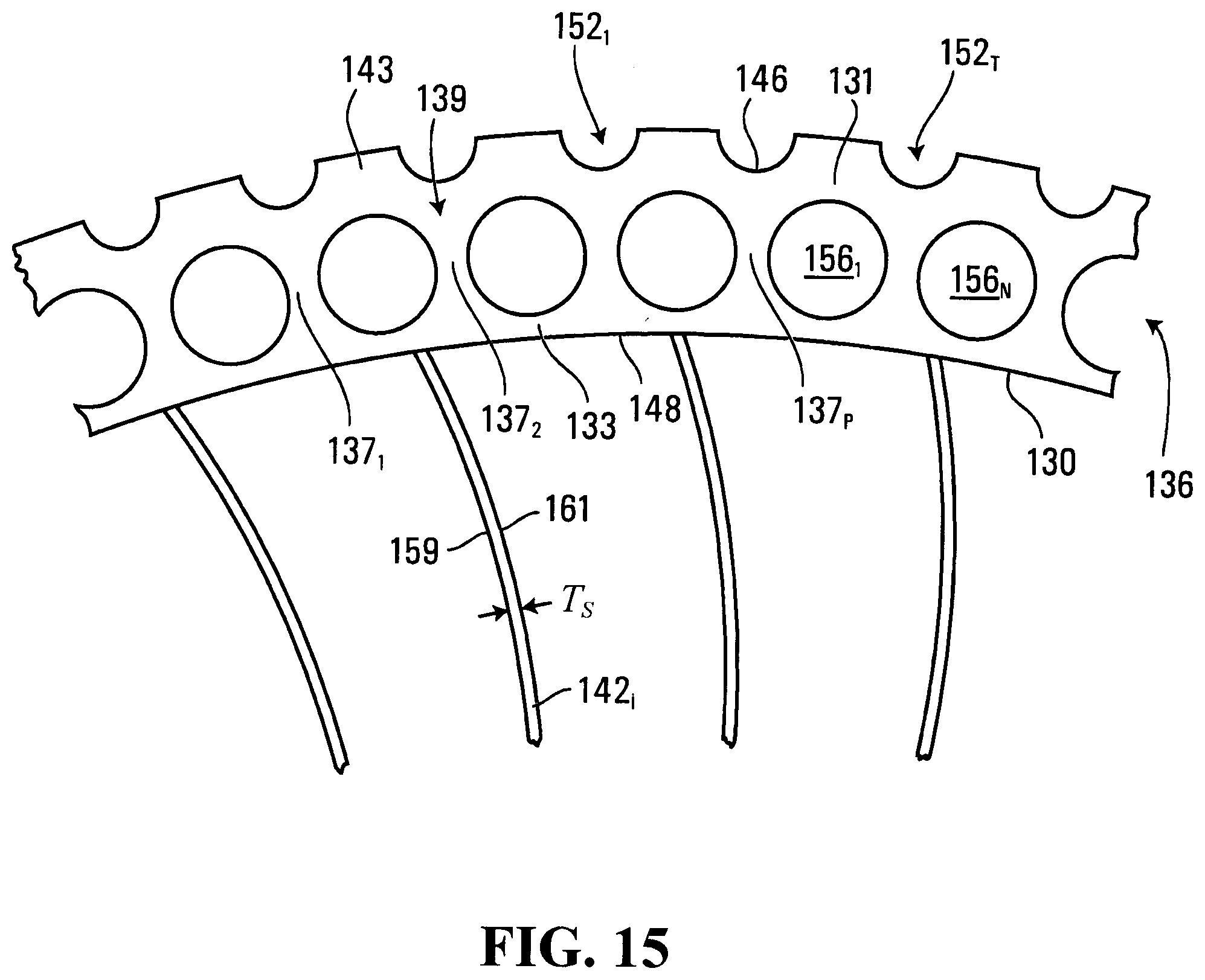
D00017

D00018

D00019
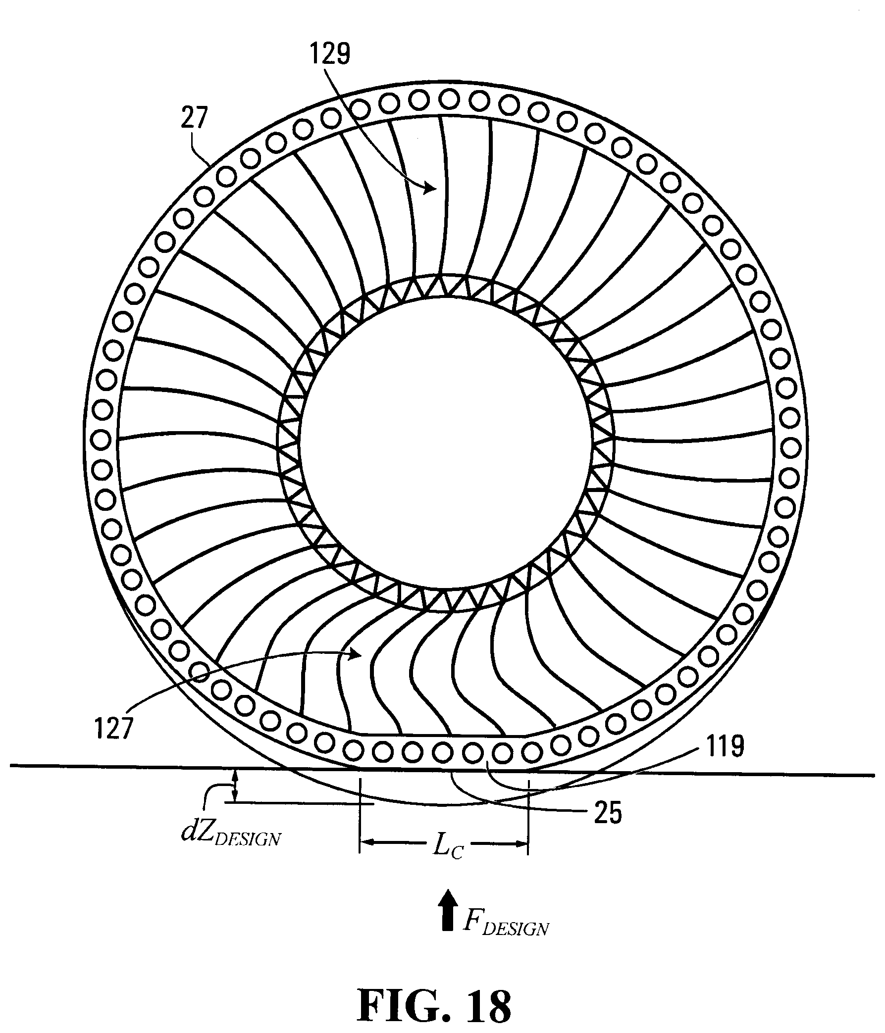
D00020

D00021

D00022
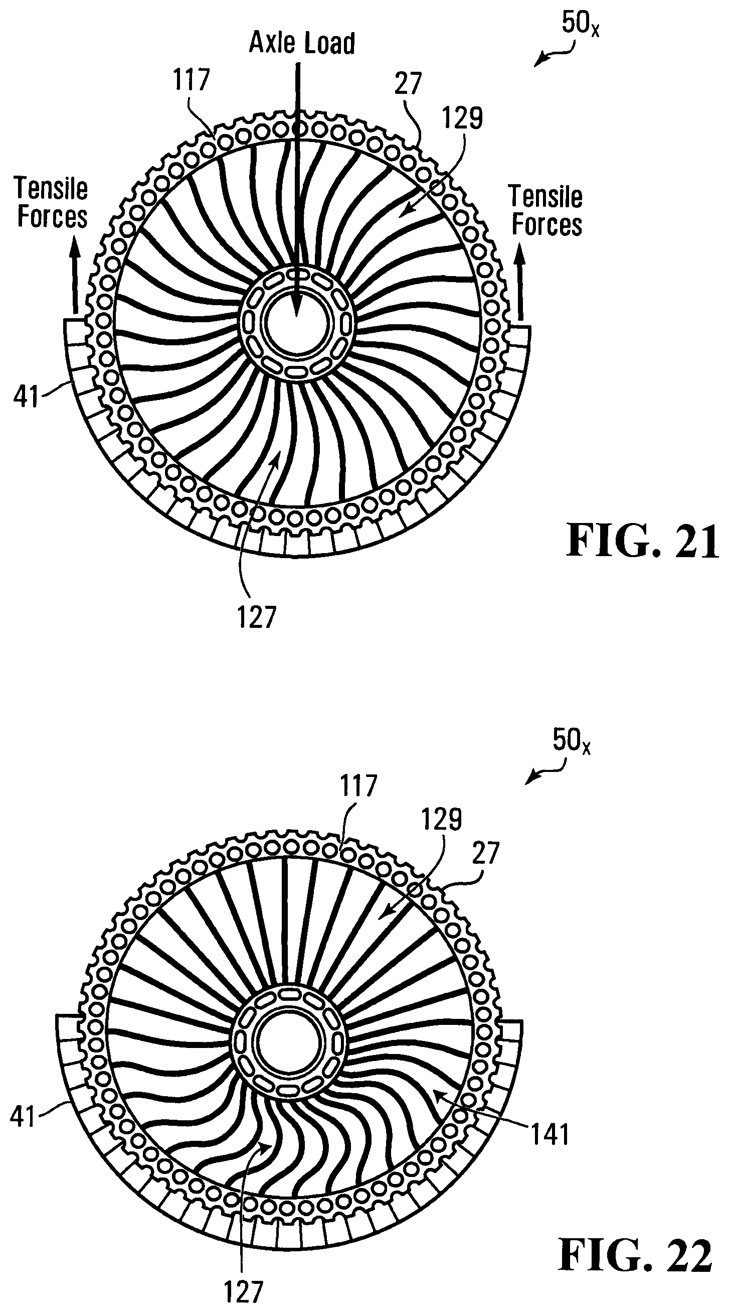
D00023
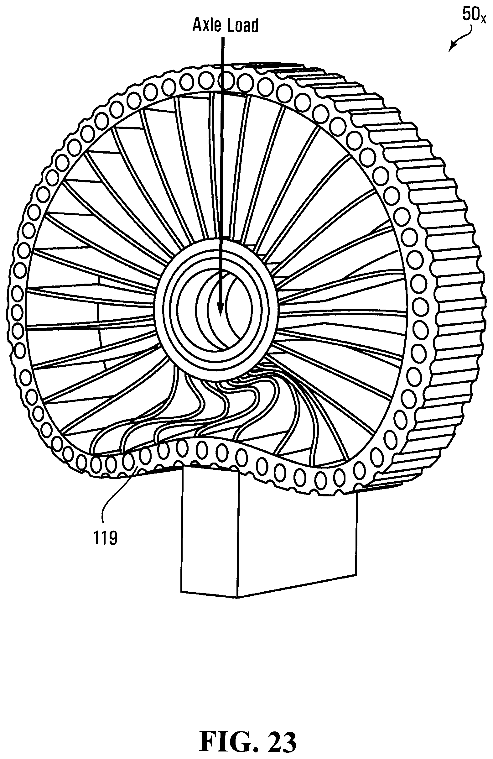
D00024
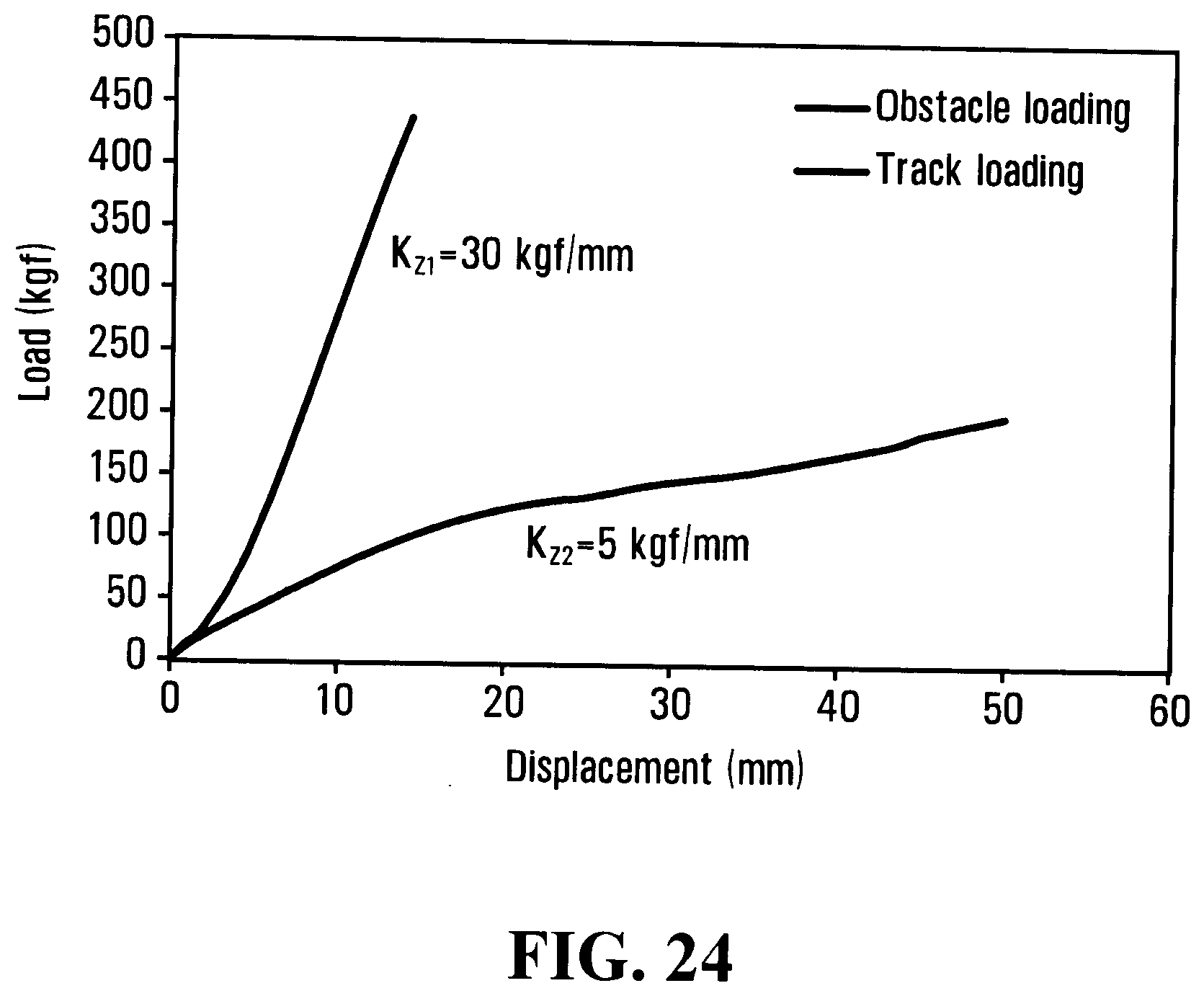
D00025

D00026
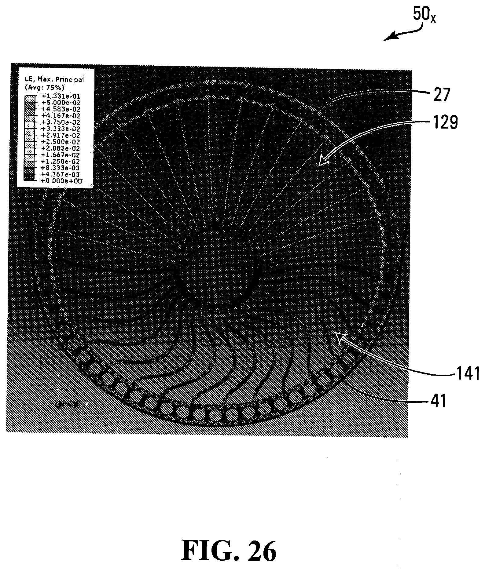
D00027

D00028

D00029
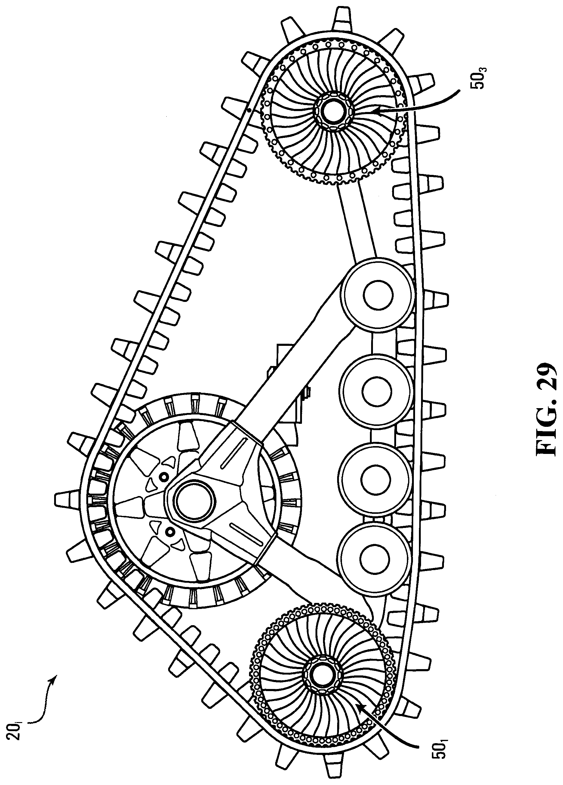
D00030

D00031

D00032

D00033
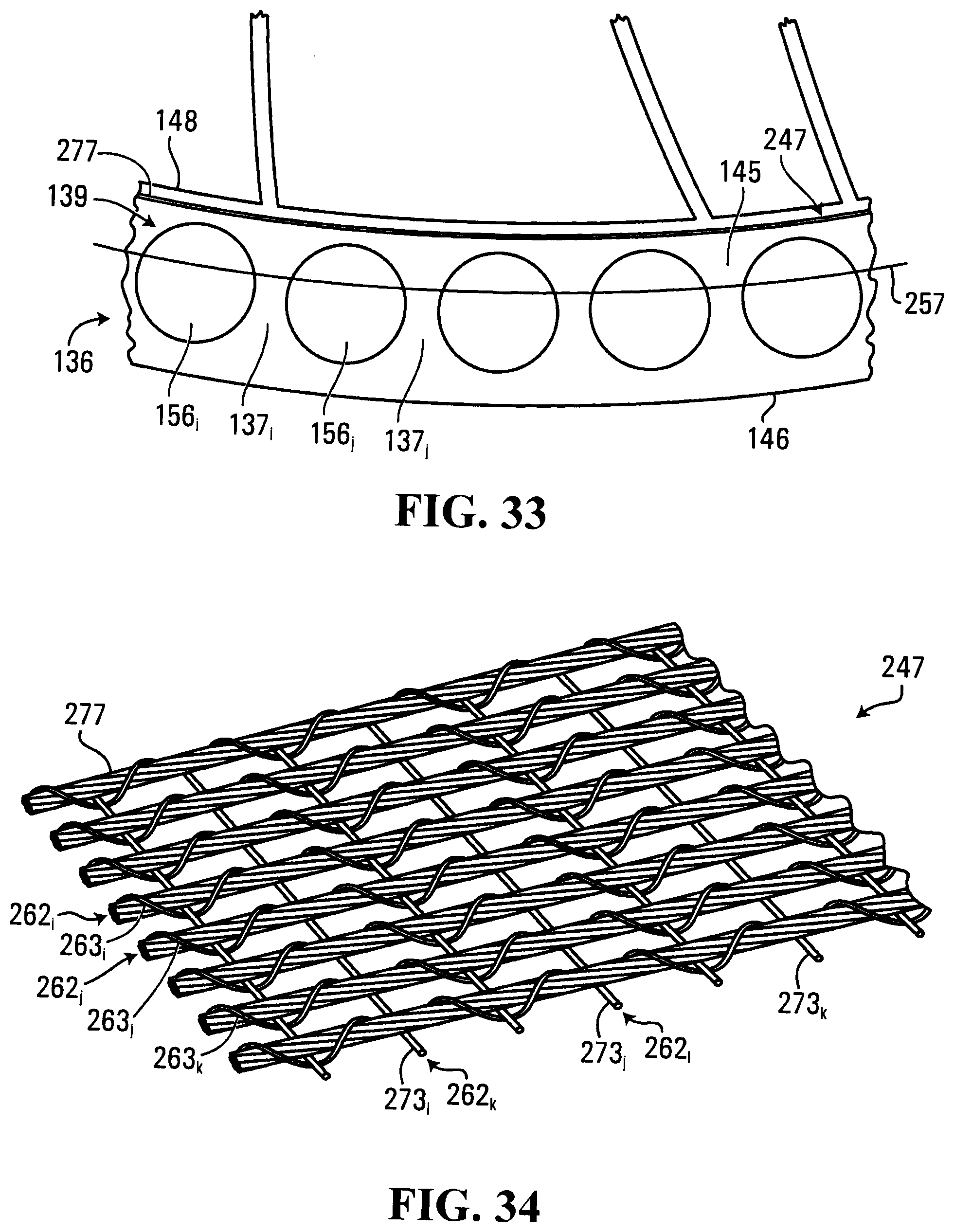
D00034

D00035

D00036

D00037
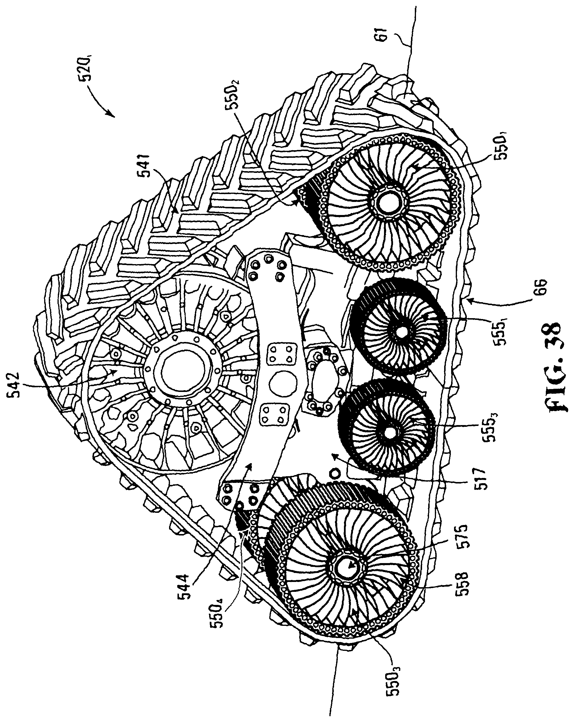


P00999

XML
uspto.report is an independent third-party trademark research tool that is not affiliated, endorsed, or sponsored by the United States Patent and Trademark Office (USPTO) or any other governmental organization. The information provided by uspto.report is based on publicly available data at the time of writing and is intended for informational purposes only.
While we strive to provide accurate and up-to-date information, we do not guarantee the accuracy, completeness, reliability, or suitability of the information displayed on this site. The use of this site is at your own risk. Any reliance you place on such information is therefore strictly at your own risk.
All official trademark data, including owner information, should be verified by visiting the official USPTO website at www.uspto.gov. This site is not intended to replace professional legal advice and should not be used as a substitute for consulting with a legal professional who is knowledgeable about trademark law.