Weight-Stabilized Beverage Container Flotation Device and Kit
MCCUTCHEN; James
U.S. patent application number 16/646300 was filed with the patent office on 2020-09-03 for weight-stabilized beverage container flotation device and kit. The applicant listed for this patent is James MCCUTCHEN. Invention is credited to James MCCUTCHEN.
| Application Number | 20200275792 16/646300 |
| Document ID | / |
| Family ID | 1000004854236 |
| Filed Date | 2020-09-03 |


View All Diagrams
| United States Patent Application | 20200275792 |
| Kind Code | A1 |
| MCCUTCHEN; James | September 3, 2020 |
Weight-Stabilized Beverage Container Flotation Device and Kit
Abstract
A floatation device for a beverage container is configured to have a displacement with a floatation buoyancy sufficient to float the floatation device both empty and while holding the beverage container, whether empty or filled. The floatation device may have a cup-shaped body, a buoyant member (either permanently attached or removably attachable to the cup-shaped body), and a weighting member, with a center of gravity of the floatation device being below a middle point between a base and a top portion of the floatation device. A kit may be provided with one or more cup-shaped bodies and one or more buoyant members to provide user selectability in view use with a container selected from a group of differently-sized containers.
| Inventors: | MCCUTCHEN; James; (Greer, SC) | ||||||||||
| Applicant: |
|
||||||||||
|---|---|---|---|---|---|---|---|---|---|---|---|
| Family ID: | 1000004854236 | ||||||||||
| Appl. No.: | 16/646300 | ||||||||||
| Filed: | September 7, 2018 | ||||||||||
| PCT Filed: | September 7, 2018 | ||||||||||
| PCT NO: | PCT/US2018/049846 | ||||||||||
| 371 Date: | March 11, 2020 |
Related U.S. Patent Documents
| Application Number | Filing Date | Patent Number | ||
|---|---|---|---|---|
| 62557490 | Sep 12, 2017 | |||
| 62625499 | Feb 2, 2018 | |||
| Current U.S. Class: | 1/1 |
| Current CPC Class: | A47G 2200/02 20130101; A47G 23/0216 20130101 |
| International Class: | A47G 23/02 20060101 A47G023/02 |
Claims
1. A floatation device for a beverage container comprising: a cup-shaped body for receiving the beverage container therein, the cup-shaped body having a base and a generally annular side wall having a bottom portion contacting the base; a weighting member located substantially at the base; a buoyant member shaped generally annular and removably attachable to the cup-shaped body spaced from the base, the cup-shaped body and the buoyant member defining a volume within the side wall between the base and a point substantially along a top portion of an inner wall of the buoyant member; and the cup-shaped body, the buoyant member, and the weighting member being collectively configured so as to have a displacement with a floatation buoyancy greater than a weight of water within the volume plus the weight of the cup-shaped body, the buoyant member, and the weighting member.
2-3. (canceled)
4. The floatation device for a beverage container of claim 1, wherein a weight of the weighting member is about 1.0 pound.
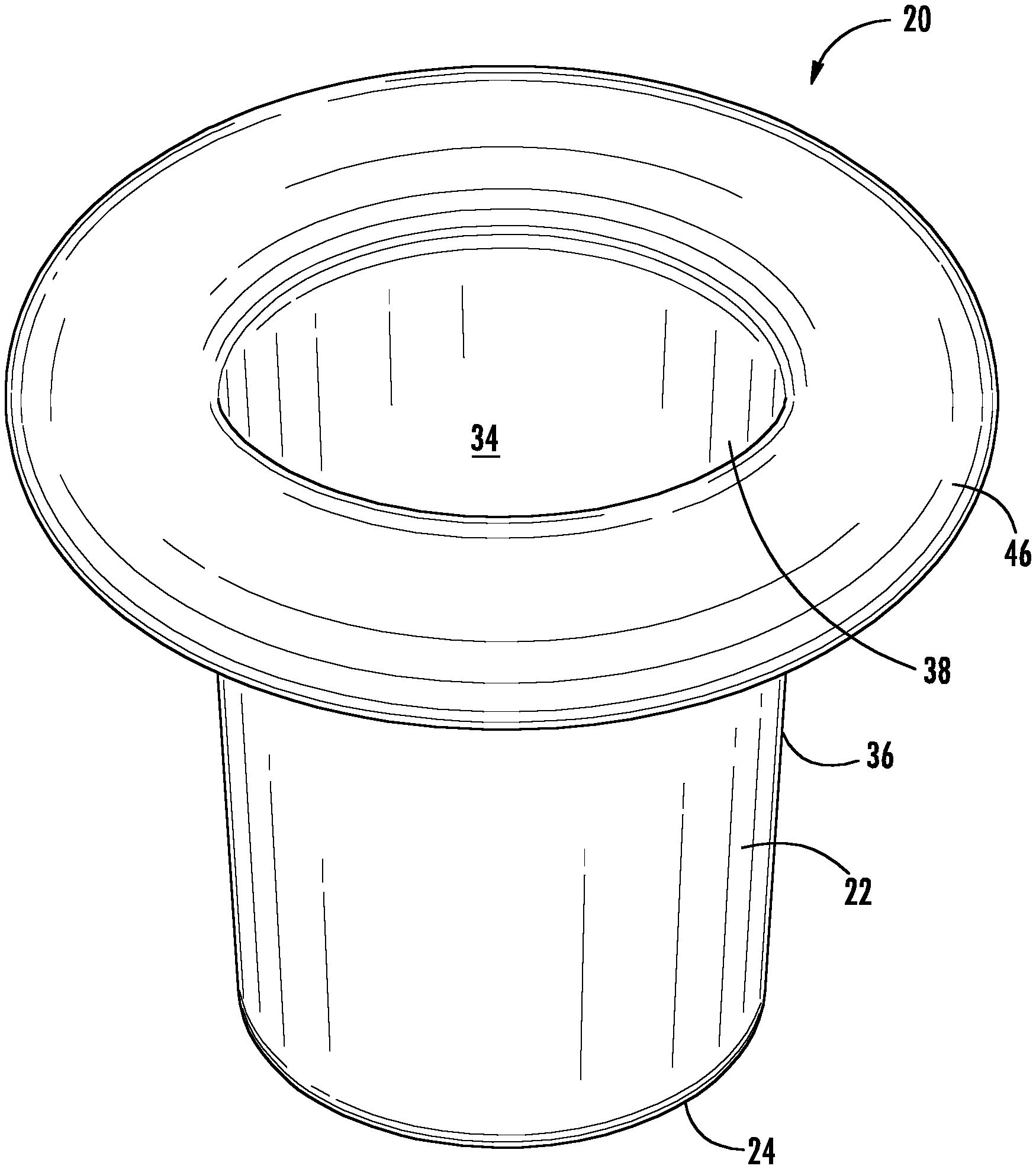
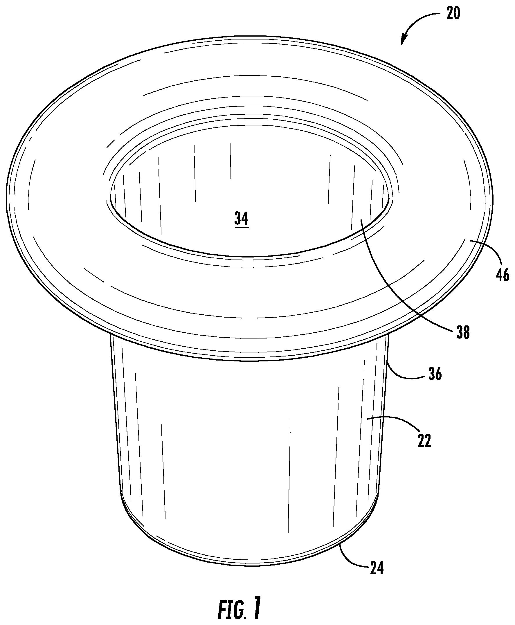
5. The floatation device for a beverage container of claim 1, wherein the floatation buoyancy is at least about 2.0 pounds.
6. The floatation device for a beverage container of claim 1, wherein the displacement while floating with the beverage container within the volume is at least about 60 in.sup.3.
7-10. (canceled)
11. The floatation device for a beverage container of claim 1, wherein a center of gravity of the floatation device is below a middle point between the base and the top portion.
12-13. (canceled)
14. The floatation device for a beverage container of claim 1, further including a snap-fit fastening assembly for attaching the buoyant member to the cup-shaped body.
15. The floatation device for a beverage container of claim 14, wherein the snap-fit fastening assembly includes interlocking tab members on the buoyant member and the cup-shaped body.
16. The floatation device for a beverage container of claim 1, further including a threaded fastening assembly for attaching the buoyant member to the cup-shaped body.
17. The floatation device for a beverage container of claim 16, wherein the threaded fastening assembly includes mating thread members on the buoyant member and the cup-shaped body.
18. The floatation device for a beverage container of claim 1, wherein an interior surface of the buoyant member is configured for receipt of the beverage container.
19-22. (canceled)
23. The floatation device for a beverage container of claim 18, wherein the interior surface includes at least one radially-inwardly extending protrusion for gripping the container.
24. The floatation device for a beverage container of claim 1, wherein the base of the cup-shaped body has a bottom support surface configured so that the floatation device can be placed on a surface without toppling.
25-33. (canceled)
34. A floatation device for a beverage container comprising: a cup-shaped body for receiving the beverage container therein, the cup-shaped body having a base and a generally annular side wall having a bottom portion contacting the base, a top portion spaced from the base, and a side portion between the bottom portion and the top portion, the cup-shaped body defining a volume within the side wall between the base and the top portion; a weighting member located substantially at the base; a buoyant member located substantially along the top portion; and the cup-shaped body, the buoyant member, and the weighting member being collectively configured so as to have a displacement with a floatation buoyancy greater than a weight of water within the volume plus the weight of the cup-shaped body, the buoyant member, and the weighting member.
35-36. (canceled)
37. The floatation device for a beverage container of claim 34, wherein a weight of the weighting member is about 1.0 pound.
38. The floatation device for a beverage container of claim 34, wherein the floatation buoyancy is at least about 2.0 pounds.
39. (canceled)
40. The floatation device for a beverage container of claim 34, wherein the displacement while floating with the beverage container within the volume is at least about 60 in.sup.3.
41. The floatation device for a beverage container of claim 34, wherein the displacement while floating with the beverage container within the volume is at least about 80 in.sup.3.
42-43. (canceled)
44. The floatation device for a beverage container of claim 34, wherein a center of gravity of the floatation device is below a middle point between the base and the top portion.
45-47. (canceled)
48. A floatation device for a beverage container comprising: a cup-shaped body for receiving the beverage container therein, the cup-shaped body having a base and a generally annular side wall having a bottom portion contacting the base, a top portion spaced from the base, and a side portion between the bottom portion and the top portion, the cup-shaped body defining a volume within the side wall between the base and the top portion; a weighting member located substantially at the base; a buoyant member located substantially along the top portion; and the cup-shaped body, the buoyant member, and the weighting member being collectively configured so that a center of gravity of the floatation device is below a middle point between the base and the top portion.
49-50. (canceled)
Description
CROSS-REFERENCE TO RELATED APPLICATIONS
[0001] The present application is a US Nationalization of International Application No. PCT/US2018/049846, filed Sep. 7, 2018 and claims priority to U.S. Provisional Patent Application Ser. Nos. 62/557,490, filed Sep. 12, 2017 and 62/625,499, filed Feb. 2, 2018, all of which are incorporated by reference herein.
TECHNICAL FIELD
[0002] The present disclosure relates to a device capable of buoyantly supporting a beverage container in a stable manner.
BACKGROUND
[0003] Beverage insulating devices, sometimes called "cozies" or "koozies," have been proposed for maintaining the temperature of beverage containers and the beverages contained therein. Such devices are typically cup-shaped, with a circular base and an annular wall configured for receiving a common 12 ounce beverage can. Such devices typically have a small hole in the bottom for condensation drainage and to allow for pushing a container out of the device. Other such devices are annular, fitting only around the side of a can but not along the bottom. Still other devices are rectangular and can be wrapped around a can with ends secured together, for example, by a hook and loop fastener. Existing devices are made of an insulating material of some sort, thereby maintaining a cooled beverage at a lower temperature than if exposed to environment, and also making the cooled beverage container more comfortable to hold.
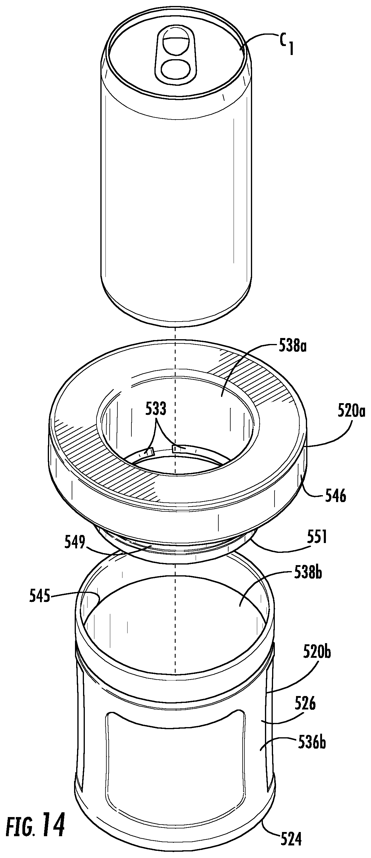
[0004] Existing beverage insulating devices generally serve their desired purpose of maintaining the temperature of a beverage and/or providing a thermally more comfortable gripping surface for the user. However, existing beverage insulating devices are not of sufficient shape and/or buoyancy to be able to float freely in a water environment such as a pool, lake, tub, etc. With existing beverage insulating devices, once left to float on the surface of the water environment, the beverage insulating device and container will topple, thereby potentially spilling the beverage into the water environment and/or allowing an undesired level of heat transfer to or from the beverage container due to direct contact with water environment.
[0005] Accordingly, improvements in insulated beverage cooling devices that reliably float on the surface of a water environment and/or addressing one or more drawbacks of existing devices or other issues would be welcome.
SUMMARY
[0006] According to certain aspects of the disclosure, a floatation device for a beverage container may include a cup-shaped body for receiving the beverage container therein. The cup-shaped body has a base and a generally annular side wall having a bottom portion contacting the base, a top portion spaced from the base, and a side portion between the bottom portion and the top portion. The cup-shaped body defines a volume within the side wall between the base and the top portion. A weighting member is located substantially at the base. A buoyant member is located substantially along the top portion. The cup-shaped body, the buoyant member, and the weighting member are collectively configured so as to have a displacement with a floatation buoyancy greater than a weight of water within the volume plus the weight of the cup-shaped body, the buoyant member, and the weighting member. Various options and modifications are possible.
[0007] According to certain other aspects of the disclosure, a floatation device for a beverage container may include a cup-shaped body for receiving the beverage container therein. The cup-shaped body has a base and a generally annular side wall having a bottom portion contacting the base, a top portion spaced from the base, and a side portion between the bottom portion and the top portion. The cup-shaped body defines a volume within the side wall between the base and the top portion. A weighting member is located substantially at the base. A buoyant member is located substantially along the top portion. The cup-shaped body, the buoyant member, and the weighting member are collectively configured to have a displacement with a floatation buoyancy sufficient to float the floatation device both while empty and with the beverage container within the volume. Various options and modifications are possible.
[0008] According to another aspect of the disclosure, a floatation device for a beverage container may include a cup-shaped body for receiving the beverage container therein. The cup-shaped body has a base and a generally annular side wall having a bottom portion contacting the base, a top portion spaced from the base, and a side portion between the bottom portion and the top portion. The cup-shaped body defines a volume within the side wall between the base and the top portion. A weighting member is located substantially at the base. A buoyant member is located substantially along the top portion. The cup-shaped body, the buoyant member, and the weighting member are collectively configured so that a center of gravity of the floatation device is below a middle point between the base and the top portion. Various options and modifications are possible.
[0009] According to certain other aspects of the disclosure, a floatation device for a beverage container may include a cup-shaped body for receiving the beverage container therein. The cup-shaped body has a base and a generally annular side wall having a bottom portion contacting the base. A weighting member is located substantially at the base. A buoyant member is shaped generally annular and is removably attachable to the cup-shaped body spaced from the base. The cup-shaped body and the buoyant member define a volume within the side wall between the base and a point substantially along a top portion of an inner wall of the buoyant member. The cup-shaped body, the buoyant member, and the weighting member are collectively configured so as to have a displacement with a floatation buoyancy greater than a weight of water within the volume plus the weight of the cup-shaped body, the buoyant member, and the weighting member. Various options and modifications are possible.
[0010] According to certain other aspects of the disclosure, a floatation device for a beverage container may include a cup-shaped body for receiving the beverage container therein. The cup-shaped body has a base and a generally annular side wall having a bottom portion contacting the base. A weighting member is located substantially at the base. A buoyant member is shaped generally annular and is removably attachable to the cup-shaped body spaced from the base. The cup-shaped body and the buoyant member define a volume within the side wall between the base and a point substantially along a top portion of an inner wall of the buoyant member. The cup-shaped body, the buoyant member, and the weighting member are collectively configured to have a displacement with a floatation buoyancy sufficient to float the floatation device both while empty and with the beverage container within the volume. Various options and modifications are possible.
[0011] A floatation device for a beverage container may include a cup-shaped body for receiving the beverage container therein. The cup-shaped body has a base and a generally annular side wall having a bottom portion contacting the base. A weighting member is located substantially at the base. A buoyant member is shaped generally annular and is removably attachable to the cup-shaped body spaced from the base. The cup-shaped body and the buoyant member define a volume within the side wall between the base and a point substantially along a top portion of an inner wall of the buoyant member. The cup-shaped body, the buoyant member, and the weighting member are collectively configured so that a center of gravity of the floatation device is below a middle point between the base and the top portion. Various options and modifications are possible.
[0012] According to other aspects of the disclosure, a kit may be provided including at least one of cup shaped body and at least one of buoyant member, according to this disclosure. If so, the kit may include at least one cup shaped body and a plurality of the buoyant members, each of the plurality of the buoyant members having a different inner surface configuration. Various options and modifications are available with the kit.
BRIEF DESCRIPTION OF THE DRAWINGS
[0013] More details of the present disclosure are set forth in the drawings.
[0014] FIG. 1 is an isometric view of a beverage container floatation device according to a first embodiment, with a substantially circular (from above) and substantially round (in vertical cross-section) float portion.
[0015] FIG. 2 is a side view thereof (the view from any side being identical).
[0016] FIG. 3 is an isometric view thereof showing how a beverage container would fit in the beverage container floatation device of FIG. 1.
[0017] FIG. 4 is a cross-sectional view of the beverage container floatation device of FIG. 1.
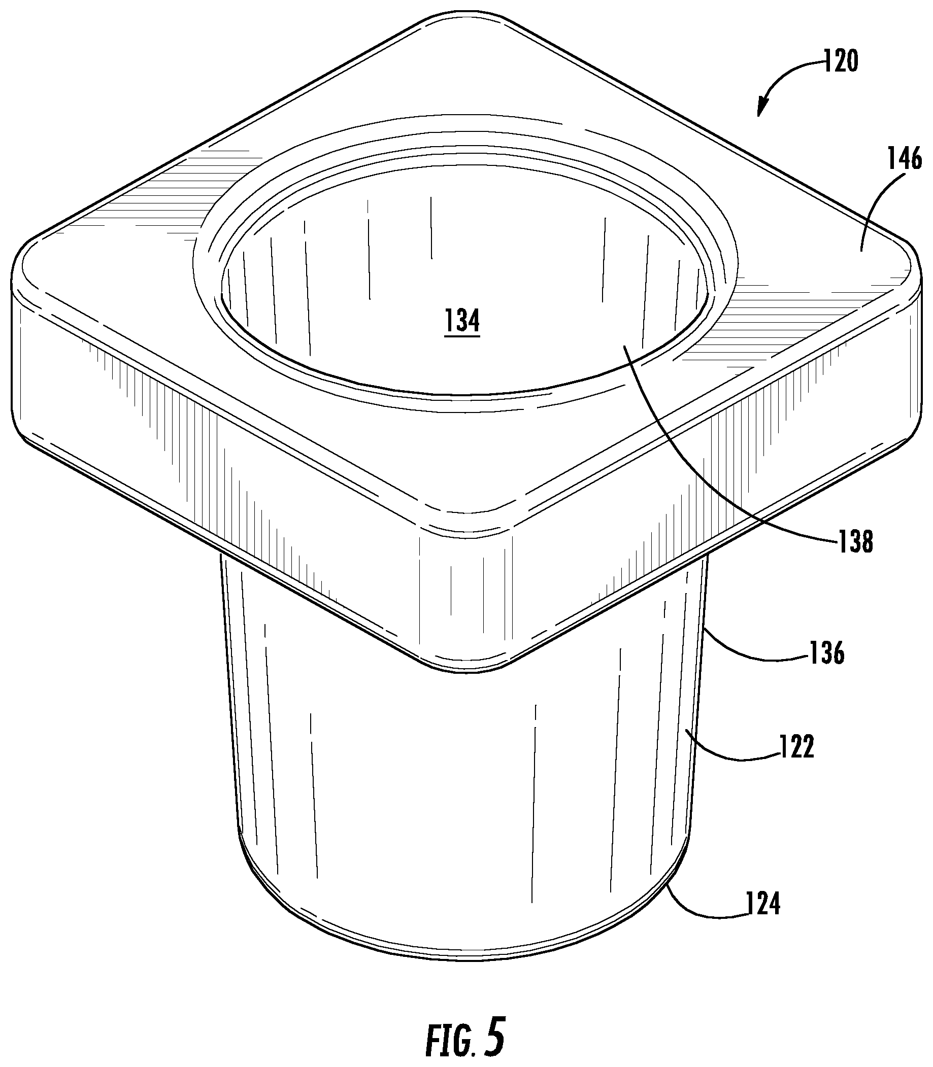
[0018] FIG. 5 is an isometric view of a beverage container floatation device according to a second embodiment, with a substantially square (from above) and substantially rectangular (in vertical cross-section) float portion.
[0019] FIG. 6 is a cross-sectional view of the beverage container floatation device of FIG. 5.
[0020] FIG. 7 is an isometric view of a beverage container floatation device according to a third embodiment, with a substantially circular (from above) and substantially round (in vertical cross-section) float portion sized differently than in the embodiment of FIG. 1.
[0021] FIG. 8 is a cross-sectional view of the beverage container floatation device of FIG. 7.
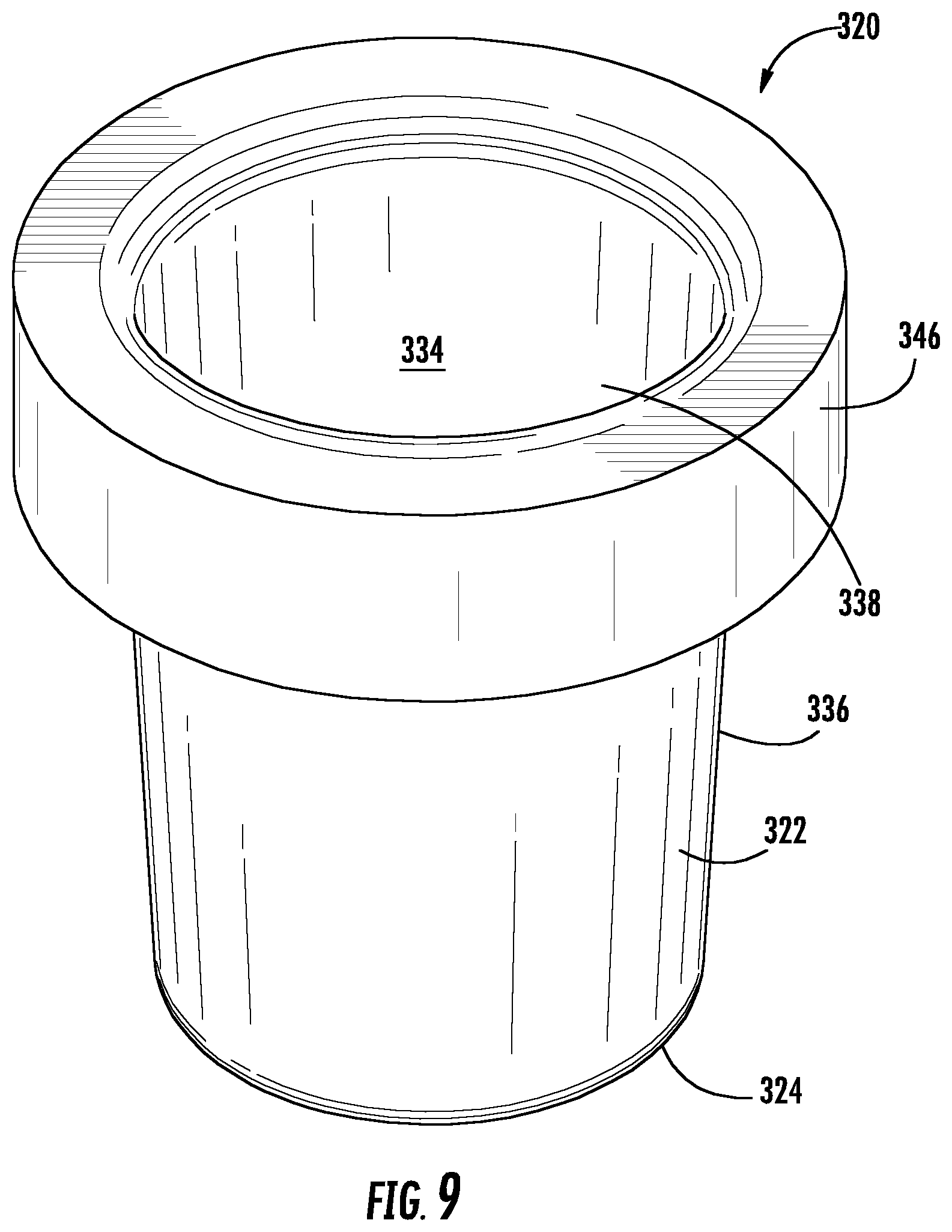
[0022] FIG. 9 is an isometric view of a beverage container floatation device according to a fourth embodiment, with a substantially round (from above) and substantially rectangular (in vertical cross-section) float portion.
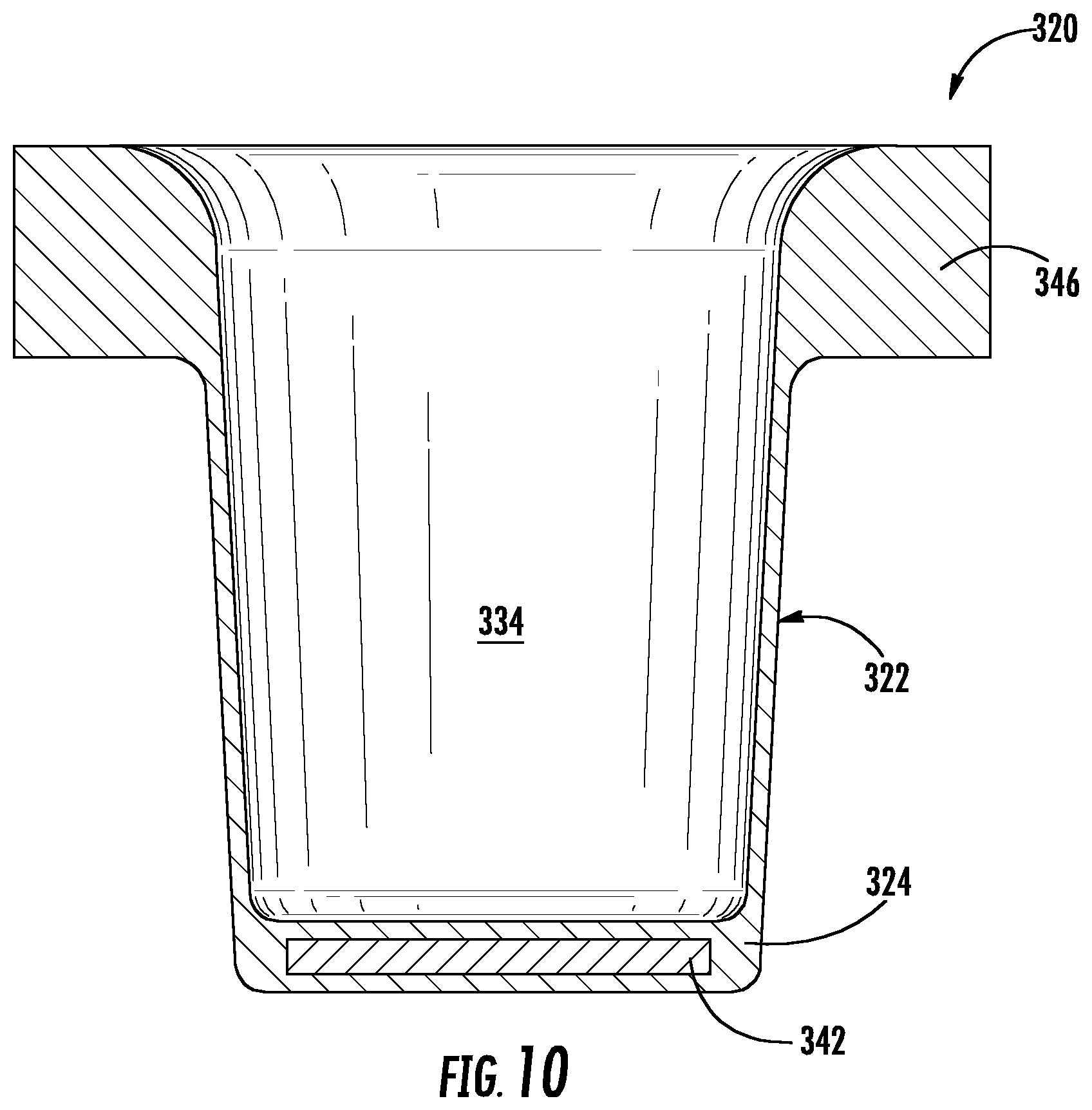
[0023] FIG. 10 is a cross-sectional view of the beverage container floatation device of FIG. 9
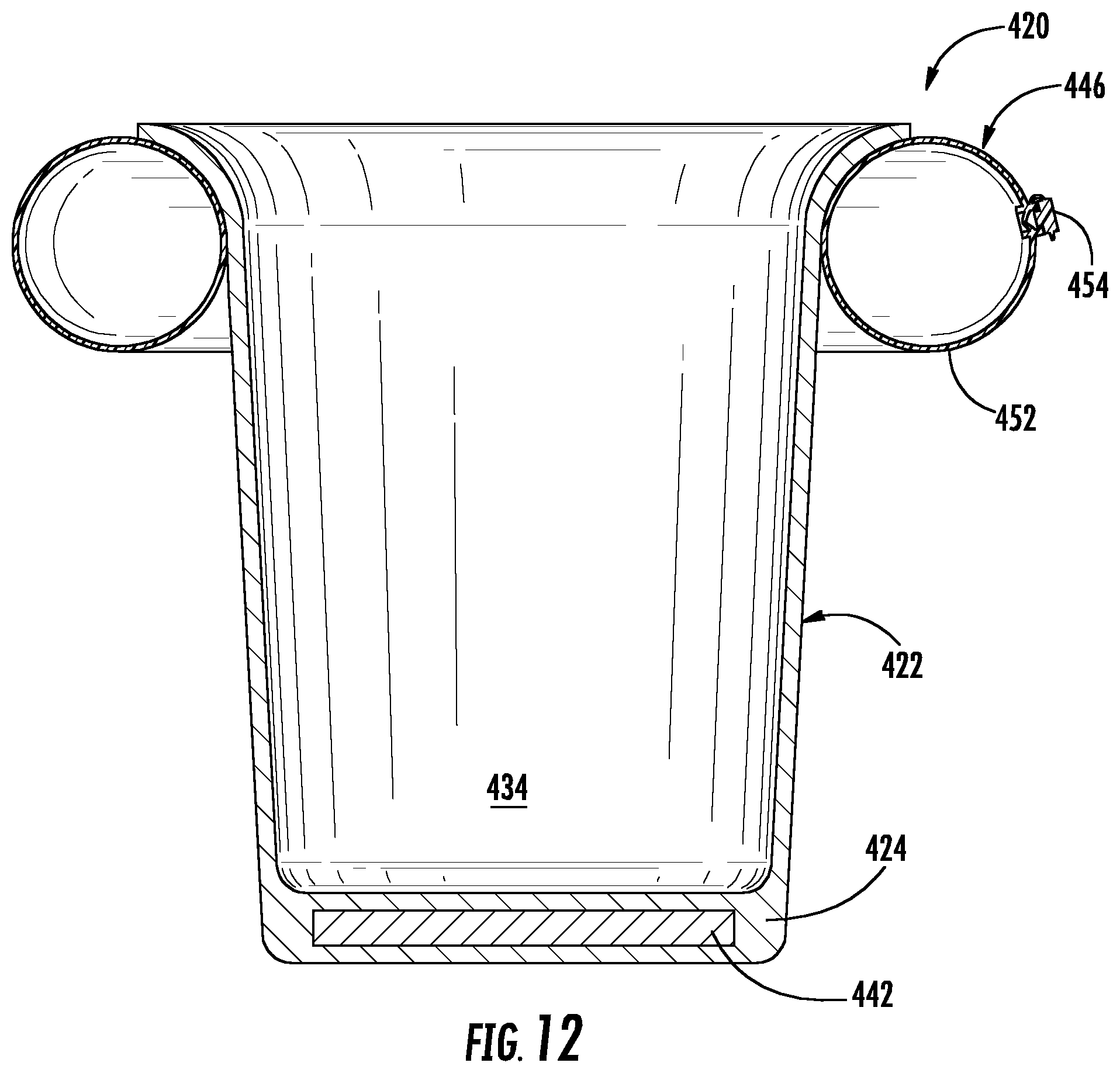
[0024] FIG. 11 is an isometric view of a beverage container floatation device according to a fifth embodiment, with a substantially round (from above) and substantially round (in vertical cross-section) and inflatable float portion.
[0025] FIG. 12 is a cross-sectional view of the beverage container floatation device of FIG. 11.
[0026] FIG. 13 is an isometric view of a beverage container floatation device according to a sixth embodiment, formed as a two-part device, holding a container (i.e., a can) therein.
[0027] FIG. 14 is an exploded isometric view of the device of FIG. 13.
[0028] FIG. 15 is a close-up isometric view of the top portion of the device of FIG. 13.
[0029] FIG. 16 is a side view of the top portion of the device of FIG. 13.
[0030] FIG. 17 is a top view of the top portion of the device of FIG. 13.
[0031] FIG. 18 is a cross-sectional view of the device of FIG. 13.
[0032] FIG. 19 is a cross sectional view of a modified version of the device of FIG. 13, holding a container (i.e., a tumbler) therein.
DETAILED DESCRIPTION
[0033] Detailed reference will now be made to the drawings in which examples embodying the present disclosure are shown. The detailed description uses numeral and letter designations to refer to features in the drawings. Like or similar designations in the drawings and description have been used to refer to like or similar parts of the disclosure.
[0034] The drawings and detailed description provide a full and enabling description of the disclosure and the manner and process of making and using it. Each embodiment is provided by way of explanation of the subject matter not limitation thereof. In fact, it will be apparent to those skilled in the art that various modifications and variations may be made to the disclosed subject matter without departing from the scope or spirit of the disclosure. For instance, features illustrated or described as part of one embodiment may be used with another embodiment to yield a still further embodiment.
[0035] Generally speaking, FIGS. 1-19 depict examples of floatation devices for beverage containers. It should be understood that the embodiments shown in FIGS. 1-19 are simply examples, and that many options and modifications may be employed, all still within the scope of the present invention. For example, the devices may be made in differing shapes and differing sizes to conform to currently available or future designs of beverage containers. The devices may, but need not, be tightly form-fitting around the beverage containers, as a range of sizes of and configurations of the containers may be used with each embodiment. The floatation devices may be configured for ready insertion and removal of beverage containers from the devices. The floatation devices may be configured for stable floating on a water environment, whether empty, whether holding an empty beverage container, or whether holding a filled beverage container. The floatation devices may be weighted to ensure upright orientation while floating and to assist in holding the devices and beverage containers upright while placed on a non-liquid surface. The floatation devices may also have a substantially flat bottom shape so that they may be stably placed on a hard surface (such as a table) without toppling. The floatation devices may have space for indicia (printed, attached, molded, etc.) along various surfaces thereof. The floatation devices may also be shaped or made of materials so that they are at least partially axially nestable so as be efficiently stored after manufacture, during shipment or sale, or during home storage by a consumer. It should also be understood that the numerical examples discussed herein are intended to set forth certain examples and concepts, and particular numerical examples are not themselves meant to be limiting as to the scope of the invention.
[0036] Also, the floatation devices may be formed in one part, or in two parts, or in more than two parts. Aspects of the multi-part embodiments of FIGS. 13-19 may be used with aspects of the embodiments of FIGS. 1-12, and vice-versa, to arrive at still further embodiments.
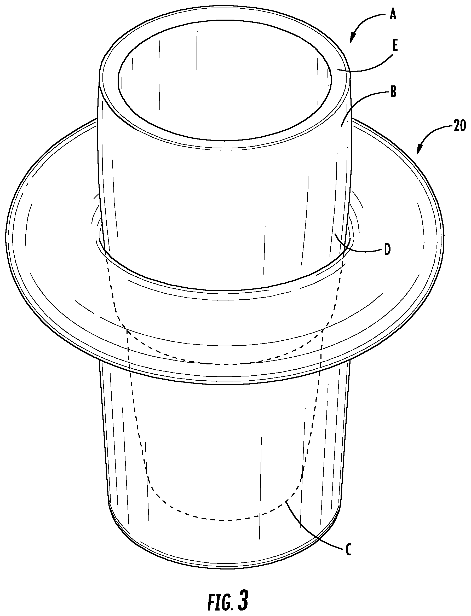
[0037] FIGS. 1-4 show a first embodiment of a floatation device 20 for a beverage container A. The beverage container A may include a cup-shaped body B having a base C and a side wall D, which may be axially symmetrical (as shown) or which vary along the height from base C to top E. As illustrated, cup-shaped body B of beverage container A is a 32 oz. tumbler-sized cup. Beverage container A may include an optional cover of various conventional designs (not shown) to removably close top E.
[0038] For example, the cover may be passive and removable for drinking, or it may have a hole for drinking and may also include at least one vent hole for venting air into the cup-shaped body while drinking to relieve carbonation build up. A manually movable cap may be slid or pivoted to open a drinking and/or venting hole in the cover. A straw or other device may be removably or permanently attached to the cover. Alternately, the cover may include active elements such as conventional suction-operated valving, push-button operated valving, etc., to allow drinking and/or venting.
[0039] Cup-shaped body B may be made of various conventional materials, such as plastics, metals, insulating materials, either individually or in layers. Thus beverage container A may be of any conventional cup size, from a small size such as 6 or 8 oz., to 12-16 oz., to bigger "tumbler" sizes such as 20 oz., 32 oz. or larger. The cup-shaped body B may itself be insulated or uninsulated. It should thus be understood that certain aspects of the floatation device provide benefits that apply regardless of the size, configuration, weight, and/or buoyancy of beverage container that might be used with the floatation device. However, certain aspects of the floatation device provide stability benefits to larger beverage containers. The present invention is dictated by the disclosure as a whole and the appended claims. Accordingly, it should be understood that the disclosure is not limited to use with a beverage container or with any particular beverage container.
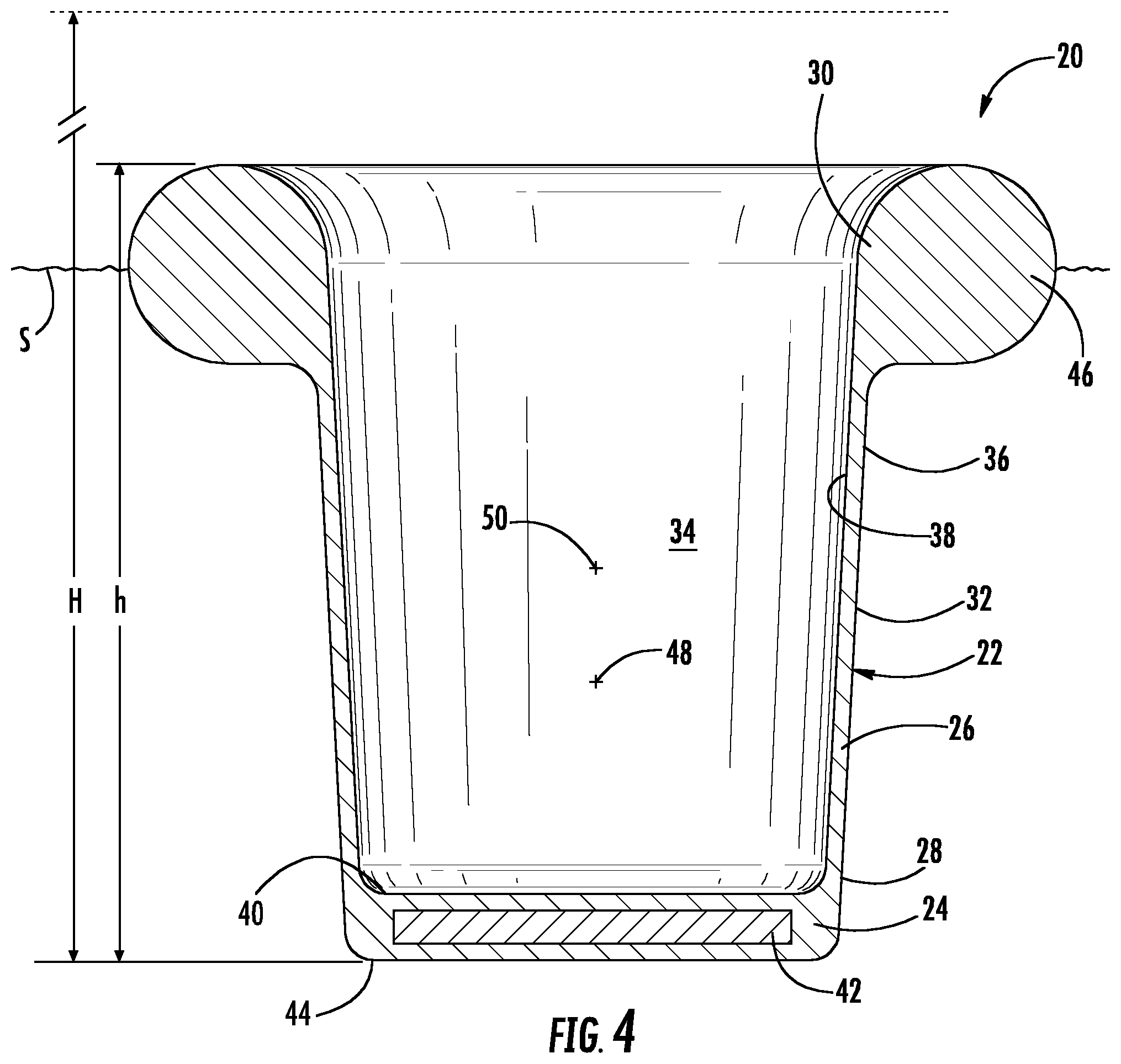
[0040] As illustrated, device 20 includes a cup-shaped body 22 for receiving the beverage container A therein. Cup-shaped body 22 has a base 24 and a generally annular side wall 26 having a bottom portion 28 contacting the base, a top portion 30 spaced from the base, and a side portion 32 between the bottom portion and the top portion. Cup-shaped body 22 defines a volume 34 within side wall 26 between base 24 and top portion 30.
[0041] Side wall 26 of cup-shaped body 22 may be uniform in thickness from bottom portion 28 to top portion 30, or it may taper regularly, irregularly, in steps, etc., or it may vary in an irregular fashion. Any such variation in thickness of side wall 26 may be made by varying one or both of outer surface 36 or inner surface 38 of the side wall. Volume 34 (defined specifically by inner surface 38 of side wall 26, top surface 40 of bottom portion 28, and a top portion 30) may be generally cylindrical, frusto-conical, or other shapes. Inner surface 38 and volume 34 may thus be sized to snugly fit a given side wall D of beverage container A, either with or without stretching. Alternatively, inner surface 38 and volume 34 may simply be large enough to hold beverage container A therein, without snugly gripping some or all of side wall D. However, it is believed that increasing contact between floatation device 20 and beverage container A does promote thermal insulation of the beverage container and any beverage held therein, as well as preventing intrusion of environmental water into volume 34. In particular, contact between at least some if not all of the top portion 30 circumferentially around side wall D improves such insulation and reduces or precludes such environmental water intrusion. In view of the above, it should be understood that cup-shaped body 22, side wall 26, and accordingly volume 34 may all depart from that illustrated in numerous ways within the scope of the invention.
[0042] At least one weighting member 42 may be located substantially at base 24. As shown, weighting member 42 may be disc-shaped and may have a density higher than that of cup-shaped body 22. Weighting member 42 has a weight and density selected to balance out buoyancy and weight forces, as will be described below.
[0043] Weighting member 42 may be overmolded in place, as illustrated, or may be slid into a slot or opening in base 24. Alternatively, weighting member 42 may be attached to an outer surface of cup-shaped body 22 near or on base 24, such as to top surface 40 or bottom surface 44 of base. If attached, weighting member 42 may be secured by a snap fit, weld, adhesive, tape, fastener, or other connecting structure, and cup-shaped body 22 may be modified accordingly.
[0044] The at least one weighting member 42 may also comprise separate weighting members (not shown). The separate members may have identical or differing weights for selectively balancing out forces, either with respect to a given floatation device design or with respect to a family of floatation devices of differing sizes. For example, if a floatation device of a larger size and/or for a larger beverage container A is envisioned, then more than one weighting members may be employed; whereas if a smaller device/container is envisioned, fewer or only one weighting member might be employed.
[0045] In the embodiment of FIGS. 1-4 (and in corresponding parts of later embodiments as well), bottom surface 44 may be configured as a bottom support surface wherein, filled or empty, device 20 can be placed on another surface without toppling. Thus, bottom surface may be substantially linear, may have one or more substantially horizontally-aligned portions, may have a substantially flat annular outer rim, etc., so that device 20 can be steadily and conveniently placed down on the ground, a table, or other surface.
[0046] At least one buoyant member 46 is located substantially along top portion 30 of side wall 26. Buoyant member 46 may be a substantially circular ring about cup-shaped body 22, having a substantially circular vertical cross-section (see FIG. 4). Buoyant member 46 is employed, as will be discussed below, to change the buoyancy and displacement of floatation device 20.
[0047] If desired, buoyant member 46 may be molded unitarily with cup-shaped body 22, as illustrated. However, buoyant member 46 may be formed separately from cup-shaped body 22 and then attached, for example, by a snap fit, weld, adhesive, tape, fastener, or other connecting structure, and cup-shaped body 22 may be modified accordingly.
[0048] Generally speaking, the parameters (size, shape, displacement, weight, buoyancy, etc.) of the various components above are selected so that flotation device 20 may hold a beverage container of small to large size and float while doing so, whether the container is empty, full, or anywhere in between. Thus, it is important, over a range of possible sizes, shapes, and weights of beverage containers to balance the flotation (buoyancy) required to float the container when full with the ballast required to keep the container floating upright when empty. Also, the present disclosure may generally achieve the combination of flotation and ballast in a manner that can be used in or out of the water, while still being aesthetically and ergonomically pleasing. The present design concepts may also allow for use of the floatation product in marketing and advertising to enhance the sales potential, for example by providing for indicia, labeling, etc., on the device.
[0049] One (non-exclusive) way to describe a relationship between the buoyancy, weight, configuration, etc., is to note that cup-shaped body 22, buoyant member 46, and weighting member 42 may be collectively configured so as to have a displacement in water with a floatation buoyancy greater than a weight of water within volume 34 plus the weight of cup-shaped body 22, buoyant member 46, and weighting member 42. In other words, if one were to fill volume 34 with water and place floatation device 20 on the surface S of a liquid environment, floatation device 20 would float. Due to the distribution of weight (density variations) between buoyant member 46 at top portion 30 and weighting member 42 at base 24, cup-shaped body would remain upright and not topple over, not substantially spill out water within volume. In this discussion, filling volume 34 with water is a proxy for weighing down device 20 with a beverage container A of some size and fullness level, but it makes the point that floatation and upright stability is desired.
[0050] Alternately, another (non-exclusive) way to describe a relationship between the buoyancy, weight, configuration, etc., is to note that a ratio of the height of the buoyant member above the base to a height of the beverage container. The ratio may be at least about 1/2, or even at least about 2/3, or even at least about 3/4. That is, a height h of the floatation device 20 should be at least about half if not at least about three-quarters the height H of beverage container A. In this way, buoyant member is located upwardly on beverage container A and helps hold the beverage container upright without toppling while floating. Such location, either separate from or together with the location of weighting member 42 at base 24, helps stabilize floatation device 20 while floating with a beverage container therein.
[0051] Still another (non-exclusive) relationship between parts is to note that a center of gravity 48 of floatation device 20 may be below a middle point 50 between base 24 and top portion 30. Without use of weighting member 42 in floatation device 20 if configured as shown, center of gravity 48 would be above middle point 50. When combined with the buoyancy and displacement of floatation device 20, a floating beverage container A might not be stable and might topple. Also, the center of gravity of floatation device 20 with beverage container A within volume 34 (whether filled with a liquid and/or ice, or whether empty) would still be below middle point 50.
[0052] Another (non-exclusive) relationship between the parts is that cup-shaped body 22, buoyant member 46, and weighting member 42 may be collectively configured to have a displacement with a floatation buoyancy sufficient to float floatation device 20 both empty and with beverage container A (itself full or empty) within volume 34. Thus, the matter making up the weight of floatation device 20 is distributed (i.e., it creates a displacement) such that floatation device 20 will float, even when a full beverage container A is placed therein.
[0053] To achieve such buoyancy, floatation device 20 or at least body portion 22 may be made of materials such as rubber, neoprene, foam, plastic, or other materials. For example, it may be desirable that the material have the ability to stretch and conform to different shapes of beverage containers, be comfortable to hold, not deteriorate due to being placed in and out of water, and provide a surface that can easily be printed with branding, advertising, etc. If desired, buoyant member 46 may be made of the same or similar material. However, it may also be made of a relatively more buoyant material such as a closed cell foam that will not absorb water, provides excellent flotation and adds very little weight overall to floatation device 20. If different materials are used, they may be overmolded or attached after creation.
[0054] By way of example, typical "tumbler" sized beverage containers come in smaller sizes (holding around 16-22 oz.) and larger sizes (holding around 28-32 oz). An example of parameters selected for a 20 oz. beverage container A (purchased Yeti.RTM. brand tumbler) is set forth below. Similar calculations can be made by one skilled in the art for beverage containers of other sizes using the principles above and the calculations below as a guide.
[0055] Weight of empty container (A)=12.4 oz.
[0056] Weight of container (A) full of water=28.8 oz.
[0057] Weight of metal discs used as weighting members (42)=16.0 oz.
[0058] Full container plus weighting members=44.8 oz.
[0059] Thus, with small added weight of a few ounces for rest of floatation device 20 and extra safety factor, assume total weight to be supported is at least about 48.0 oz. (3.0 lbs.), and same amount of buoyant force would be desired.
[0060] As buoyancy is a force equal to the weight of the volume displaced, a calculation of size of floatation device 20 can be made. A rubber, substantially cylindrical cup-shaped body 22 is utilized that is 4.0 in. in outer diameter and 4.0 in. tall between bottom of base 24 and top portion 30.
[0061] Water has a unit weight of 0.0361 lbs./in..sup.3 or 0.065 lbs./oz. Therefore, 3.0 lbs. of weight would require approximately 83 in.sup.3 of water volume displacement to provide the required buoyancy. The 4.0 in. diameter.times.4.0 in. height cup-shaped body 22 has a volume of V=.pi.r.sup.2h=.pi.*2.sup.2*4=approximately 50 in.sup.3. Accordingly, an additional displacement volume of approximately 33 in.sup.3 is needed to provide the required buoyancy. This additional buoyancy can be found in the additional volume of the beverage container A below the water surface, as well as the buoyant member 46 attached to the cup-shaped body.
[0062] At a 4.0 in. height, the diameter of the tested container is 3.5 in. For every additional 0.1 in. of height, an increase of about 1.0 in..sup.3 of volume will be present. Assuming the beverage container will add about 10 in..sup.3 of volume, the buoyant member would need to add about 23 in..sup.3 of volume to provide the required buoyancy. Using a buoyant member 46 that is circular in cross-section, and about 13.0 in. length (roughly the circumference of the 4.0 in. diameter cup-shaped body), the diameter of the cross section would need to be about 1.5 in. (V .pi.r.sup.2h=.pi.*0.75.sup.2*13.0=approximately 23 in.sup.3. To achieve this volume with an alternately (washer-shaped) buoyant member 346 (see FIGS. 9-10), where the buoyant member has a 1.0 in. height, the buoyant member would need and an outer diameter of about 6.5 in.
[0063] An additional factor of safety for buoyancy without tipping over is the volume of the beverage container above the floatation device. Since the tested 20 oz. beverage container is approximately 6.5 in. tall, there is an additional height of at least 1.0 in., if not up to 1.5 in., that will provide additional buoyant force before the beverage container would become completely submerged.
[0064] Regardless of the specific structures chosen, for a 20 oz. container, using the teachings above, one can determine a needed minimum buoyant force (e.g. around 3.0 pound or more) and configure a floatation device to provide that, while also providing a weighting member 42 acting as a ballast to lower the center of gravity and stabilize a floating container, whether full or empty. Similar calculations can be made to determine configurations for other differently-sized (larger or smaller or alternately configured) containers.
[0065] Thus, in view of the above, a weight of weighting member 42 may be about 1.0 pound, or may be about 1.5 pounds or about 2.0 pounds or more depending on the size of the container and of the buoyant member. Similarly, a floatation buoyancy of floatation device 20 may be at least about 3.0 pounds, and may be about 4.0 or more for larger containers. A larger container would require more floatation and also more added weighting, but not necessarily proportionally. Similarly, the displacement while floating with the beverage container within the volume may be at least about 60 in..sup.3, and may be at least about 80 or 100 in..sup.3 or more. Thus, following the above teachings, different embodiments can be envisioned.
[0066] For example, FIGS. 5-6 show a second embodiment of a floatation device 120 having a substantially square (from above) and substantially rectangular (in vertical cross-section) buoyant member 146 attached to cup-shaped body 122. Weighting member 142 is located in base 124 of cup-shaped body 122.
[0067] FIGS. 7-8 show a third embodiment floatation device 220 having a substantially circular (from above) and substantially round (in vertical cross-section) buoyant member 246 sized differently than in the embodiment of FIG. 1 and attached to cup-shaped body 222. A weighting member 242 is in base 224 of cup-shaped body 222.
[0068] FIGS. 9-10 is show a fourth embodiment of a floatation device 320 with a substantially round (from above) and substantially rectangular (in vertical cross-section) buoyant member 146, as discussed above. Weighting member 342 is located in base 324 of cup-shaped body 322. Each of the second through fourth embodiments can be made of materials noted above (rubber, neoprene, foam, etc.), other than the respective weighting members.
[0069] FIGS. 11-12 show a fifth embodiment of a floatation device 420 with a substantially round (from above) and substantially round (in vertical cross-section) buoyant member 446. In this case, buoyant member 446 is inflatable, being formed from a thin-walled plastic film 452, and having selectively openable closure 454 for inflating or deflating buoyant member 446. A user may simply "blow up" buoyant member to achieve the desired buoyancy. Using an inflatable buoyancy member allows the floatation device to be more efficiently stored after manufacturing, during shipping or sales, or during storage by a user.
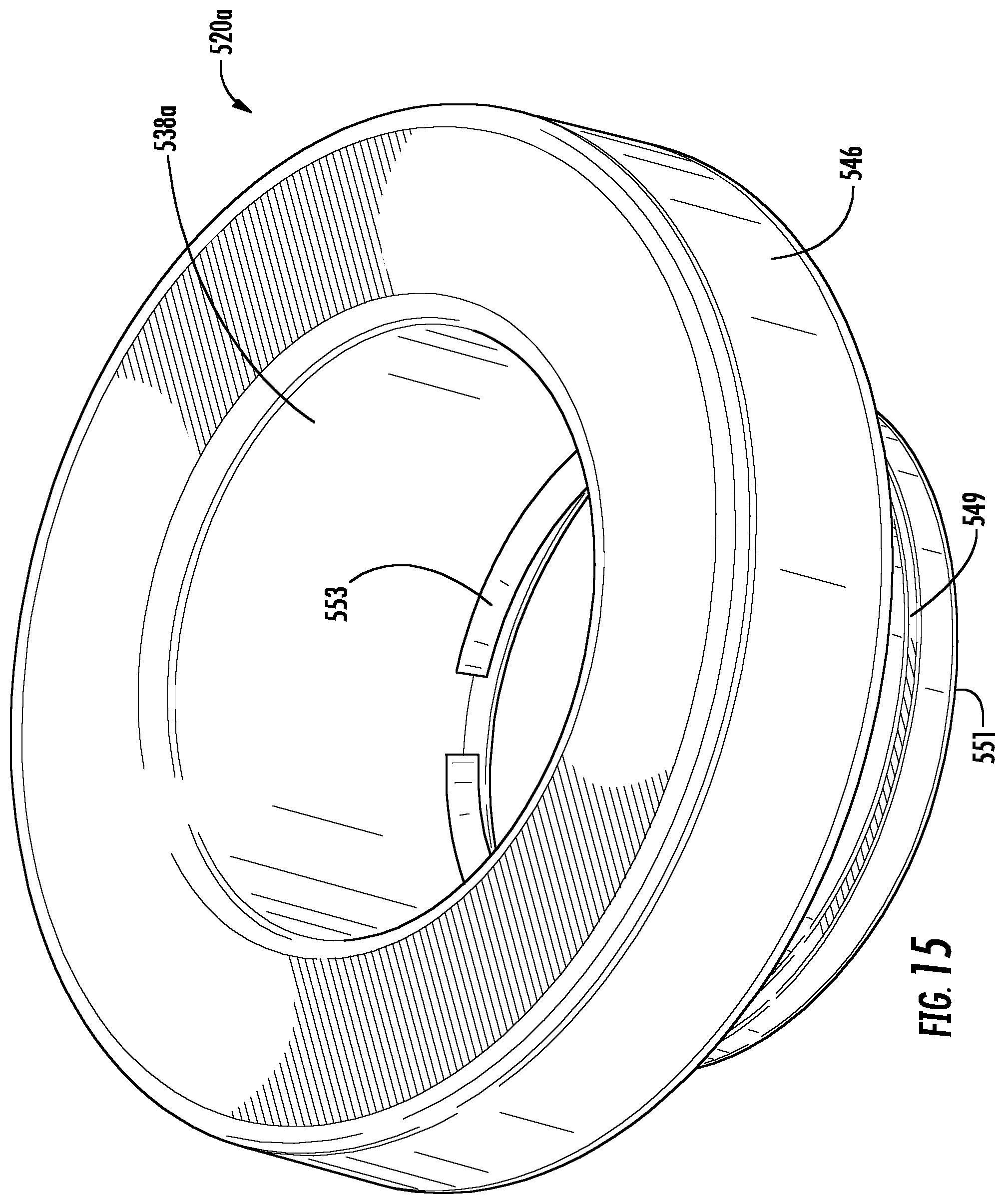
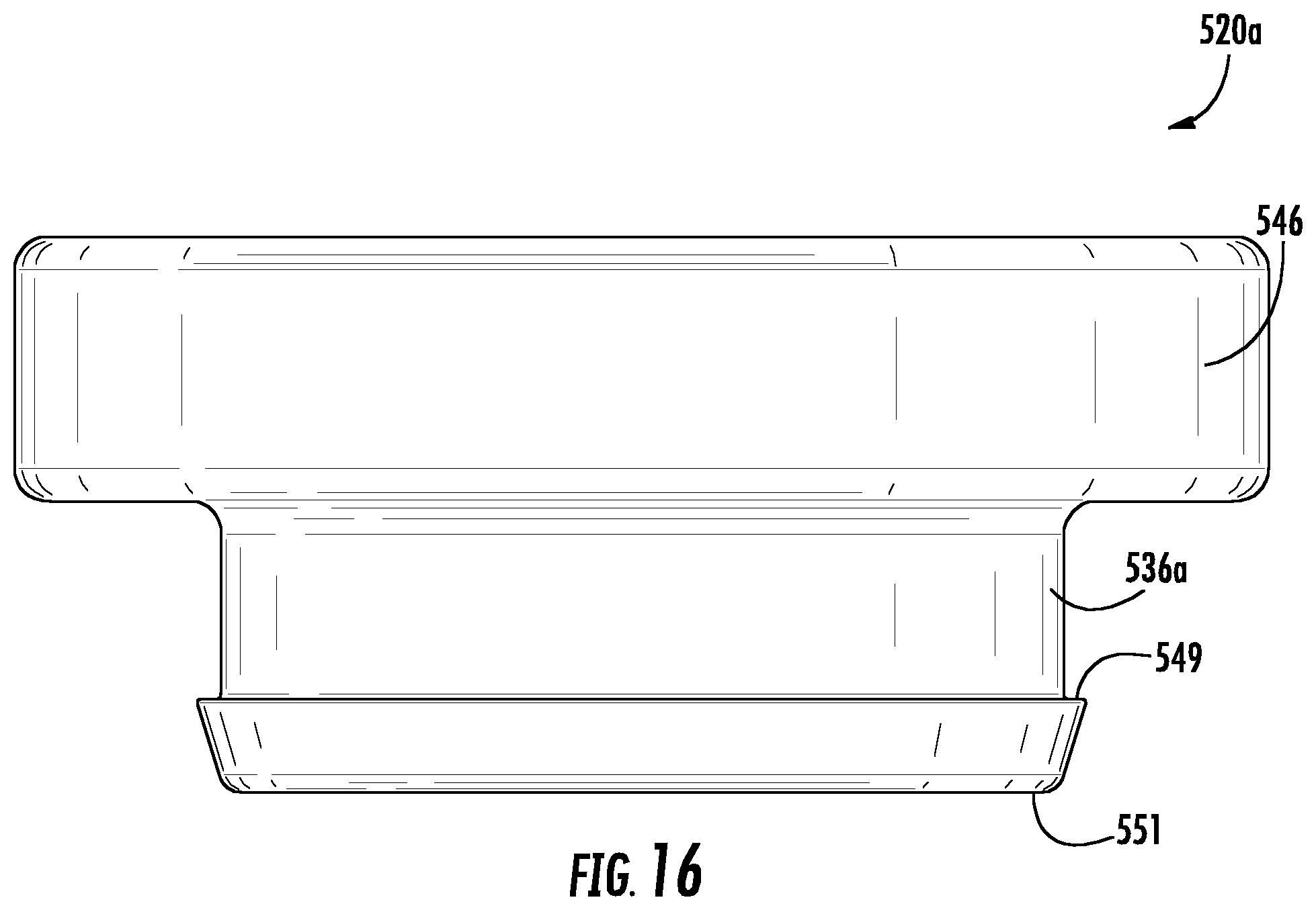
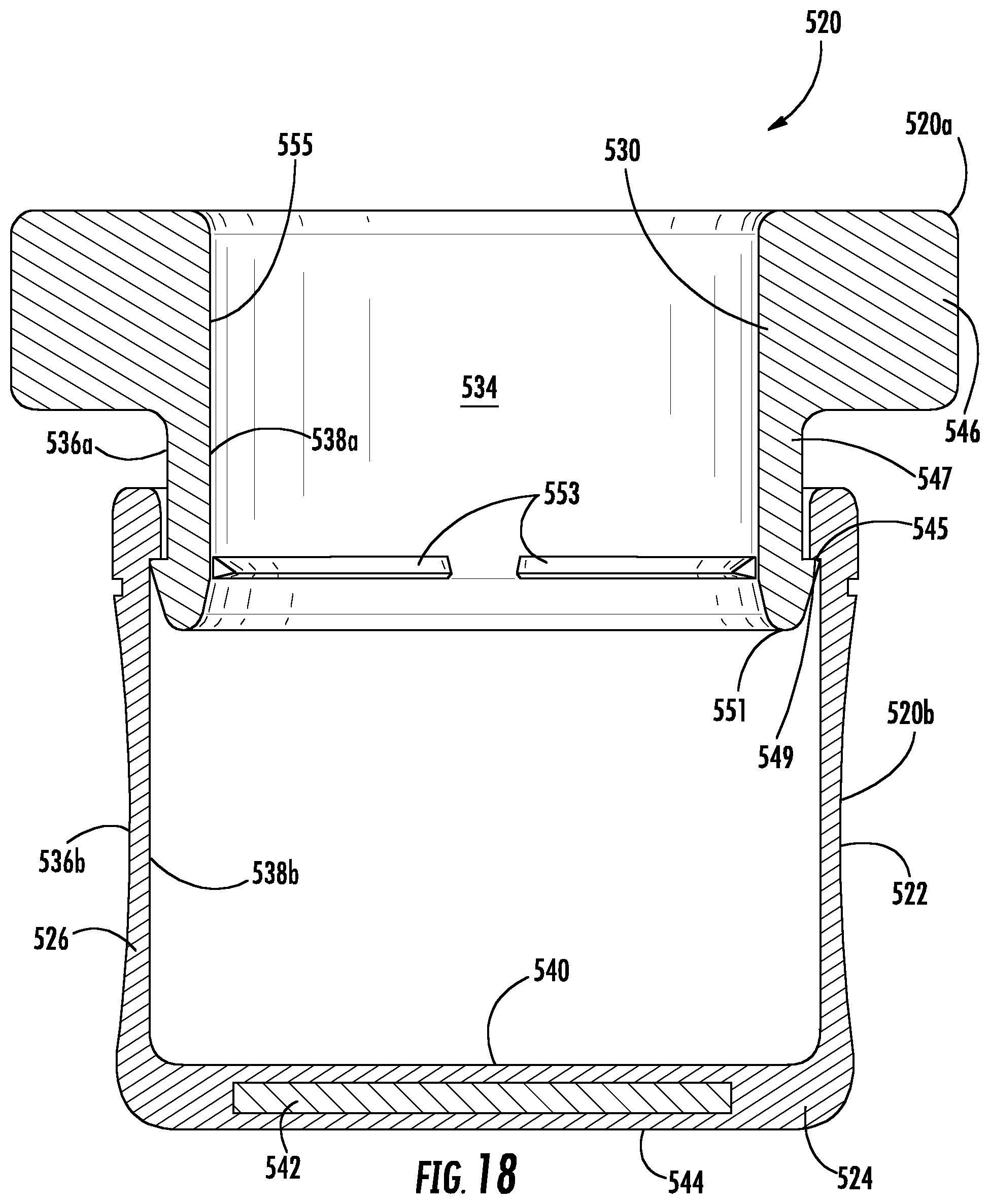
[0070] FIGS. 13-18 show a sixth embodiment of a floatation device 520 with a two-part construction. As illustrated, device 520 includes a top portion 520a and a bottom portion 520b removably attachable to the top portion. Container C1 (e.g., a 12 oz. beverage can) is held within device 520.
[0071] Bottom portion 520b is a cup-shaped body 522, and top portion 520a is a buoyant member 546, as in above embodiments. The top and bottom portions 520a,520b may be formed so as to be removably attachable to each other in numerous ways.
[0072] Fox example, one or both of top portion 520a and bottom portion 520b may be formed flexible enough to allow a sliding friction fit with the other. If desired, bottom portion 520b may have a continuous or discontinuous shoulder 545, and top portion 520a may have a mating continuous or discontinuous shoulder 549. The shoulders 545,549 may be configured to fit together in a bayonet-type snap fit, a dimple-type snap-fit, or in other connections. If desired, shoulders 545,549 could be formed with an axial twist so that they are formed as continuous or discontinuous mating threads, and top portion 520a can therefore be screwed on and off bottom portion 520b.
[0073] Use of a removable top portion 520a with bottom portion 520b provides one or more benefits. For example, shipping and storage of device 520 may be easier with disassembled parts. Also, cleaning of device 520 may be easier if parts 520a and 520b are disassembled. Further, it may be easier to place a container in or remove a container from interior 534 of device 520 if top portion 520a is removed. Also, once a container is in place in interior 534 in separated bottom portion 520b, attaching top portion 520a may help secure the container in place within device 520. One or more of these benefits or others may be provided by the disclosed structure.
[0074] For purposes of weighting and floatation calculations as above, interior volume 534 of device 520 is defined generally by inner surfaces 538a,538b of walls 526 and 547, top surface 540 of base 524, and a point 530 generally along the top 555 of part 520a.
[0075] One or more protrusions 553 may be present on top portion 520a inner surface 538a above lower distal end 551. Such protrusion(s) 553 may provide a radially inward force to assist with holding container C1 in place. Alternatively or additionally, such protrusion(s) may be axially located along the interface between portions 520a,520b, so that presence of container C1 in interior 534 serves to provide a radially outward force to urge the top and bottom portions into engagement (for example, by maintaining contact between shoulders 545,549).
[0076] If desired, bottom portion 520b may be generally rigid (i.e., formed of a hard plastic rather than a foam) for protection and stability during placement on a flat surface. Bottom portion 520b may also include rigid outer layer(s) (exterior and/or interior) and an insulating (and perhaps less dense) inner layer(s). Bottom support surface 544 may be configured so as to be substantially horizontal (as illustrated; perpendicular to a vertical central axis running upward within bottom portion 520b), so as to allow device 520 to be stably placed on a flat surface.
[0077] Upper portion 520 a may be formed of similar material, different material, or multiple materials. For example, wall 547 or portions of it may be relatively harder denser material (for example to provide secure attachment to bottom portion 520b, while buoyant member 546 may be a softer, less dense material such as a foam or the like, as described above. Again, differing inner and outer layers may have different materials. Shoulders 545,549 and/or protrusions 553 may be made of materials the same as, more rigid than, and/or less rigid than the immediately adjacent areas of the respective portions 520a,520b on which they are located.
[0078] FIG. 19 shows an alternate configuration of a device 620 that may be achieved in one of two ways. Note that in FIG. 19, container A is a large tumbler, as opposed to beverage can C1 in FIGS. 13-18. Device 620 is essentially similar to device 520 with one difference. For brevity, description of elements common to devices 520,620 is not provided here, but similar 600-series reference numerals identify similar parts.
[0079] A difference between the embodiments appears in top part 620a, where the inner surface portion 638a is substantially cylindrical and when inner surface portion 638c is substantially non-cylindrical. As illustrated, inner surface portion 638c is of increasing diameter in an upward direction and conforms generally to a portion F of container A. If desired, portion 638c could be of decreasing diameter in an upward direction, for example to conform more closely to a container such as a bottle that tapers from a larger base along or toward a neck and/or opening.
[0080] Inner surface 638c could achieve this shape, for example, if at least some part of top portion 620a is flexible enough to allow the top portion to compress from a cylindrical shape (such as is shown in top portion 520a in FIG. 18) to the shape shown in FIG. 19. Alternatively, inner surface 638c could be molded, formed, etc., in such shape with the goal of conforming to a particular size or general type of container A and its particular or general type of sidewall F. Further, inner surface 638c could be formed with an opposite inward taper (to conform more closely to a bottle, for example), upper portion 620a could be compressible to receive differently shaped (cylindrical or non-cylindrical with opposite tapering) containers.
[0081] If desired, upper portions could be manufactured in one or more configurations for use with containers of different types (cans, bottles, tumblers of different shapes and sizes, etc.), whether custom made for a particular container or generally made for classes of containers. Bottom portion(s) could be sold separately from the top portion(s) in a mix and match fashion to provide a desired combination for a container. Alternatively, one or more bottom portions may be sold with multiple top portions in kit fashion to provide different options for a consumer who might use one bottom portion and different top portions depending on which containers might be used at some point in the future. Also, bottom portions 620b may be differently configured in view of expected container use and well, and mixed and matched as noted above.
[0082] It should be noted that indicia may be located via printing, molding or attachment (stickers) on any part of the floatation device. Flat surfaces or surfaces curving on only one axis such as are found on some of the embodiments may provide ready surfaces for such indicia. By making cup-shaped body 22 not completely cylindrical (and making it more frusto-conical), nestability of multiple devices may be improved. Using buoyant material, distributed so that the larger buoyant portions (buoyant members) are at the top, while ballast-like counter weights are located at the bottom allows for stability while floating, whether full or empty. Making the bottom of the base flat also allows for stability on a solid surface. Thus, a multi-function, weight-stabilized floating beverage container device can be achieved using some or many of the elements of the various embodiments above.
[0083] While preferred embodiments of the invention have been described above, it is to be understood that any and all equivalent realizations of the present invention are included within the scope and spirit thereof. Thus, the embodiments depicted are presented by way of example only and are not intended as limitations upon the present invention. Thus, while particular embodiments of the invention have been described and shown, it will be understood by those of ordinary skill in this art that the present invention is not limited thereto since many modifications can be made. Therefore, it is contemplated that any and all such embodiments are included in the present invention as may fall within the literal or equivalent scope of the appended claims.
* * * * *
D00000
D00001
D00002
D00003
D00004
D00005
D00006
D00007
D00008
D00009
D00010
D00011
D00012
D00013

D00014
D00015
D00016
D00017

D00018
D00019

XML
uspto.report is an independent third-party trademark research tool that is not affiliated, endorsed, or sponsored by the United States Patent and Trademark Office (USPTO) or any other governmental organization. The information provided by uspto.report is based on publicly available data at the time of writing and is intended for informational purposes only.
While we strive to provide accurate and up-to-date information, we do not guarantee the accuracy, completeness, reliability, or suitability of the information displayed on this site. The use of this site is at your own risk. Any reliance you place on such information is therefore strictly at your own risk.
All official trademark data, including owner information, should be verified by visiting the official USPTO website at www.uspto.gov. This site is not intended to replace professional legal advice and should not be used as a substitute for consulting with a legal professional who is knowledgeable about trademark law.