Automatic Analyzer
NAKANO; Hiroki ; et al.
U.S. patent application number 16/646189 was filed with the patent office on 2020-08-27 for automatic analyzer. The applicant listed for this patent is HITACHI HIGH-TECHNOLOGIES CORPORATION. Invention is credited to Hiroki NAKANO, Takenori OKUSA, Yoichiro SUZUKI, Hidetsugu TANOUE.
| Application Number | 20200271679 16/646189 |
| Document ID | / |
| Family ID | 1000004868549 |
| Filed Date | 2020-08-27 |


| United States Patent Application | 20200271679 |
| Kind Code | A1 |
| NAKANO; Hiroki ; et al. | August 27, 2020 |
AUTOMATIC ANALYZER
Abstract
An automatic analyzer which accurately detects a liquid volume of a reagent irrespective of a shape of a reagent container is provided. The invention is directed to an automatic analyzer including: a reagent container that contains a reagent; an emission unit that is provided outside the reagent container and emits light so as to pass inside the reagent container; a light receiving unit that is provided outside the reagent container and receives the light emitted from the emission unit; and a determination unit that, based on the light received by the light receiving unit, detects a liquid level inside the reagent container, and determines whether a liquid volume in the reagent container becomes equal to or less than a predetermined value from the liquid level. A wavelength of the light is determined based on a material of the reagent container and a type of the reagent.
| Inventors: | NAKANO; Hiroki; (Tokyo, JP) ; TANOUE; Hidetsugu; (Tokyo, JP) ; SUZUKI; Yoichiro; (Tokyo, JP) ; OKUSA; Takenori; (Tokyo, JP) | ||||||||||
| Applicant: |
|
||||||||||
|---|---|---|---|---|---|---|---|---|---|---|---|
| Family ID: | 1000004868549 | ||||||||||
| Appl. No.: | 16/646189 | ||||||||||
| Filed: | January 29, 2019 | ||||||||||
| PCT Filed: | January 29, 2019 | ||||||||||
| PCT NO: | PCT/JP2019/002853 | ||||||||||
| 371 Date: | March 11, 2020 |
| Current U.S. Class: | 1/1 |
| Current CPC Class: | G01N 2035/0443 20130101; G01N 35/025 20130101; G01N 35/1016 20130101; G01N 35/04 20130101; G01N 2035/1025 20130101; G01N 35/1002 20130101 |
| International Class: | G01N 35/02 20060101 G01N035/02; G01N 35/10 20060101 G01N035/10; G01N 35/04 20060101 G01N035/04 |
Foreign Application Data
| Date | Code | Application Number |
|---|---|---|
| Mar 16, 2018 | JP | 2018-048755 |
Claims
1.-7. (canceled)
8. An automatic analyzer comprising: a reagent container that contains a reagent; an emission unit that is provided outside the reagent container and emits light so as to pass inside the reagent container; a light receiving unit that is provided outside the reagent container and receives the light emitted from the emission unit; and a determination unit that, based on the light received by the light receiving unit, detects a liquid level inside the reagent container, and determines whether a liquid volume in the reagent container becomes equal to or less than a predetermined value from the liquid level, wherein a wavelength of the light is a wavelength of near-infrared light determined based on a material of the reagent container and a type of the reagent, and an absorbance of light absorbed by the reagent is greater than an absorbance of light absorbed by the container.
9. The automatic analyzer according to claim 8, wherein the wavelength of the light is a wavelength that is blocked by a liquid inside the reagent container and transmits through the reagent container.
10. The automatic analyzer according to claim 8, further comprising: a nozzle through which the reagent is sucked and discharged to the reagent container, wherein the emission unit and the light receiving unit are disposed such that a trajectory of the light avoids the nozzle.
11. The automatic analyzer according to claim 8, wherein the emission unit and the light receiving unit are provided at a height of a predetermined value being a liquid volume where disturbance of an apparatus operation due to shortage of the reagent does not occur.
12. The automatic analyzer according to claim 8, further comprising: a display unit that displays a message for prompting replacement of the reagent container when the liquid volume inside the reagent container becomes equal to or less than the predetermined value.
13. The automatic analyzer according to claim 8, further comprising: a correction unit that corrects a count value of a liquid volume of a sucked reagent to the predetermined value when the determination unit determines that the liquid volume inside the reagent container becomes equal to or less than the predetermined value.
14. The automatic analyzer according to claim 13, further comprising: an initialization unit that initializes the liquid volume, wherein the initialization unit does not perform an initialization operation by the initialization unit when the determination unit determines that the liquid volume inside the reagent container is equal to or less than the predetermined value.
15. An automatic analyzer comprising: a reagent container that contains a reagent; an emission unit that is provided outside the reagent container and emits light so as to pass inside the reagent container; a light receiving unit that is provided outside the reagent container and receives the light emitted from the emission unit; a determination unit that, based on the light received by the light receiving unit, detects a liquid level inside the reagent container, and determines whether a liquid volume in the reagent container becomes equal to or less than a predetermined value from the liquid level; and a correction unit that corrects a count value of a liquid volume of a sucked reagent to the predetermined value when the determination unit determines that the liquid volume inside the reagent container becomes equal to or less than the predetermined value, wherein a wavelength of the light is determined based on a material of the reagent container and a type of the reagent.
16. The automatic analyzer according to claim 15, further comprising: an initialization unit that initializes the liquid volume, wherein the initialization unit does not perform an initialization operation by the initialization unit when the determination unit determines that the liquid volume inside the reagent container is equal to or less than the predetermined value.
Description
TECHNICAL FIELD
[0001] The present invention relates to an automatic analyzer.
BACKGROUND ART
[0002] In an automatic analyzer, a reagent filled in a reagent container is sucked and mixed with a sample (a biological sample such as blood or urine) in a reaction vessel. When there is an abnormality in a suction amount of the reagent, an automatic analysis operation is stopped. Here, there is a method of detecting a liquid level (liquid volume) of the reagent in the reagent container using refraction or reflection of light (see PTL 1).
CITATION LIST
Patent Literature
[0003] PTL 1: JP-A-11-72369
SUMMARY OF INVENTION
Technical Problem
[0004] In PTL 1, deformation of the reagent container is not considered. A resin such as PE or PS may be used as the material of the reagent container, and a wall surface of the reagent container may be thinned for use of a pouch container and cost reduction, so that the wall surface of the reagent container may be distorted when the reagent is filled. When detecting the liquid volume using the reflection or refraction of light, a corresponding shape of the reagent container is limited.
[0005] Accordingly, an object of the invention is to provide an automatic analyzer which detects a liquid volume of a reagent irrespective of a shape of a reagent container.
Solution to Problem
[0006] An automatic analyzer according to an aspect of the invention includes: a reagent container that contains a reagent; an emission unit that is provided outside the reagent container and emits light so as to pass inside the reagent container; a light receiving unit that is provided outside the reagent container and receives the light emitted from the emission unit; and a determination unit that, based on the light received by the light receiving unit, detects a liquid level inside the reagent container, and determines whether a liquid volume in the reagent container becomes equal to or less than a predetermined value from the liquid level, wherein a wavelength of the light is determined based on a material of the reagent container and a type of the reagent.
Advantageous Effect
[0007] According to this invention, the automatic analyzer which detects the liquid volume of the reagent irrespective of the shape of the reagent container can be provided.
BRIEF DESCRIPTION OF DRAWINGS
[0008] FIG. 1 a diagram illustrating an example of a configuration of an automatic analyzer.
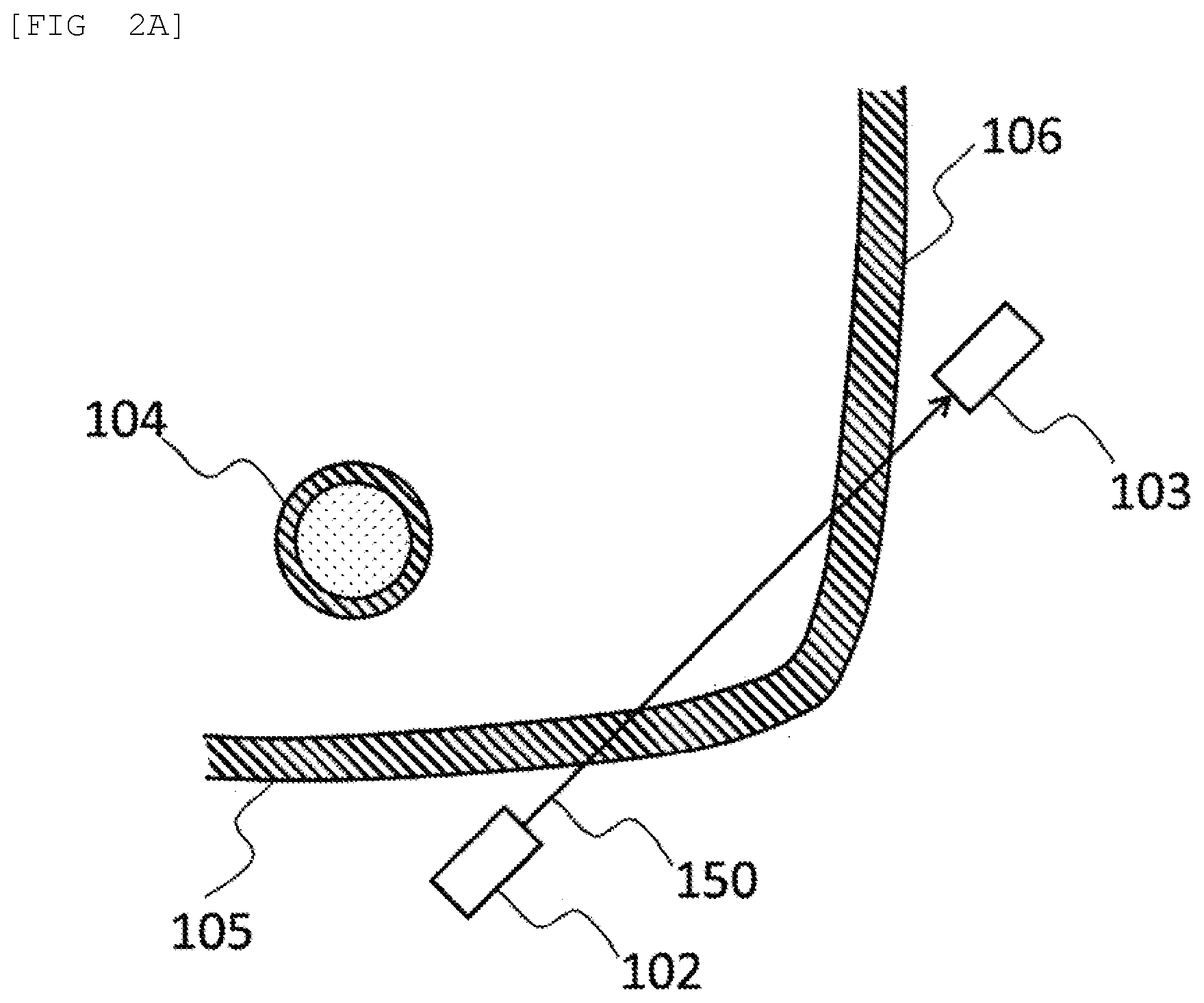
[0009] FIG. 2A is a view of a corner portion of a reagent container in which no reagent exists as viewed from a top.
[0010] FIG. 2B is a view of a corner portion of a reagent container in which a reagent exists as viewed from the top.
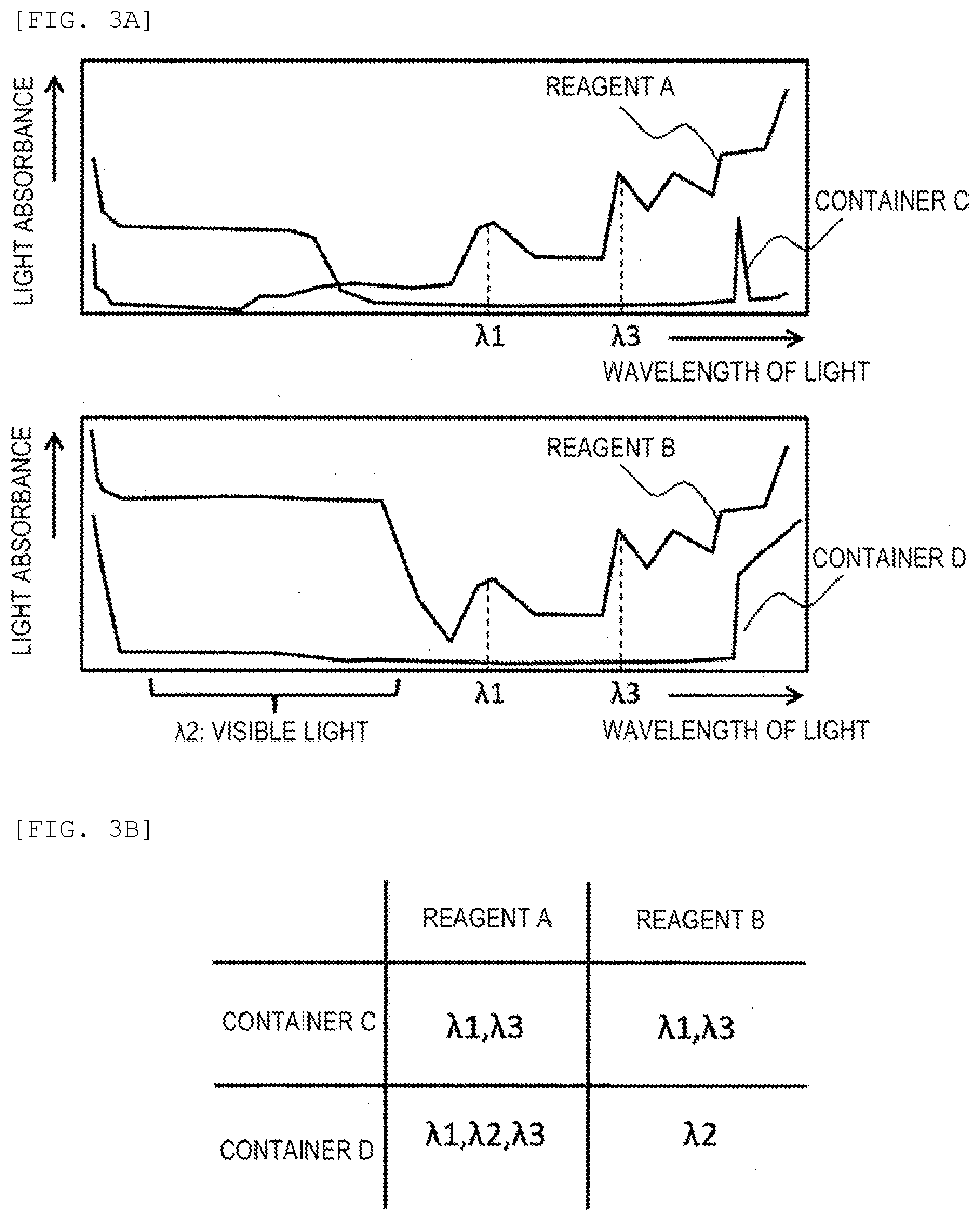
[0011] FIG. 3A is a diagram illustrating light absorption spectra of a reagent and a reagent container.
[0012] FIG. 3B is a diagram a correspondence relationship between wavelengths for the reagent and the reagent container.
[0013] FIG. 4 is a flowchart of a reagent suction cycle.
[0014] FIG. 5 is a flowchart of an initialization cycle of a reagent management amount.
DESCRIPTION OF EMBODIMENTS
[0015] Hereinafter, an embodiment will be described.
First Embodiment
[0016] FIG. 1 is a diagram illustrating an example of a configuration of an automatic analyzer. The automatic analyzer includes an incubator (reaction disk) 887 capable of mounting a plurality of reaction vessels 888 in which a mixture of a sample and a reagent is contained, a reagent container 101 that holds a reagent 107, a nozzle 104 configured to suck the reagent 107 from the reagent container 101, a reagent probe 886 configured to dispense the reagent sucked from the reagent container 101 to the reaction vessel 888, a sample probe 890 configured to dispense the sample sucked from a sample container 891 to the reaction vessel 888, a management unit 110 configured to manage a liquid volume of the reagent 107 in the reagent container 101, and a display unit 115 configured to display information to a user. The reagent probe 886 is connected to a syringe 885 (metering pump) via a dispensing flow path 770, and a valve 772 is provided in a middle of the dispensing flow path 770. The nozzle 104 is connected to the syringe 885 via a dispensing flow path 771, and a valve 773 is provided in a middle of the dispensing flow path 771.
[0017] The reagent probe 886 performs suction of the reagent from the reagent container 101 via the nozzle 104 by the syringe 885 and discharge of the reagent to the reaction vessel 888. The sample probe 890 is rotated vertically and horizontally by a moving mechanism (not shown) to move between the reaction vessel 888 and the sample container 891, and sucks and discharges the sample by a suction and discharge mechanism (not shown).
[0018] The syringe 885 has a pressure sensor, detects a pressure in the dispensing flow paths 770 and 771 when sucking and discharging the sample based on a pressure signal in the flow path, and determines whether the reagent 107 is normally sucked from the nozzle 104. For example, when the pressure sensor determines that the reagent 107 is not normally sucked, such as when the reagent 107 cannot be sucked from the nozzle 104 in a state where the liquid volume of the reagent 107 in the reagent container 101 is almost zero, the management unit 110 stops an apparatus operation so as not to output an abnormal analysis result.
[0019] FIG. 2 is a view of a corner portion of the reagent container as viewed from a top, in which FIG. 2A shows a case where no reagent exists, and FIG. 2B shows a case where a reagent exists.
[0020] An emission unit 102 configured to emit light 150 is provided outside the reagent container 101, and is disposed so that the light 150 transmits inside of the reagent container 101. A light receiving unit 103 configured to receive the light 150 is provided outside the reagent container 101, and is disposed on an optical path of the light 150. The emission unit 102 is formed of a light emitting element such as a light emitting diode, and the light receiving unit 103 is formed of a light receiving element such as a photodiode.
[0021] When the reagent 107 does not exist on the optical path, the light 150 transmits through a wall surface 105 and a wall surface 106 of the reagent container 101 and is received by the light receiving unit 103. On the other hand, when the reagent 107 exists on the optical path, the light 150 is absorbed by the reagent 107 and attenuated, and thus is not received by the light receiving unit 103.
[0022] The emission unit 102 is disposed such that an incident angle is 0<.theta.<90.degree. with respect to the wall surface 105 of the reagent container. The emission unit 102 is disposed such that the nozzle 104 does not exist on the optical path of the light 150 in order to prevent the light 150 from being blocked by the nozzle 104. The light receiving unit 103 is disposed such that an emission angle is 0<.theta.<90.degree. with respect to the wall surface 106 of the reagent container. The emission unit 102 and the light receiving unit 103 are provided at a height of a predetermined value corresponding to a liquid volume at which disturbance of an apparatus operation due to shortage of the reagent does not occur.
[0023] The emission unit 102 and the light receiving unit 103 are provided to face each other with the reagent container 101 being interposed therebetween at a height H at which the reagent 107 has a predetermined amount Va. For example, when the rectangular parallelepiped reagent container 101 has a bottom area S, the height H at which the liquid volume of the reagent 107 in the reagent container 101 becomes the predetermined amount Va is determined by H=Va/S=(Vd+Vt)/S. That is, the height H is a value obtained by adding a reagent liquid volume Vt required for an operation of analyzing the number of cells that can be stored in the incubator 887 to a minimum amount Vd at which the reagent cannot be sucked from the nozzle 104, and then dividing by the bottom area S. For a reagent container with an undefined outer shape such as a pouch, the liquid height cannot be specified by calculation based on the above container cross-sectional area. In that case, the predetermined value Va is defined based on a height of a suction port of the nozzle and the liquid height.
[0024] FIG. 3 is a diagram showing a relationship between the reagent and the reagent container, in which FIG. 3A is a diagram illustrating light absorption spectra of the reagent and the reagent container, and FIG. 3B is a diagram illustrating a correspondence relationship between wavelengths for the reagent and the reagent container.
[0025] A wavelength of the light 150 is selected based on a material of the reagent container 101 and a type of the reagent 107. For example, in a case of a combination of the reagent 107 being a substantially colorless reagent A containing moisture that is transparent and transmits visible light and the reagent container 101 being a translucent or opaque colored rectangular parallelepiped container C having a color such as white formed of a plastic resin such as polyethylene or polystyrene, near-infrared light having a wavelength of .lamda.1 (about 1450 nm) or .lamda.3 (about 1940 nm) which is absorbed by the moisture contained in the reagent A and is well transmitted through the plastic resin is used. In addition, in a case of a combination of the reagent 107 being a colored reagent B such as white and the reagent container 101 being a transparent (substantially colorless) cylindrical container D made of glass such as borosilicate glass or soda-lime glass, visible light having a wavelength of .lamda.2 (400 nm to 800 nm) which is dispersed or absorbed in the reagent B and is well transmitted through the container D is used. Similarly, in a case of a combination of the reagent A and the container D (colorless reagent and colorless container), one of .lamda.1, .lamda.2, .lamda.3 is used, and in a case of a combination of the reagent B and the container C (colored reagent and colored container), .lamda.1 or .lamda.3 is used. In addition, the wavelength may be selected according to a variation of the combination.
[0026] In this way, by determining the wavelength of the light 150 based on the material of the reagent container and the type of the reagent, the liquid level of the reagent can be detected regardless of a shape of the container, for example, even for a reagent container having an undefined outer shape such as a pouch and an undefined angle between the wall surface and an optical axis. It is possible to eliminate restrictions on the arrangement such that the incident angle or the emission angle is 0<.theta.<90.degree..
[0027] Next, the management unit 110 will be described. The management unit 110 includes a calculation unit 111 configured to calculate a remaining liquid amount based on a used liquid amount, a determination unit 112 configured to determine, based on whether the light 150 is received by the light receiving unit 103, whether a liquid level of the reagent 107 is equal to or less than the height H, an initialization unit 113 configured to initialize the liquid volume, and a warning unit 114 configured to display on the display unit 115 a message notifying that the liquid volume of the reagent 107 in the reagent container 101 is low, and prompt an operator to replace the reagent container 101 when the determination unit 112 determines that the liquid level of the reagent 107 is equal to or less than the height H.
[0028] Here, the calculated liquid volume of the reagent 107 in the reagent container 101 managed by the management unit 110 is defined as a management liquid volume V(x) (x is the number of times of suction), the liquid volume sucked from the reagent container 101 is defined as a suction liquid volume Vu, and the liquid volume of the reagent 107 contained in a new reagent container 101 is defined as an initial liquid volume V(0).
[0029] The calculation unit 111 calculates a current management liquid volume V(x) using the suction liquid volume Vu sucked from the reagent container 101 by driving the syringe 885. The management liquid volume V(x) is a value (V(x)=V(x-1)-Vu) obtained by subtracting the suction liquid volume Vu from a management liquid volume V(x-1) before sucking the reagent.
[0030] The initialization unit 113 sets the management liquid volume V(x) to an initial value V(0). An initialization operation is performed according to a command from an initialization trigger 116 (such as a switch). When the reagent container 101 is replaced with a new one, by executing the initialization operation by the initialization trigger 116, the management unit 110 recognizes that the current reagent container 101 contains an initial amount V(0).
[0031] When the determination unit 112 determines that the liquid level of the reagent 107 is equal to or less than H (the liquid volume is the predetermined amount Va), the management unit 110 corrects the management liquid volume V(x) to a value of the predetermined amount Va, and sets a correction flag F to 1. The correction flag is a flag for determining whether the correction is executed, and is 0 when a correction operation is not executed, and is 1 when the correction operation is executed. Here, when F=1 (the liquid volume correction operation has already been executed), even if the determination unit 112 determines that the liquid volume of the reagent 107 is equal to or less than the predetermined amount Va, the liquid volume correction operation is not executed.
[0032] FIG. 4 is a flowchart of a reagent suction operation performed by the management unit 110.
[0033] First, the management unit 110 controls the nozzle 104 to suck the reagent 107 from the reagent container 101 (S401). At this time, the calculation unit 111 sets a value obtained by subtracting the suction liquid volume Vu from the management liquid volume V(x-1) before suction as the current management liquid volume V(x).
[0034] Next, the management unit 110 determines whether F=0 (S402). When F=1, the management unit 110 ends a reagent suction cycle without performing the liquid volume correction operation. When F=0, the determination unit 112 determines whether the liquid volume of the reagent 107 is equal to or less than Va (whether the light receiving unit 103 detects light) (S403). When the determination unit 112 determines that the liquid volume of the reagent 107 is greater than Va, the management unit 110 ends the reagent suction cycle, and when the determination unit 112 determines that the liquid volume of the reagent liquid 107 is equal to or less than Va, the management unit 110 sets the management liquid volume V(x) to the predetermined value Va (S404). The management unit 110 sets F to 1 (S405), and controls the warning unit 114 to display a message for prompting reagent replacement on the display unit 115 (S406).
[0035] When the correction according to this flow is not performed, for example, when an actual liquid volume is larger than the management liquid volume, if the management liquid volume becomes 0, the reagent container 101 is replaced even though the actual liquid volume remains, and waste increases. In addition, when the actual liquid volume is smaller than the management liquid volume, the management liquid volume exists even if the actual liquid volume becomes 0, and therefore, suction (empty suction) is performed in a state where no reagent exists. However, according to this flow, such a problem can be avoided because when the actual liquid volume and the management liquid volume are different, the management liquid volume and the actual liquid volume are corrected to substantially the same value with the fact that the liquid level of the reagent 107 becomes equal to or less than H as a trigger.
[0036] FIG. 5 is a flowchart of an initialization operation of the management liquid volume V(x) by the management unit 110.
[0037] Upon receiving a command from the initialization trigger 116 (S501), the initialization unit 113 determines whether the liquid volume of the reagent 107 is equal to or less than Va (S502). When it is determined that the liquid volume of the reagent 107 is equal to or less than Va, the initialization unit 113 does not execute the initialization operation. When it is determined that the liquid volume of the reagent 107 is greater than Va, the initialization unit 113 sets the management liquid volume V (x) to the initial value V (0) (S503), and sets F to 0 (S504).
[0038] This flow is significant in that the management unit 110 can perform the liquid volume correction. When the reagent is above the light 150, the liquid volume correction can be performed by the flow of FIG. 4. On the other hand, when the liquid volume correction is not performed despite the reagent being below the light 150, since there is no chance to perform the liquid volume correction, the empty suction of the reagent may be generated. Accordingly, an initialization of the management liquid volume can avoid the empty suction of the reagent. The initialization trigger 116 is activated by a user pressing a switch. However, a sensor that monitors an installation of the reagent container 101 may be provided, and the initialization trigger 116 may be activated based on a signal from the sensor.
[0039] According to the above embodiment, it is possible to accurately detect the reagent liquid volume regardless of the shape of the reagent container. A consistency of the initial liquid volume generated due to various factors (in a case where the user spills a new reagent container, initializes the management liquid volume for the reagent container in use, or the like) can be corrected. By correcting a reagent amount, it is possible to avoid an abnormality in the suction amount of the reagent and to prevent wasteful consumption of the sample. Further, a remaining amount of the reagent after use can be minimized, and a running cost of the apparatus can be reduced.
REFERENCE SIGN LIST
[0040] 101: reagent container [0041] 102: emission unit [0042] 103: light receiving unit [0043] 104: nozzle [0044] 105: wall surface of reagent container on side of emission unit [0045] 106: wall surface of reagent container on side of light [0046] receiving unit [0047] 107: reagent inside reagent container [0048] 110: management unit [0049] 111: calculation unit [0050] 112: determination unit [0051] 113: initialization unit [0052] 114: warning unit [0053] 115: display unit [0054] 116: initialization trigger [0055] 770: flow path (on side of reagent probe) [0056] 771: flow path (on side of nozzle) [0057] 772: valve (on side of reagent probe) [0058] 773: valve (on side of nozzle) [0059] 885: syringe [0060] 886: reagent probe [0061] 887: incubator [0062] 888: reaction vessel [0063] 890: sample probe [0064] 891: sample container
* * * * *
D00000
D00001
D00002
D00003
D00004
D00005
D00006
XML
uspto.report is an independent third-party trademark research tool that is not affiliated, endorsed, or sponsored by the United States Patent and Trademark Office (USPTO) or any other governmental organization. The information provided by uspto.report is based on publicly available data at the time of writing and is intended for informational purposes only.
While we strive to provide accurate and up-to-date information, we do not guarantee the accuracy, completeness, reliability, or suitability of the information displayed on this site. The use of this site is at your own risk. Any reliance you place on such information is therefore strictly at your own risk.
All official trademark data, including owner information, should be verified by visiting the official USPTO website at www.uspto.gov. This site is not intended to replace professional legal advice and should not be used as a substitute for consulting with a legal professional who is knowledgeable about trademark law.