Method And Apparatus For Performing Multi-energy (including Dual Energy) Computed Tomography (ct) Imaging
Worstell; William A. ; et al.
U.S. patent application number 16/588024 was filed with the patent office on 2020-08-27 for method and apparatus for performing multi-energy (including dual energy) computed tomography (ct) imaging. The applicant listed for this patent is Photo Diagnostic Systems,Inc. Invention is credited to Bernard M. Gordon, Olof Johnson, Matthew Len Keeler, William A. Worstell.
| Application Number | 20200271597 16/588024 |
| Document ID | / |
| Family ID | 1000004816196 |
| Filed Date | 2020-08-27 |


| United States Patent Application | 20200271597 |
| Kind Code | A1 |
| Worstell; William A. ; et al. | August 27, 2020 |
METHOD AND APPARATUS FOR PERFORMING MULTI-ENERGY (INCLUDING DUAL ENERGY) COMPUTED TOMOGRAPHY (CT) IMAGING
Abstract
An improved dual energy CT imaging system for providing improved imaging and improved material identification.
| Inventors: | Worstell; William A.; (Wayland, MA) ; Keeler; Matthew Len; (Bolton, MA) ; Johnson; Olof; (Ashburnham, MA) ; Gordon; Bernard M.; (Manchester, MA) | ||||||||||
| Applicant: |
|
||||||||||
|---|---|---|---|---|---|---|---|---|---|---|---|
| Family ID: | 1000004816196 | ||||||||||
| Appl. No.: | 16/588024 | ||||||||||
| Filed: | September 30, 2019 |
Related U.S. Patent Documents
| Application Number | Filing Date | Patent Number | ||
|---|---|---|---|---|
| 15217742 | Jul 22, 2016 | 10429323 | ||
| 16588024 | ||||
| 62196422 | Jul 24, 2015 | |||
| Current U.S. Class: | 1/1 |
| Current CPC Class: | A61B 6/4241 20130101; G01V 5/0041 20130101; G01N 23/046 20130101; G01N 2223/423 20130101; A61B 6/4042 20130101; A61B 6/4035 20130101; G01N 2223/401 20130101; A61B 6/405 20130101; G01N 23/087 20130101; G21K 1/10 20130101; A61B 6/032 20130101; A61B 6/52 20130101; A61B 6/5205 20130101; A61B 6/482 20130101; G01V 5/005 20130101; A61B 6/4233 20130101; G01N 2223/313 20130101 |
| International Class: | G01N 23/046 20060101 G01N023/046; G01N 23/087 20060101 G01N023/087; A61B 6/03 20060101 A61B006/03; A61B 6/00 20060101 A61B006/00; G21K 1/10 20060101 G21K001/10; G01V 5/00 20060101 G01V005/00 |
Claims
1.-21. (canceled)
22. A system for providing a first energy measurement associated with a first X-ray energy range produced by a polychromatic X-ray tube, and a second energy measurement associated with a second X-ray energy range produced by the same polychromatic X-ray tube, wherein the second X-ray energy range is different from the first X-ray energy range, the system comprising: a filtered detector for detecting X-rays produced by the polychromatic X-ray tube across the first X-ray energy range and providing an output, wherein the output of the filtered detector comprises the first energy measurement; an unfiltered detector for detecting X-rays produced by the polychromatic X-ray tube across the full X-ray energy range of the polychromatic X-ray tube and providing an output; and a processor for determining the second energy measurement, wherein the second energy measurement is the difference between the output of the unfiltered detector and the output of the filtered detector.
23. A system according to claim 22 wherein the first X-ray energy range comprises higher energy photons and the second X-ray energy range comprises lower energy photons.
24. A system according to claim 23 wherein the filtered detector comprises a detector and a filter interposed between the polychromatic X-ray tube and the detector, and further wherein the filter is configured to block lower energy photons.
25. A system according to claim 22 further comprising a polychromatic X-ray tube.
26. A system according to claim 22 wherein an object is disposed between (i) the polychromatic X-ray tube, and (ii) the filtered detector and the unfiltered detector.
27. A method for providing a first energy measurement associated with a first X-ray energy range produced by a polychromatic X-ray tube, and a second energy measurement associated with a second X-ray energy range produced by the same polychromatic X-ray tube, wherein the second X-ray energy range is different from the first X-ray energy range, the method comprising: providing a system for providing a first energy measurement associated with a first X-ray energy range produced by a polychromatic X-ray tube, and a second energy measurement associated with a second X-ray energy range produced by the same polychromatic X-ray tube, wherein the second X-ray energy range is different from the first X-ray energy range: a filtered detector for detecting X-rays produced by the polychromatic X-ray tube across the first X-ray energy range and providing an output, wherein the output of the filtered detector comprises the first energy measurement; an unfiltered detector for detecting X-rays produced by the polychromatic X-ray tube across the full X-ray energy range of the polychromatic X-ray tube and providing an output; and a processor for determining the second energy measurement, wherein the second energy measurement is the difference between the output of the unfiltered detector and the output of the filtered detector; using the polychromatic X-ray tube to cause the full X-ray energy range of the polychromatic X-ray tube to be received by the filtered detector and the unfiltered detector; and using the filtered detector to determine the first energy measurement, and using the processor to determine the second energy measurement.
28. A method according to claim 27 wherein the first X-ray energy range comprises higher energy photons and the second X-ray energy range comprises lower energy photons.
29. A method according to claim 28 wherein the filtered detector comprises a detector and a filter interposed between the polychromatic X-ray tube and the detector, and further wherein the filter is configured to block lower energy photons.
30. A method according to claim 27 wherein the system further comprises a polychromatic X-ray tube.
31. A method according to claim 27 wherein an object is disposed between (i) the polychromatic X-ray tube, and (ii) the filtered detector and the unfiltered detector.
Description
REFERENCE TO PENDING PRIOR PATENT APPLICATION
[0001] This patent application claims benefit of pending prior U.S. Provisional Patent Application Ser. No. 62/196,422, filed Jul. 24, 2015 by Photo Diagnostic Systems, Inc. and William A. Worstell et al. for METHOD AND APPARATUS FOR PERFORMING DUAL ENERGY COMPUTED TOMOGRAPHY (CT) IMAGING (Attorney's Docket No. PDSI-1 PROV), which patent application is hereby incorporated herein by reference.
FIELD OF THE INVENTION
[0002] This invention relates to imaging systems in general, and more particularly to computed tomography (CT) imaging systems.
BACKGROUND OF THE INVENTION
[0003] In many situations it can be desirable to image the interior of an object. By way of example but not limitation, in the medical field, it can be desirable to image the interior of a patient's body so as to allow viewing of internal structures without physically penetrating the skin. By way of further example but not limitation, in the security field, it can be desirable to image the interior of a container (e.g., a suitcase, a package, etc.) so as to allow viewing of internal structures without physically opening the container.
Computed Tomography (CT)
[0004] Computed Tomography (CT) has emerged as a key imaging modality in the medical and security fields, among others. CT imaging systems generally operate by directing X-rays into an object (e.g., a body or a container) from a variety of positions, detecting the X-rays passing through the object, and then processing the detected X-rays so as to build a three-dimensional (3D) data set, and a 3D computer model, of the interior of the object (e.g., the patient's anatomy or the contents of the container). The 3D data set and 3D computer model can then be visualized so as to provide images (e.g., slice images, 3D computer images, etc.) of the interior of the object (e.g., the patient's anatomy or the contents of the container).
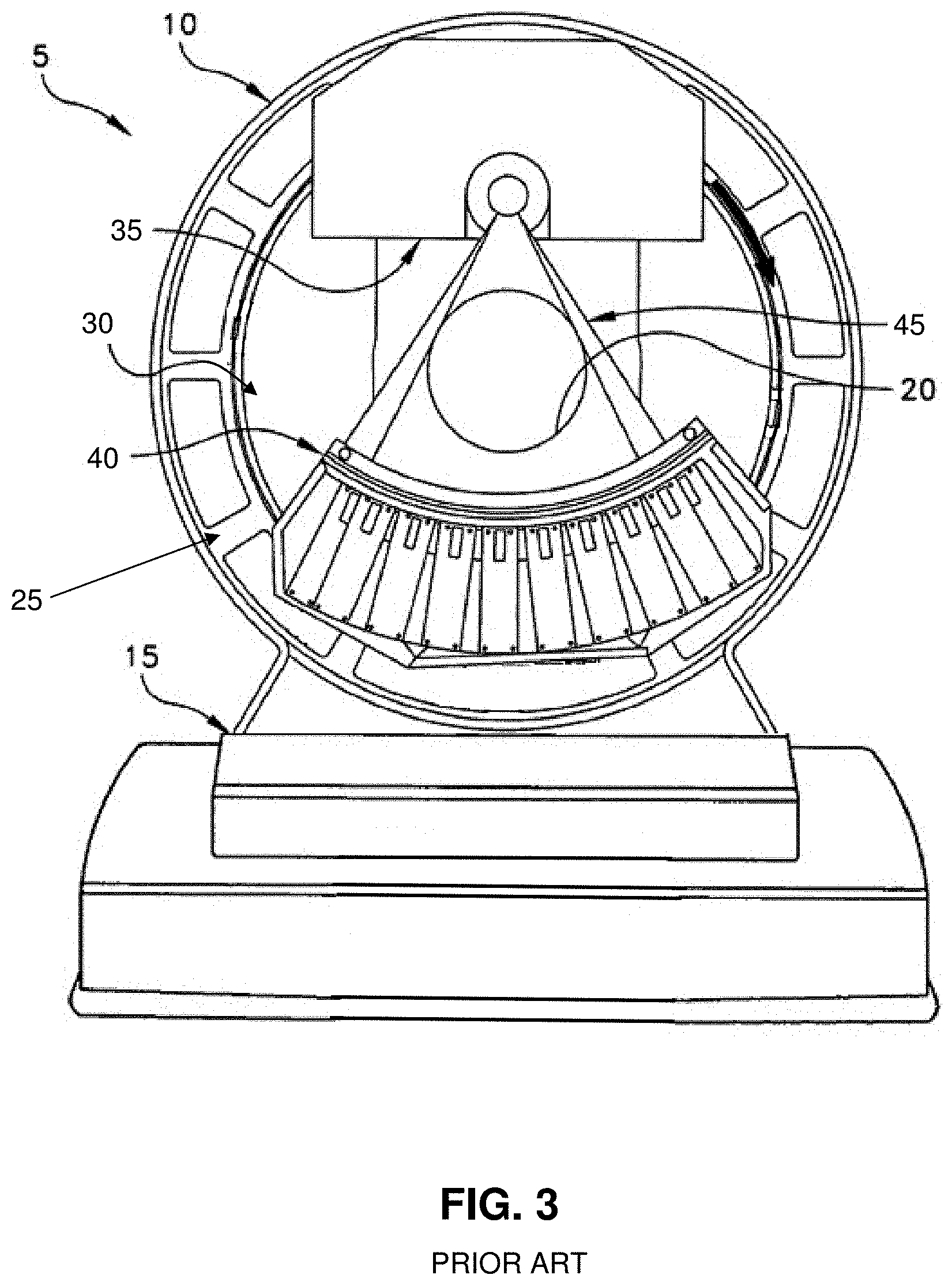
[0005] By way of example but not limitation, and looking now at FIGS. 1 and 2, there is shown an exemplary prior art CT imaging system 5. CT imaging system 5 generally comprises a torus 10 which is supported by a base 15. A center opening 20 is formed in torus 10. Center opening 20 receives the object (e.g., the body or the container) which is to be scanned by CT imaging system 5.
[0006] Looking next at FIG. 3, torus 10 generally comprises a fixed gantry 25, a rotating disc 30, an X-ray tube assembly 35 and an X-ray detector assembly 40. More particularly, fixed gantry 25 is disposed concentrically about center opening 20. Rotating disc 30 is rotatably mounted to fixed gantry 25. X-ray tube assembly 35 and X-ray detector assembly 40 are mounted to rotating disc 30 in diametrically-opposing relation, such that an X-ray beam 45 (generated by X-ray tube assembly 35 and detected by X-ray detector assembly 40) is passed through the object (e.g., the body or the container) disposed in center opening 20. Inasmuch as X-ray tube assembly 35 and X-ray detector assembly 40 are mounted on rotating disc 30 so that they are rotated concentrically about center opening 20, X-ray beam 45 will be passed through the object (e.g., the body or the container) along a full range of radial positions, so as to enable CT imaging system 5 to create a "slice" image of the object penetrated by the X-ray beam. Furthermore, by moving the object (e.g., the body or the container) and/or CT imaging system 5 relative to one another during scanning, a series of slice images can be acquired, and thereafter appropriately processed, so as to create a 3D data set of the scanned object and a 3D computer model of the scanned object.
[0007] In practice, it is now common to effect helical scanning of the object so as to generate a 3D data set of the scanned object, which can then be processed to build a 3D computer model of the scanned object. The 3D data set and/or 3D computer model can then be visualized so as to provide images (e.g., slice images, 3D computer images, etc.) of the interior of the object (e.g., the patient's anatomy or the contents of the container).
Beam Hardening
[0008] In practice, X-ray tube assembly 35 is typically a polychromatic X-ray source, i.e., X-ray tube assembly 35 typically comprises an X-ray tube of the sort which emits X-rays with a range of different energies. However, as the X-ray beam from a polychromatic X-ray source passes through the object which is being scanned, low energy X-ray photons are generally attenuated more easily than high energy X-ray photons. Thus, the X-ray beam from a polychromatic X-ray source preferentially loses the lower-energy parts of its spectrum as it passes through the object. This is a particular problem with high atomic number materials such as bone and metals which can heavily attenuate the lower-energy parts of the X-ray beam, and can (among other things) produce image artifacts between two high attenuation materials (e.g., between two materials which have high atomic numbers). This phenomenon is sometimes referred to as "beam hardening". Various algorithms have been developed in an effort to correct for beam hardening, but such algorithms generally suffer from the fact that they require certain assumptions to be made (e.g., that the polychromatic X-ray source has a fixed spectrum which does not change as the X-ray tube heats up, that the X-ray absorption spectrum has an idealized shape, etc.).
Dual Energy CT
[0009] X-ray attenuation is generally caused by (i) the scattering of radiation by the object which is being scanned, and/or (ii) the absorption of radiation by the object which is being scanned. The mechanisms primarily responsible for these two effects are Compton scatter and photoabsorption. Compton scatter and photoabsorption vary according to (a) the energy of the photons in the X-rays, and (b) the composition of the object which is being scanned. For this reason, it has been recognized that measurements taken at two different X-ray energies (i.e., "dual energy") can be used to distinguish between different materials in the object which is being scanned. These two different measured X-ray energies are not necessarily restricted to monochromatic measurements, and in practice the two measurements are taken over broad ranges of low and high energies (i.e., a low-energy polychromatic measurement is used as one of the X-ray energies of the dual energy scan, and a high-energy polychromatic measurement is used as the other of the X-ray energies of the dual energy scan).
[0010] Several different approaches can be used to generate measurements of two different X-ray energy ranges.
[0011] First, two different X-ray spectra can be applied to the object which is being scanned, and an unfiltered detector can be used to detect the differences in attenuation by the object which is being scanned. Accordingly, with some dual energy CT imaging systems, the system is provided with a single X-ray tube with rapid switching between two different voltages, and an unfiltered detector is used to detect the differences in attenuation by the object which is being scanned with two different X-ray voltages. However, this approach suffers from relatively high cost, since it requires that the single X-ray tube be driven by two different voltages, which generally requires the provision of either two high-voltage power supplies or a single high-speed switching power supply. With other dual energy CT imaging systems, the system is provided with two X-ray tubes driven at different voltages (whereby to apply two different X-ray spectra to the object which is being scanned), and an unfiltered detector is used to detect the differences in attenuation by the object which is being scanned by the two different X-ray tubes/two different X-ray tube voltages. However, this approach also suffers from relatively high cost, since it requires the provision of two X-ray tubes.
[0012] Second, it has also been recognized that a single X-ray spectra can be applied to the object which is being scanned, and then a dual-filter detector (i.e., a detector having two different X-ray spectrum filters) can be used to obtain measurements over two different X-ray energy ranges (e.g., a "high" X-ray energy band and a "low" X-ray energy band), whereby to detect the differences in attenuation by the object which is being scanned. Accordingly, with some dual energy CT imaging systems, the system is provided with a single X-ray tube driven by a single voltage, and a dual-filter detector is used to obtain measurements over two different X-ray energy ranges, i.e., one filter is configured to maximize the detection of higher energy photons and one filter is configured to maximize the detection of lower energy photons. However, this approach suffers from relatively inefficient use of the available photons, because each filter must be something of a compromise in determining what fraction of the photons of the "undesired" spectrum must be allowed to pass in order to get some portion of the photons of the "desired" spectrum. Stated another way, the two filters used in the dual-filter detector cannot cut off at an infinite rate, therefore, the design of each filter must be something of a compromise.
[0013] Again, where the X-ray source is a polychromatic X-ray source (i.e., the X-ray tube assembly emits X-rays with a range of different energies), issues arise due to beam hardening (i.e., the preferential attenuation of low energy X-ray photons by the object being scanned). This can create issues in material identification. Again, various algorithms have been developed in an effort to correct for beam hardening, but such algorithms generally suffer from the fact that they require certain assumptions to be made (e.g., that the polychromatic X-ray source has a fixed spectrum which does not change as the X-ray tube heats up, that the X-ray absorption spectrum has an idealized shape, etc.).
[0014] Thus there is a need for an improved multi-energy (including dual energy) CT imaging system providing improved imaging (e.g., images free of beam hardening artifacts or approximations) and improved material identification.
SUMMARY OF THE INVENTION
[0015] These and other objects of the present invention are addressed by the provision and use of an improved multi-energy (including dual energy) CT imaging system providing improved imaging (e.g., images free of beam hardening artifacts or approximations) and improved material identification.
[0016] In one preferred form of the invention, there is provided a novel approach for performing dual energy CT imaging.
[0017] First, the object is scanned using a CT imaging system comprising (i) an X-ray tube assembly comprising a single X-ray tube driven at a single voltage and producing a polychromatic X-ray beam, and (ii) an X-ray detector assembly wherein each detector is capable of measuring two different X-ray energy ranges, i.e., a "high energy measurement" and a "low energy measurement". This may be done using conventional "dual-filter" detectors or using a novel "single-filter" detector as described herein. In either case, such scanning produces two polyenergetic signals, g.sub.HIGH ("high energy") and g.sub.LOW ("low energy"), for each rotational position of the X-ray tube assembly/X-ray detector assembly about the object which is being scanned, i.e., for each "line of response". In general, additional filters (or their functional equivalent) may be used to obtain additional polyenergetic signals which can be used to further supplement the available spectral information, e.g., appropriate filtering may be provided to generate three or more polyenergetic signals for enabling multi-energy CT.
[0018] Next, for each line of response, the ratio g.sub.HIGH/g.sub.LOW (or "R") is computed.
[0019] R and g (i.e., g.sub.HIGH or g.sub.LOW) are then used as the indices for an appropriate lookup table to obtain multiplicative factors ("A" or "B", respectively) to transform the polyenergetic data g (i.e., g.sub.HIGH or g.sub.LOW, respectively) into the predicted signal for a purely monochromatic system of any monoenergy. The monoenergetic sinogram (G.sub.ENERGY) comprises the collection of monoenergetic signals for any single energy (subscript ".sub.ENERGY") at every line of response including the lines of response associated with both highly filtered (g.sub.HIGH) and lesser filtered or unfiltered (g.sub.LOW) detectors. Note that the function R need not be the specific ratio g.sub.HIGH/g.sub.LOW, or any other ratio for that matter, but may be any function which is sensitive to the differential response of the two (or more) different kinds of detector channels g.sub.HIGH and g.sub.LOW.
[0020] A lookup table (comprising the appropriate multiplicative factors "A.sub.ENERGY.sup." and "B.sub.ENERGY.sup.") can be generated to produce a corresponding monochromatic sinogram G.sub.ENERGY, and from there, a corresponding image for any single monoenergy (subscript ".sub.ENERGY"). By way of example but not limitation, a lookup table (comprising the appropriate multiplicative factors "A.sub.160" and "B.sub.160") can be generated to produce a corresponding monochromatic sinogram G.sub.160 (i.e., a corresponding monochromatic sinogram at monoenergy 160 kev), and from there, a corresponding image I.sub.160 for that monoenergy (i.e., a corresponding image for that monoenergy 160 kev). By way of further example but not limitation, a lookup table (comprising the appropriate multiplicative factors "A.sub.40" and "B.sub.40") can be generated to produce a corresponding monochromatic sinogram G.sub.40 (i.e., a corresponding monochromatic sinogram at monoenergy 40 kev), and from there, a corresponding image I.sub.40 for that monoenergy (i.e., a corresponding image for that monoenergy 40 kev).
[0021] Significantly, these "synthetic" monoenergetic images (e.g., I.sub.160, I.sub.40, etc.) are free of beam hardening artifacts.
[0022] Furthermore, material composition can be obtained by a suitable function operating on one or more monoenergetic images (e.g., I.sub.160, I.sub.40, etc.).
[0023] For example, a monoenergetic ratio image I.sub.R can be produced and used to determine (i) the effective atomic number (Z.sub.eff) for each voxel in the fused image, and (ii) the electron density (Rho) for each voxel in the fused image, so that the material composition of the object can be determined. By way of example but not limitation, I.sub.R may be I.sub.160/I.sub.40.
[0024] In general, the signals g.sub.x associated with the differently filtered detectors, in conjunction with the function R, can be transformed to an equivalent signal assuming a monoenergetic X-ray source. This transformation may be a simple mathematical function, but in most instances a lookup table is the preferred embodiment because of the computational savings available by using a lookup table. In addition, the transformation from a polyenergetic signal to an equivalent monoenergetic signal may be empirically derived, in which case a table-based implementation is preferred. This method of correcting for beam hardening is, in principle, exact, and does not suffer from the approximations present in other methodologies.
[0025] The monoenergetic images, being free of beam-hardening, can be used to characterize different aspects of the materials being scanned. In one implementation, a large number of monoenergetic images can be assembled to produce a virtual "X-ray spectrometer" where each voxel of the assembled image has the full absorption spectrum. In the opposite extreme, it may be useful to simply predict the absorptive properties of materials at a single monoenergy. For example, this method can be used to predict the absorption of high energy gamma rays used in nuclear imaging (Single Photon Emission Computed Tomography "SPECT" scanning uses the radioactive element Technetium-99, which emits monochromatic 140 kev radiation). In the preferred embodiment, two monoenergetic images (e.g., I.sub.160 and I.sub.40) are transformed into a monoenergetic ratio image I.sub.R whose values are proportional to the effective atomic number of the scanned material. Other material or physical properties can be derived from monochromatic images (e.g., I.sub.160 and I.sub.40) such as electron density (Rho) or degree of Compton scattering.
[0026] In one preferred form of the invention, there is provided a multi-energy computed tomography (CT) imaging system for providing an image of an object, the system comprising:
[0027] a polychromatic X-ray source;
[0028] a detector for detecting X-rays from the polychromatic X-ray source after the X-rays have passed through an object and for providing a first set of polychromatic energy measurements relating to a first polychromatic X-ray spectrum passed through the object and for providing a second set of polychromatic energy measurements relating to a second polychromatic X-ray spectrum passed through the object; and
[0029] a processor configured to: [0030] (i) transform at least one of the first set of polychromatic energy measurements and the second set of polychromatic energy measurement into a corresponding first monochromatic data set associated with X-rays at a selected first monochromatic energy level and into a corresponding second monochromatic data set associated with X-rays at a selected second monochromatic energy level; [0031] (ii) transform the first monochromatic data set into a first monochromatic image and transform the second monochromatic data set into a second monochromatic image; and [0032] (iii) use at least one of the first monochromatic image and the second monochromatic image to perform at least one of (a) provide an image free from beam hardening artifacts, and (b) provide identification of material properties within the object.
[0033] In another preferred form of the invention, there is provided a method for providing an image of an object free from beam hardening artifacts and/or providing identification of material properties of the object, the method comprising:
[0034] providing a first set of polychromatic energy measurements relating to a first polychromatic X-ray spectrum passed through the object and providing a second set of polychromatic energy measurements relating to a second polychromatic X-ray spectrum passed through the object;
[0035] transforming at least one of the first set of polychromatic energy measurements and the second set of polychromatic energy measurement into a corresponding first monochromatic data set associated with X-rays at a selected first monochromatic energy level and into a corresponding second monochromatic data set associated with X-rays at a selected second monochromatic energy level;
[0036] transforming the first monochromatic data set into a first monochromatic image and transforming the second monochromatic data set into a second monochromatic image; and
[0037] using at least one of the first monochromatic image and the second monochromatic image to provide at least one of (a) an image free from beam hardening artifacts, and (b) identification of material properties within the object.
BRIEF DESCRIPTION OF THE DRAWINGS
[0038] These and other objects and features of the present invention will be more fully disclosed or rendered obvious by the following detailed description of the preferred embodiments of the invention, which is to be considered together with the accompanying drawings wherein like numbers refer to like parts and further wherein:
[0039] FIGS. 1 and 2 are schematic views showing the exterior of an exemplary prior art CT imaging system;
[0040] FIG. 3 is a schematic view showing various components in the torus of the exemplary prior art CT imaging system shown in FIGS. 1 and 2;
[0041] FIG. 4 is a schematic view showing components in the torus of a novel multi-energy (including dual energy) CT imaging system formed in accordance with the present invention;
[0042] FIG. 5 is a schematic view of a dual-filter detector which may be utilized in the X-ray detector assembly of the novel multi-energy (including dual energy) CT imaging system shown in FIG. 4;
[0043] FIG. 6 is a schematic view of a single-filter detector which may be utilized in the X-ray detector assembly of the novel multi-energy (including dual energy) CT imaging system shown in FIG. 4;
[0044] FIG. 7 is a schematic representation showing how polyenergetic data may be transformed to monoenergetic data;
[0045] FIG. 8 is a schematic representation showing how multiple monoenergetic data sets and images may be produced, and multiple monoenergetic images may be transformed into an image conveying material properties;
[0046] FIG. 9 is a schematic view showing how polyenergetic data sets may be transformed into any number of monoenergy data sets, and how two or more monoenergetic images may be transformed into an image conveying material properties; and
[0047] FIG. 10 is a table showing how raw polychromatic data may be transformed into equivalent monochromatic data.
DETAILED DESCRIPTION OF THE PREFERRED EMBODIMENTS
[0048] In accordance with the present invention, there is provided a novel multi-energy (including dual energy) CT imaging system providing improved imaging (e.g., images free of beam hardening artifacts or approximations) and improved material identification.
Apparatus for Performing Dual Energy Computed Tomography (CT) Imaging
[0049] In accordance with the present invention, and looking now at FIG. 4, there is provided a novel multi-energy (including dual energy) CT imaging system 105. Multi-energy (including dual energy) CT imaging system 105 is substantially the same as the exemplary prior art CT imaging system 5 previously discussed, except as will hereinafter be discussed.
[0050] More particularly, in the preferred form of the present invention, multi-energy (including dual energy) CT imaging system 105 generally comprises a torus 110 which is supported by a base 115. A center opening 120 is formed in torus 110. Center opening 120 receives the object (e.g., the body or the container) which is to be scanned by multi-energy (including dual energy) CT imaging system 105.
[0051] Still looking now at FIG. 4, torus 110 generally comprises a fixed gantry 125, a rotating disc 130, an X-ray tube assembly 135 and an X-ray detector assembly 140. More particularly, fixed gantry 125 is disposed concentrically about center opening 120. Rotating disc 130 is rotatably mounted to fixed gantry 125. X-ray tube assembly 135 and X-ray detector assembly 140 are mounted to rotating disc 130 in diametrically-opposing relation, such that an X-ray beam 145 (generated by X-ray tube assembly 135 and detected by X-ray detector assembly 140) is passed through the object (e.g., the body or the container) disposed in center opening 120.
[0052] In one preferred form of the invention, X-ray tube assembly 135 comprises a polychromatic X-ray tube assembly, i.e., X-ray tube assembly 135 emits X-rays with a range of different energies. In one preferred form of the invention, X-ray tube assembly 135 comprises a single X-ray tube which is driven by a single voltage.
[0053] Inasmuch as X-ray tube assembly 135 comprises a single polychromatic X-ray tube driven by a single voltage, in order to allow the imaging system to be used for multi-energy (including dual energy) CT imaging, it is necessary for X-ray detector assembly 140 to provide, for each of its detectors, measurements at two or more different X-ray energy ranges, e.g., a "high energy measurement" which maximizes the detection of higher energy photons and a "low energy measurement" which maximizes the detection of lower energy photons, with or without additional energy measurements.
[0054] For clarity of description, multi-energy (including dual energy) CT imaging system 105 will generally hereinafter be discussed in the context of a dual energy CT imaging system, however, it should be appreciated that the CT imaging system may utilize three or more energy measurements without departing from the scope of the present invention.
[0055] If desired, this may be accomplished in the manner of the prior art, i.e., by providing a dual-filter detector such as the dual-filter detector shown in FIG. 5. More particularly, in this form of the invention, each detector 150 (FIG. 5) of X-ray detector assembly 140 is provided with two separate detection regions 155, 160, with detection region 155 being provided with a first filter 165 which is configured to maximize the detection of higher energy photons (whereby to provide the "high energy measurement" used for dual energy CT scanning), and with detection region 160 being provided with a second, different filter 170 which is configured to maximize the detection of lower energy photons (whereby to provide the "low energy measurement" used for dual energy CT scanning). However, this prior art approach has the drawback of increased cost and lower photon yield, particularly with respect to the "low energy measurement" since the "low energy measurement" is restricted to low energy photons and such low energy photons are more heavily attenuated as they encounter the object being scanned, thereby yielding lower photon yields.
[0056] For this reason, the present invention provides an improved approach for providing, for each of its detectors, measurements at two different X-ray energy ranges (i.e., a "high energy measurement" and a "low energy measurement") in order to enable dual energy CT scanning.
[0057] More particularly, and looking now at FIG. 6, with the improved approach of the present invention, each detector 150 of X-ray detector assembly 140 is provided with two separate detection regions 155, 160. Detection region 155 is provided with a filter 165 which is configured to maximize the detection of higher energy photons (whereby to provide the "high energy measurement" used for dual energy CT scanning). Detection region 160 is not provided with a filter (hence, the detector shown in FIG. 6 may be considered to be a "single-filter detector", rather than a "dual-filter detector" such as is shown in FIG. 5).
[0058] As a result of this construction, detection region 155 will provide a measurement "X" which is representative of the higher energy portion of the X-ray spectrum passing through the object which is being scanned, and detection region 160 will provide a measurement "Y" which is representative of the total X-ray spectrum passing through the object which is being scanned. The present invention recognizes that if the value of the aforementioned measurement "X" is subtracted from the value of the aforementioned measurement "Y", the resulting value "Z" will be representative of the lower energy portion of the X-ray spectrum passing through the object which is being scanned. Thus, with this approach, by measuring the high energy photons passing through filter 165 and striking detection region 155 (i.e., the aforementioned measurement "X"), the "high energy measurement" used for dual energy CT scanning can be obtained. And by measuring the total X-ray spectrum striking detection region 160 (i.e., the aforementioned measurement "Y"), and then subtracting the value of the higher energy portion of the X-ray spectrum striking detection region 155 (i.e., the aforementioned measurement "X"), the "low energy measurement" (i.e., the aforementioned measurement "Z") can be obtained. In this way, the "single-filter detector" shown in FIG. 6 can be used to acquire the "high energy measurement" and the "low energy measurement" used for dual energy CT scanning.
[0059] Alternatively, a proxy for the "high energy measurement" can be taken as the signal striking region 160, as its average spectral response represents a higher energy than that of region 155, and the "low energy measurement" can be taken as the signal striking region 155, since filter 165 will ensure that those photons striking region 155 will be at a lower energy level than the photons striking region 160.
Method for Performing Multi-Energy (Including Dual Energy) Computed Tomography (CT) Imaging
[0060] In accordance with the present invention, there is also provided a new process for using the measurements taken at two or more different polychromatic X-ray energies to provide multi-energy (including dual energy) CT imaging.
[0061] For clarity of description, multi-energy (including dual energy) CT imaging system 105 will generally hereinafter be discussed in the context of a dual energy CT imaging system, however, it should be appreciated that the CT imaging system may utilize three or more energy measurements without departing from the scope of the present invention.
[0062] The process described below shows how polychromatic dual energy data can be processed into synthetic monochromatic images which are both free of beam hardening artifacts and which contain information on material composition.
[0063] More particularly, when dual energy CT imaging is to be performed on an object (e.g., a body or a container), the object is placed in center opening 120 of novel dual energy CT imaging system 105, rotating disc 130 is rotated about fixed gantry 125, X-ray tube assembly 135 is energized so as to emit polychromic X-ray beam 145, and X-ray detector assembly 140 is operated so as to collect two energy measurements for each detector of X-ray detector assembly 140, i.e., a polychromatic "high energy measurement" and a polychromatic "low energy measurement".
[0064] As discussed above, and as shown in FIG. 5, the two energy measurements may be obtained for each detector by using a dual-filter detector where two different filters are positioned over each detector 150, i.e., by positioning filter 165 over detection region 155 and by positioning filter 170 over detection region 160. In this way, the "high energy measurement" is obtained from the output of detection region 155 and the "low energy measurement" is obtained from the output of detection region 160.
[0065] Alternatively, and more preferably, and as also discussed above, the two energy measurements may be obtained for each detector of X-ray detector assembly 140 by positioning a filter over half of the detector and leaving the other half of the detector exposed (i.e., by positioning filter 165 over detection region 155 and leaving detection region 160 unfiltered, in the manner shown in FIG. 6). In this way, the polychromatic "high energy measurement" may be obtained from the output of detection region 155 and a polychromatic "low energy measurement" may be obtained from the the output of detection region 160.
[0066] These two polychromatic energy measurements are made for each detector of X-ray detector assembly 140 for each rotational position of rotating disc 130 about fixed gantry 125, i.e., for each "line of response" of the X-ray beam passing through the object which is being scanned), thereby yielding two polyenergetic sinograms, g.sub.HIGH ("high energy") and g.sub.LOW ("low energy").
[0067] Then, for each line of response, the ratio g.sub.HIGH/g.sub.LOW (or "R") is computed.
[0068] The signal for any given line of response, whether associated with a filtered detector or an unfiltered detector (i.e., g.sub.HIGH or g.sub.LOW, respectively), can be converted to the predicted signal for a purely monochromatic system of ANY monoenergy. This is achieved using a lookup table where R and g (either g.sub.HIGH or g.sub.LOW) are used as the lookup indices to obtain the appropriate multiplier to transform the CT-acquired polyenergetic sinogram g (either g.sub.HIGH or g.sub.LOW) into a synthetic monoenergetic sinogram G.sub.ENERGY, where ".sub.ENERGY" may be any monoenergetic level (e.g., G.sub.160 which represents the synthetic monoenergetic sinogram at a monoenergy of 160 kev, G.sub.40 which represents the synthetic monoenergetic sinogram at a monoenergy of 40 kev, etc.). In practice, because the response of the filtered and unfiltered channels are different, separate tables and separate lookup values are required for each of the filtered and unfiltered channels (i.e., the multipliers "A.sub.ENERGY" and "B.sub.ENERGY" respectively to produce a corresponding monochromatic sinogram of G.sub.ENERGY). In this way, synthetic monoenergetic signal levels are predicted for every line of response, generating a full resolution monoenergetic synthetic sinogram. This may be done for any monoenergy using the appropriate multipliers.
[0069] Next, CT reconstruction techniques are applied to monoenergetic sinograms to produce monoenergetic images, i.e. I.sub.ENERGY. The monoenergetic images may be produced for any monoenergy, e.g., I.sub.160 which is the synthetic monoenergetic image at a monoenergy of 160 kev, I.sub.40 which is the synthetic monoenergetic image at a monoenergy of 40 kev, etc. Any number of monoenergetic images can be generated from the data acquired using the methods described. These monoenergetic images are free of beam hardening artifacts and are therefore potentially useful for that reason alone. By way of example but not limitation, a single monoenergetic image could be potentially very useful for "radiation planning". In radiation therapy it is useful to know how the radiation used to target and kill tumors attenuates as the radiation beam travels through the body. A monoenergetic image can be generated at the same energy as the radiation used for therapy purposes. Each location within the image (i.e., each voxel) contains the predicted attenuation properties of the material for the therapy beam.
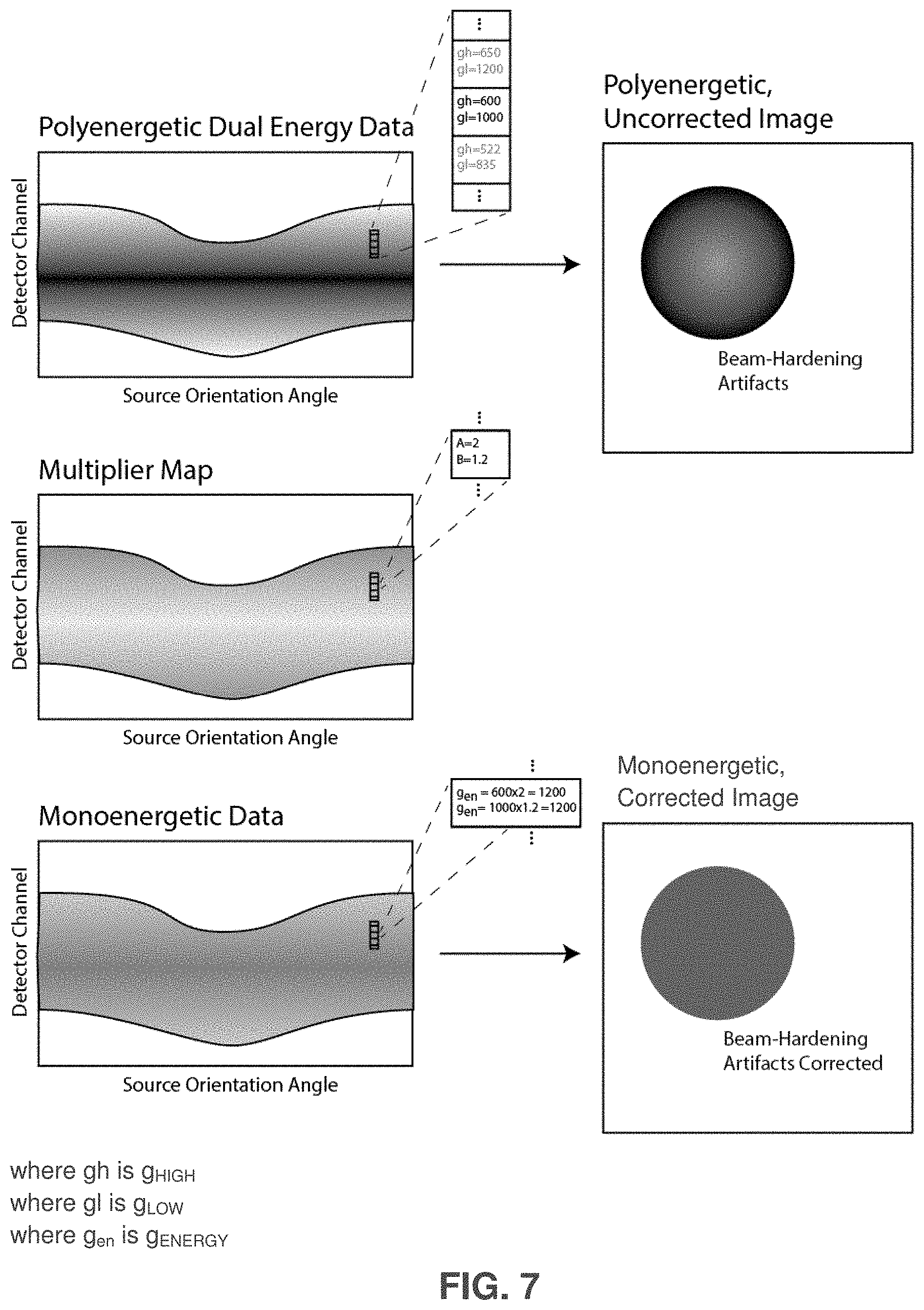
[0070] By way of example but not limitation, and looking now at FIG. 7, the top of the figure shows a representation of polychromatic dual energy data. In the field of tomographic imaging, raw data commonly takes on the form of a "sinogram" or "fanogram". The data on the left side of FIG. 7 are in sinogram format. Each "detector channel" consists of several filtered detectors. For example, with a dual energy system, there are two polyenergetic signals which are measured, g.sub.HIGH and g.sub.Low (for high and low polyenergetic ranges, respectively). The insert shows example numerical data for several detector pairs. This raw data could be turned into an uncorrected polyenergetic image using any number of industry-standard reconstruction techniques including filtered back projection. The polyenergetic image would suffer from beam-hardening image artifacts. The middle row of FIG. 7 shows an example multiplier map which transforms the raw polyenergetic data into monoenergetic data. The multiplier for each detector channel has two components, A and B, to convert the polyenergetic signals g.sub.HIGH and g.sub.Low respectively. The bottom row of FIG. 7 shows the resulting monoenergetic data. The two polyenergetic signals g.sub.HIGH and g.sub.Low are converted to a monoenergetic signal g.sub.ENERGY, where ".sub.ENERGY" may be any monoenergetic level (e.g., G.sub.160 which represents the synthetic monoenergetic sinogram at a monoenergy of 160 kev, G.sub.40 which represents the synthetic monoenergetic sinogram at a monoenergy of 40 kev, etc.). Monoenergetic data does not suffer from beam hardening artifacts when turned into an image.
[0071] Synthetic monoenergetic images also contain information on the material composition along each line of response. For example, a mathematical function rho(I.sub.HIGH, I.sub.LOW) could be used to directly determine the electron density of the material at that location (i.e., voxel).
[0072] From a computational efficiency point of view, the preferred embodiment uses a lookup table to transform the monoenergetic values at each location within the image into a material value (in this example, rho).
[0073] The underlying physical interactions which determine the attenuation of X-rays are generally characterized by Compton scattering (interacting with loosely-bound electrons) and the photoelectric effect (resonant interactions with electrons in atomic shells). Any physical property strongly dependent on the measured strength of these two kinds of interactions can be evaluated. For example, the mass-density of a material, largely dependent on the kind of atoms the material is composed of (a function of the photoelectric effect) and the number of atoms per volume (a function of the electron density), can be determined using the multiple synthetic monoenergetic images I.sub.HIGH, I.sub.LOW (which could be, for example, I.sub.160, I.sub.40).
[0074] Looking now at FIG. 8, although any number of monoenergetic datasets and images can be made, in the preferred embodiment, three monochromatic images are made. The mid-energy image optimizes the signal/noise ratio and is free of beam-hardening artifacts. The low and high-energy monochromatic images are transformed to produce an image of the material atomic composition.
Generation of Lookup Tables for Monoenergetic Sinograms
[0075] The conversion between polyenergetic sinogram data into monoenergetic sinogram data has been described above as a mathematical function, with the preferred embodiment generalized to a lookup table. The mathematical function and/or lookup table contents could be determined entirely from theoretical computations or from empirical data. For both approaches, the goal is to transform the polyenergetic signals measured at the detectors to the expected monoenergetic signals. To verify that the transform operation produces the "expected" monoenergetic signals, it is usually convenient to select test objects of simple shape and composition. In most embodiments, the "expected" values are the best scientifically derived values. In our present embodiment, these target values are obtained from data published by the National Institute of Standards and Technology (NIST), but could be obtained from any source.
[0076] Using a completely theoretical approach, one would model the spectrum of the X-ray source, and compute the expected signal level for the different kinds of filtered detectors. The signal levels for the various filtered detectors would be computed a second time assuming a monoenergetic X-ray source. Taking the ratio of the computed detector signals for the monoenergetic X-ray source to the computed detector signals for the polyenergetic source would determine the multipliers necessary to transform a measured polyenergetic signal to the target monoenergy signal.
[0077] Using a completely empirical approach would involve making measurements of many objects (with varying composition and thickness) using a standard broad-spectrum (i.e., polychromatic) X-ray source. The equivalent measurements would be acquired using a monoenergetic source. By comparing values, one could determine the multiplicative values (e.g., "A.sub.ENERGY" and "B.sub.ENERGY") to translate one set of measurements (i.e., the polychromatic measurements) to another set of measurements (i.e., the monochromatic measurements at the monoenergetic energy level "ENERGY", e.g., 160 kev, 40 kev, etc.). However, it will be appreciated that a purely empirical approach is challenging because generating monochromatic X-rays is generally difficult, and because the number measurements would be large.
[0078] A practical approach, and the preferred embodiment for the present invention, involves a predominantly theoretical approach which is fine-tuned to match empirical measurements. Known material samples with varying thicknesses can be scanned using a polyenergetic X-ray source to generate polyenergetic data, and then the polyenergetic data can be transformed to corresponding monoenergetic data using the derived lookup tables. The monoenergetic detector response to these known samples are easily computed, and can be compared with the results using the lookup process. The table values can then be adjusted to produce the correct known response.
[0079] FIGS. 9 and 10 are schematic views showing how lookup tables may be used to generate multipliers for transforming polyenergetic data sets into any number of monoenergetic data sets, each one free of beam hardening. Monoenergetic images can then be transformed into a mapping of material properties such as effective atomic number or electron density.
Generation of Lookup Tables for Determining Z.sub.effective or Other Material Properties
[0080] The conversion between monoenergetic sinogram data (i.e., g.sub.ENERGY, which could be, for example, g.sub.160, g.sub.40, etc.) and monoenergetic image data (i.e., I.sub.ENERGY, which could be, for example, I.sub.160, I.sub.40, etc.), and material properties, is a mathematical function. In the preferred embodiment, this function is reduced to a tabular form. The values within the table can be derived from the known physical properties of materials or from empirical analysis of data. In the preferred embodiment, the table is empirically derived. For example, samples of varying mean atomic number (Z.sub.effective) are scanned. The ratio of two monoenergetic images (e.g., I.sub.160, I.sub.40) is used as an index into a table which returns the Z.sub.effective value. Thus, to generate the table values, the image ratio and Z.sub.effective value are recorded for a sample material. Data from six sample materials is collected and a best fit function Z.sub.eff(Image Ratio) is determined.
Modifications
[0081] It will be appreciated that still further embodiments of the present invention will be apparent to those skilled in the art in view of the present disclosure. It is to be understood that the present invention is by no means limited to the particular constructions herein disclosed and/or shown in the drawings, but also comprises any modifications or equivalents within the scope of the invention.
* * * * *
D00000
D00001
D00002
D00003
D00004
D00005
D00006
D00007
D00008
D00009
D00010
XML
uspto.report is an independent third-party trademark research tool that is not affiliated, endorsed, or sponsored by the United States Patent and Trademark Office (USPTO) or any other governmental organization. The information provided by uspto.report is based on publicly available data at the time of writing and is intended for informational purposes only.
While we strive to provide accurate and up-to-date information, we do not guarantee the accuracy, completeness, reliability, or suitability of the information displayed on this site. The use of this site is at your own risk. Any reliance you place on such information is therefore strictly at your own risk.
All official trademark data, including owner information, should be verified by visiting the official USPTO website at www.uspto.gov. This site is not intended to replace professional legal advice and should not be used as a substitute for consulting with a legal professional who is knowledgeable about trademark law.