Thermoelectric Dehumidifying Device
Huang; Horng-Tsann ; et al.
U.S. patent application number 16/283807 was filed with the patent office on 2020-08-27 for thermoelectric dehumidifying device. The applicant listed for this patent is Norm Pacific Automation Corp.. Invention is credited to Horng-Tsann Huang, Wen-Yu Weng.
| Application Number | 20200271336 16/283807 |
| Document ID | / |
| Family ID | 1000003916438 |
| Filed Date | 2020-08-27 |


| United States Patent Application | 20200271336 |
| Kind Code | A1 |
| Huang; Horng-Tsann ; et al. | August 27, 2020 |
THERMOELECTRIC DEHUMIDIFYING DEVICE
Abstract
A thermoelectric dehumidifying device includes a case, on which a first air inlet, a second air inlet, and an air outlet are provided, and in which a thermoelectric element, a condenser, a heatsink, and a fan are provided. The thermoelectric element has a cold surface, to which the condenser is connected, and a hot surface, to which the heatsink is connected. The fan is provided between the second air inlet and the heatsink. Airflow flowing through the condenser will be cooled and dehumidified. Each fin of the condenser has a downwardly inclined bottom side, which facilitates the dripping of the water droplets condensed thereon. Said airflow will be mixed with external airflow drawn in through the second air inlet, and then blown by the fan to flow through fins of the heatsink, bringing away heat effectively and therefore improving the dehumidifying efficiency of the device.
| Inventors: | Huang; Horng-Tsann; (Hsinchu City, TW) ; Weng; Wen-Yu; (Hsinchu City, TW) | ||||||||||
| Applicant: |
|
||||||||||
|---|---|---|---|---|---|---|---|---|---|---|---|
| Family ID: | 1000003916438 | ||||||||||
| Appl. No.: | 16/283807 | ||||||||||
| Filed: | February 24, 2019 |
| Current U.S. Class: | 1/1 |
| Current CPC Class: | F24F 13/222 20130101; F24F 5/0042 20130101; F24F 3/14 20130101; F24F 2003/1446 20130101 |
| International Class: | F24F 5/00 20060101 F24F005/00; F24F 3/14 20060101 F24F003/14; F24F 13/22 20060101 F24F013/22 |
Claims
1. A thermoelectric dehumidifying device, comprising: a case, which has a first lateral surface and a second lateral surface, wherein the first lateral surface and the second lateral surface are separated by a first spacing; a horizontal length of the first lateral surface and a horizontal length of the second lateral surface are both greater than the first spacing; a thermoelectric element, which is provided between the first lateral surface and the second lateral surface, and divides a space between the first lateral surface and the second lateral surface into an upper air passage and a lower air passage, wherein an end of the upper air passage communicates with an end of the lower air passage; the thermoelectric element has a cold surface and a hot surface, wherein the cold surface is located in the lower air passage, and the hot surface is located in the upper air passage; a first air inlet, which is provided on the case, and communicates with another end of the lower air passage; a second air inlet, which is provided on the case, and communicates with the end of the upper air passage; an air outlet, which is provided on the case, and communicates with another end of the upper air passage; a condenser comprising a plurality of condensing fins, which are provided in the lower air passage, and are arranged substantially parallel to the first lateral surface in a spaced manner, wherein each of the condensing fins has a top side connected to the cold surface, and a bottom side far away from the cold surface; the bottom side of each of the condensing fins is a free side, and is inclined downward in a direction away from the first air inlet; a heatsink comprising a plurality of heat dissipation fins, which are provided in the upper air passage, and are arranged substantially parallel to the first lateral surface in a spaced manner; wherein a bottom side of each of the heat dissipation fins is connected to the hot surface; and a fan, which is fixedly provided in the upper air passage, and is located between the second air inlet and the heatsink.
2. The thermoelectric dehumidifying device of claim 1, wherein the condensing fins comprise a plurality of long condensing fins and a plurality of short condensing fins, which are provided in a staggered manner, and any two adjacent ones of the long condensing fins and the short condensing fins are spaced by a fin spacing.
3. The thermoelectric dehumidifying device of claim 2, wherein the fin spacing is between 1.5 and 3.5 mm.
4. The thermoelectric dehumidifying device of claim 2, wherein a height difference between a bottom side of each of the long condensing fins and a bottom side of each of the short condensing fin is between 2 and 4 mm.
5. The thermoelectric dehumidifying device of claim 1, wherein the case further comprises a third lateral surface and a fourth lateral surface, which are provided correspondingly; the third lateral surface and the fourth lateral surface are both respectively connected to the first lateral surface and the second lateral surface; the first air inlet and the air outlet are provided on the third lateral surface of the case.
6. The thermoelectric dehumidifying device of claim 5, wherein the second air inlet are provided on the fourth lateral surface of the case.
7. The thermoelectric dehumidifying device of claim 1, wherein the case further comprises a connecting air passage, which is a hollow passage with two open ends; the two open ends of the connecting air passage are respectively connected to the end of the upper air passage and the end of the lower air passage, so that the upper air passage communicates with the lower air passage through the connecting air passage.
8. The thermoelectric dehumidifying device of claim 7, wherein the case further comprises a plurality of first deflectors, which are provided along a wall of the connecting air passage.
9. The thermoelectric dehumidifying device of claim 1, wherein the case further comprises a second deflector, which is provided between the first air inlet and the lower air passage, and communicates the first air inlet and the lower air passage.
10. The thermoelectric dehumidifying device of claim 1, wherein the case further comprises a third deflector, which is provided between the air outlet and the upper air passage, and communicates the air outlet and the upper air passage.
11. The thermoelectric dehumidifying device of claim 1, wherein a cross-sectional area of an airflow created by the fan is substantially equal to a cross-sectional area of all of the heat dissipation fins which are arranged substantially in parallel to each other.
Description
BACKGROUND OF THE INVENTION
1. Field of the Invention
[0001] The present invention relates generally to a thermoelectric dehumidifying device, and more particularly to a slim type thermoelectric dehumidifying device which has higher dehumidifying efficiency compared to conventional thermoelectric dehumidifying devices.
2. Description of the Prior Art
[0002] A conventional dehumidifier typically uses a gas compressor to circulate refrigerant in tube passes involving a condenser and an evaporator. Due to the change in pressure, the refrigerant circulating in tube passes undergoes phase transitions between a liquid state and a gaseous state. Specifically, at the evaporator section, the refrigerant changes from a liquid state to a gaseous state through evaporation. By absorbing the heat contained within, the evaporation of the refrigerant cools the surrounding air which is drawn into the dehumidifier and flows by the outside of the tube passes. As the air temperature decreases, the moisture in the air is removed in the form of condensed water droplets. On the other hand at the condenser section, the dehumidified air, in turn, cools the compressed high-temperature refrigerant which is sent out by the gas compressor, so as to heat the dehumidified air before venting it to the outside. The moisture contained in indoor air can be removed in this way. However, this kind of dehumidifiers is usually bulky since it has to accommodate at least a gas compressor, a condenser, and an evaporator within, and therefore is not suitable for cramped usage environments such as in wardrobes, closets, or shoe cabinets.
[0003] In order to reduce the size of dehumidifiers, some manufacturers replace gas compressors with thermoelectric cooling modules, as disclosed in the published Japanese patent application No. JPH06-163997, which can be referred to in FIG. 1. Said published patent application discloses a thermoelectric device 21, which includes a thermoelectric cooling module containing N-type semiconductors 24 and P-type semiconductors 26 sequentially connected and fixedly disposed between two thermoelectric conductors 28, each of which is located on one of two opposite end surfaces. The sequential connection between the N-type semiconductors 24 and the P-type semiconductors 26 is capable of urging the energy carriers in electric current to move toward the same thermoelectric conductor 28 on one of the end surfaces. Therefore, once the thermoelectric cooling module is supplied with electric current, the energy carriers will accumulate at the same thermoelectric conductor 28 on one end surface, heating the thermoelectric conductor 28 on said end surface and making it become a hot surface. At the same time, the other thermoelectric conductor 28 on the other end surface correspondingly becomes a cold surface, for the energy carriers in the electric current all move in a direction away from this end surface. In the design of the disclosed dehumidifier, the air flowing into the dehumidifier is cooled by the cold surface of the thermoelectric cooling module first, where the moisture in the air gets removed as being condensed into water droplets on the cold surface. Before the cooled and dehumidified air is vented to the outside, it flows by the hot surface of the thermoelectric cooling module to bring away heat from there.
[0004] When the thermoelectric cooling module is not supplied with electricity, its two end surfaces would naturally have equal temperatures. After being provided with electric current, the energy on one end surface is gradually transferred to the other one end surface by the energy carriers in the electric current, whereby the end surfaces respectively become a cold surface and a hot surface as described above. Along with the process that the temperature at the cold surface approaches the temperature suitable for condensing moisture, there is more and more energy being reduced from the cold surface side and accumulated at the hot surface, only cooled and dehumidified air has a smaller volume, and therefore can only take away limited heat energy with it. Due to this reason, when the cold surface and the hot surface have a great temperature difference in between, the cold surface may not be able to be further cooled since only limited heat energy can be transferred to the hot surface. As a result, the cold surface naturally has a poorer performance in condensing moisture. To solve this problem, said published patent application discloses a design that introduces an airflow into the dehumidifier from outside before the cooled and dehumidified air reaches the hot surface. The combined airflow formed by mixing the cooled airflow and the outside airflow has a larger volume, so that the airflow utilized to bring away the heat energy at the hot surface can have a larger volume as well. More details about the design of said published patent application: an opening 31 is provided where the airflow has yet to reach the hot surface, and a cross-flow fan 29 is provided at an air outlet, through which the airflow is vented after passing through the hot surface. The cross-flow fan 29 provides an air-drawing effect, whereby the outside air can be pulled into the dehumidifier through the opening 31 to become a second airflow, which can be mixed with the cooled and dehumidified air before passing through the hot surface, whereby to bring away more heat energy at the hot surface. The air-drawing effect of the cross-flow fan 29 can create smooth and steady airflow, which has roughly constant cross-sectional shape and area. Hence, the mixed airflow which is formed by mixing the second airflow and the cooled airflow by the drawing of the cross-flow fan 29 is smooth and steady. However, when such mixed airflow passes by the hot surface, only the heat energy at locations on the hot surface having contact with the cross-section of the mixed airflow can be taken away, so that the heat dissipation effect of the hot surface is still rather limited. If the heat dissipation effect of the hot surface is limited, so is the cooling effect of the cold surface of the thermoelectric cooling module, leading to a poor moisture-condensing performance on the cold surface, which hinders the dehumidifying efficiency.
[0005] In order to increase the areas on the cold surface and on the hot surface contacting with the airflow, the above-mentioned published patent application further provides multiple fins 23 connected to the cold surface of the thermoelectric cooling module. A top of each fin 23 is connected to the cold surface, while a bottom thereof is a free side extending downward. The hot surface of the thermoelectric cooling module also has multiple fins 23 connected thereto. When the airflow drawn into the dehumidifier passes by the fins connected to the cold surface, the air temperature will be decreased through the abundant contact with the fins 23, so that the moisture in the airflow will condense on the fins 23 into water droplets. These droplets will slide down along the fins 23 toward the free side due to their own weight, and eventually fall off from the fins. However, a water droplet would not slide too quickly on the fin 23 where it condenses onto, especially when it is light in weight and located near the top side of the fin 23. Being light in weight, such a water droplet can only slide slowly. It is only until the water droplet, in its slow-paced sliding movement, happens to bump into another water droplet which is also condensed on the same fin and merge into a heavier water droplet, the sliding movement can be quickened. During the slow-paced sliding movement of the water droplets, the airflow keeps passing by the fins 23. However, those water droplets prevent the airflow from contacting the portions of the fins which are directly covered by the droplets, which hinders the cooling of the airflow, and therefore interferes with the water droplet from further condensing on the fins 23. As a result, the dehumidifying efficiency of the airflow drawn into the dehumidifier is still not satisfying.
SUMMARY OF THE INVENTION
[0006] In view of the above, one aspect of the present invention is to provide a thermoelectric dehumidifying device, which is a slim cuboid with the air inlet/outlet provided on the short lateral surface of the case, and therefore is adapted to be placed in a cramped space for dehumidification. By providing the fan at a right position, the heat dissipation effect of the hot surface of the thermoelectric element could be improved, so that the temperature at the cold surface could be well-maintained to provide a better dehumidifying capability. Furthermore, the bottom of each condensing fin is inclined downward in line with the flowing direction of the airflow, and the bottoms of any two adjacent condensing fins are not at the same height, so that the sliding and dropping of the water droplets condensed on the condensing fins could be accelerated, which could improve the efficiency for the water droplets on the condensing fins to fall off. As a result, the overall dehumidifying efficiency of the thermoelectric dehumidifying device could be further enhanced.
[0007] The present invention provides a thermoelectric dehumidifying device, which includes a case, a thermoelectric element, a first air inlet, a second air inlet, an air outlet, a condenser, a heatsink, and a fan. The case has a first lateral surface and a second lateral surface, wherein the first lateral surface and the second lateral surface are separated by a first spacing. A horizontal length of the first lateral surface and a horizontal length of the second lateral surface are both greater than the first spacing. The thermoelectric element is provided between the first lateral surface and the second lateral surface, and divides a space between the first lateral surface and the second lateral surface into an upper air passage and a lower air passage, wherein an end of the upper air passage communicates with an end of the lower air passage. The thermoelectric element has a cold surface and a hot surface, wherein the cold surface is located in the lower air passage, and the hot surface is located in the upper air passage. The first air inlet is provided on the case, and communicates with another end of the lower air passage. The second air inlet is provided on the case, and communicates with the end of the upper air passage. The air outlet is provided on the case, and communicates with another end of the upper air passage. The condenser includes a plurality of condensing fins, which are provided in the lower air passage, and are arranged substantially parallel to the first lateral surface in a spaced manner, wherein each of the condensing fins has a top side connected to the cold surface, and a bottom side far away from the cold surface. The bottom side of each of the condensing fins is a free side, and is inclined downward in a direction away from the first air inlet. The heatsink includes a plurality of heat dissipation fins, which are provided in the upper air passage, and are arranged substantially parallel to the first lateral surface in a spaced manner; wherein a bottom side of each of the heat dissipation fins is connected to the hot surface. The fan is fixedly provided in the upper air passage, and is located between the second air inlet and the heatsink.
[0008] By utilizing the difference between the horizontal lengths of the opposite lateral surfaces of the case and the first spacing between the opposite lateral surfaces, and by providing the air outlet and inlets between the first spacing, the thermoelectric dehumidifying device could be a slim cuboid, and therefore is adapted to be placed in a cramped space for dehumidification. Furthermore, the fan provided between the second air inlet and the heatsink could push the turbulent airflow, which is mixed by the outside airflow and the dehumidified cold airflow, to flow between the heat dissipation fins, which could effectively bring away the heat energy on the heat dissipation fins and the hot surface of the thermoelectric cooling module, whereby to maintain the low temperature at the condensing fins and to ensure the dehumidifying capability achieved by condensing water droplets. In addition, the bottom side of each of the condensing fins is designed to be inclined downward in line with the flowing direction of the airflow, which could urge the water droplets condensed on each of the condensing fins to slide in the downwardly inclined direction. Moreover, a droplet could easily contact and combine with another droplet condensed on the same or the adjacent condensing fin to form a more massive droplet, whereby the dropping of water droplets could be sped up. Therefore, the dehumidifying effect for the airflow which enters the dehumidifying device could be improved.
[0009] These and other objectives of the present invention will no doubt become obvious to those of ordinary skill in the art after reading the following detailed description of the preferred embodiment that is illustrated in the various figures and drawings.
BRIEF DESCRIPTION OF THE DRAWINGS
[0010] FIG. 1 is a rough schematic view of the dehumidifying device disclosed in the published patent application JPH06-163997.
[0011] FIG. 2 is a perspective view of the thermoelectric dehumidifying device of the present invention.
[0012] FIG. 3 is a perspective view of the thermoelectric dehumidifying device of the present invention seen from another angle.
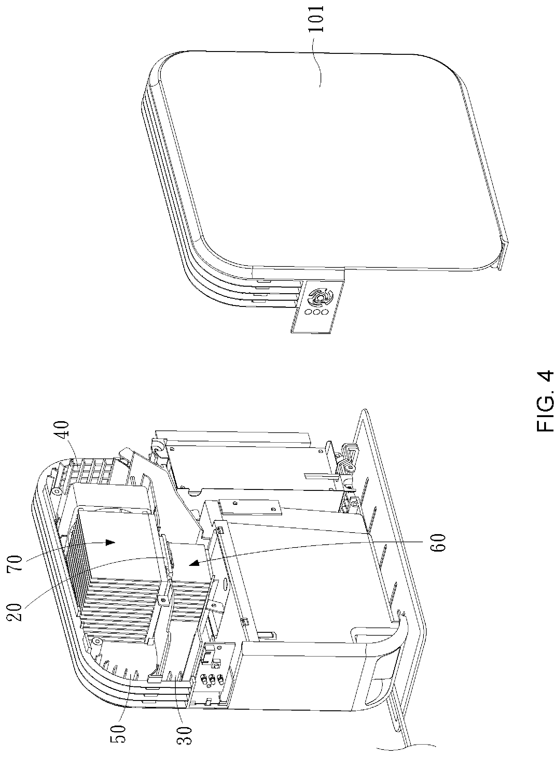
[0013] FIG. 4 is a perspective view of the inner arrangements of the thermoelectric dehumidifying device of the present invention.
[0014] FIG. 5 is a 2D schematic view showing the upper air passage, the lower air passage, and the connecting air passage of the thermoelectric dehumidifying device of the present invention.
[0015] FIG. 6 is a 2D schematic view showing the inner arrangements of the thermoelectric dehumidifying device of the present invention.
[0016] FIG. 7 is a perspective view showing how the thermoelectric element, the heat dissipation fin, and the condensing fin of the thermoelectric dehumidifying device of the present invention are connected.
[0017] FIG. 8 is a schematic view showing the comparison between the cross-sectional area of the airflow produced by the fan and the cross-sectional area of the heat dissipation fin in the thermoelectric dehumidifying device of the present invention.
[0018] FIG. 9 is a schematic view showing how the water droplets on the condensing fin of the thermoelectric dehumidifying device of the present invention may contact another droplet to combine and run down.
[0019] FIG. 10 is an enlarged schematic view showing part of FIG. 9.
[0020] FIG. 11 is a rough schematic view showing the flow path of the airflow of the thermoelectric dehumidifying device of the present invention.
[0021] FIG. 12 is a 2D schematic view showing the inner arrangements of the thermoelectric dehumidifying device of another embodiment of the present invention.
DETAILED DESCRIPTION
[0022] As shown in FIG. 2 to FIG. 8, a thermoelectric dehumidifying device 100 of the present invention includes a case 10, a thermoelectric element 20, a first air inlet 30, a second air inlet 40, an air outlet 50, a condenser 60, a heatsink 70, and a fan 80, wherein the first air inlet 30, the second air inlet 40, and the air outlet 50 are provided on the case 10, while the thermoelectric element 20, the condenser 60, the heatsink 70, and the fan 80 are provided in the case 10.
[0023] The case 10 includes a first lateral surface 101, a second lateral surface 102, a third lateral surface 103, and a fourth lateral surface 104, wherein the first lateral surface 101 and the second lateral surface 102 are separated by a first spacing d1. A horizontal length 1011 of the first lateral surface 101 and a horizontal length 1021 of the second lateral surface 102 are both greater than the first spacing d1. The third lateral surface 103 and the fourth lateral surface 104 are provided between the first lateral surface 101 and the second lateral surface 102, and are respectively connected to the first lateral surface 101 and the second lateral surface 102. In the current embodiment, the ratio of the horizontal length 1011 (1021) to the first spacing d1 is 3:1 to 4:1, so that the case 10 is a slightly slim cuboid as a whole, which is adapted to be placed in cramped spaces such as in wardrobes, closets, or shoe cabinets. The air outlet 50 and the first air inlet 30 are vertically provided on the third lateral surface 103, while the second air inlet 40 is provided on the fourth lateral surface 104.
[0024] As shown in FIG. 2 to FIG. 6, the thermoelectric element 20 is provided between the first lateral surface 101 and the second lateral surface 102. A space surrounded by the first lateral surface 101, the second lateral surface 102, the third lateral surface 103, and the fourth lateral surface 104 is divided into an upper air passage 105 and a lower air passage 106 by the thermoelectric element 20, wherein the upper air passage is above and adjacent to the lower air passage. An end of the upper air passage 105 and an end of the lower air passage 106 are respectively connected to one of two ends of a connecting air passage 107. A plurality of first deflectors 108 are provided along a surrounding wall of the connecting air passage 107, so that the connecting air passage 107 is a hollow passage with two open ends, wherein one of the open ends is connected to the end of the upper air passage 105, and the other one of the open ends is connected to the end of the lower air passage 106. In this way, the upper air passage 105 and the lower air passage 106 can communicate with each other, and airflow can be guided to flow to the upper air passage 105 from the lower air passage 106. In the current embodiment, the connecting air passage 107 is provided near the fourth lateral surface 104.
[0025] A second deflector 109 is provided between the first air inlet 30 on the third lateral surface 103 and another end of the lower air passage 106, whereby to communicate the first air inlet 30 and the lower air passage 106, so that airflow can be guided to flow to the lower air passage 106 from the first air inlet 30. A third deflector 110 is provided between the air outlet 50 on the third lateral surface 103 and another end of the upper air passage 105, whereby to communicate the air outlet 50 and the upper air passage 105, so that airflow can be guided to flow to the air outlet 50 from the upper air passage 105.
[0026] The thermoelectric element 20 has a cold surface 201 and a hot surface 202, wherein the cold surface 201 is located in the lower air passage 106, and the hot surface 202 is located in the upper air passage 105. As shown in FIG. 7, the condenser 60 includes a plurality of long condensing fins 601 and a plurality of short condensing fins 602. The long condensing fins 601 and the short condensing fins 602 are provided in the lower air passage 106, and are arranged substantially parallel to the first lateral surface 101 in a manner that the long condensing fins 601 and the short condensing fins 602 are staggered. Each adjacent pair of the long condensing fins 601 and the short condensing fins 602 is spaced by a fin spacing d2, which is between 1.5 and 3.5 mm in the current embodiment. A top side 601a of each of the long condensing fins 601 and a top side 602a of each of the short condensing fins 602 are connected to the cold surface 201 of the thermoelectric element 20, whereby to transfer the heat of the cold surface 201 to the long condensing fins 601 and the short condensing fins 602. In the current embodiment, the top sides 601a of the long condensing fins 601 and the top sides 602a of the short condensing fins 602 are integrally connected together to be connected, or affixed, to the cold surface 201. A bottom side 601b of each of the long condensing fins 601 and a bottom side 602b of each of the short condensing fins 602 are both a free side, and the bottom sides 601b, 602b of each two adjacent condensing fins 601, 602 have a height difference d3 in between. In the current embodiment, the height difference d3 is between 2 and 4 mm. The heatsink 70 includes a plurality of heat dissipation fins 701, wherein the heat dissipation fins 701 are provided in the upper air passage 105, and are arranged substantially parallel to the first lateral surface 101 in a spaced manner. Furthermore, the bottom side 701a of each of the heat dissipation fins 701 is connected to the hot surface 202 of the thermoelectric element 20. In the current embodiment, the bottom sides 701a of the heat dissipation fins 701 are integrally connected together to be connected, or affixed, to the hot surface 202, whereby to transfer the heat of the hot surface 202 to the heat dissipation fins 701.
[0027] As both shown in FIG. 6 and FIG. 8, the fan 80 is fixedly provided in the upper air passage 105 near the fourth lateral surface 104, and is between the second air inlet 40 and the heatsink 70. A cross-sectional area of the airflow created by the fan 80 is roughly equal to a cross-sectional area of the whole set of the heat dissipation fins 701 which are arranged in parallel, so that the airflow created by the fan 80 could pass by each one of the heat dissipation fins 701 in a just-right way. In other words, the airflow could be well utilized with no excessive energy waste.
[0028] In the current embodiment, as shown in FIG. 7, the mutually connected top sides 601a, 602a of the long condensing fins 601 and the short condensing fins 602 of the condenser 60 can be integrally made through aluminum extrusion. Furthermore, the long condensing fins 601 and the short condensing fins 602 are arranged in a parallel and staggered manner, so that the heat of the cold surface 201 can be transferred to the long condensing fins 601 and the short condensing fins 602 through close connection between the top sides 601a, 602a and the cold surface 201. Similarly, the mutually connected bottom sides 701a of the heatsink 70 can also be integrally made through aluminum extrusion, wherein the heat dissipation fins 701 are arranged in a parallel and spaced manner, whereby the heat on the hot surface 202 can be transferred to the heat dissipation fins 701 through the close connection between the bottom sides 701a and the hot surface 202.
[0029] In the current embodiment, the bottom side 601b of each of the long condensing fins 601 and the bottom side 602b of each of the short condensing fins 602 are both gradually inclined in a direction away from the first air inlet 30, as shown in FIG. 6. In other words, the bottom side 601b of each of the long condensing fins 601 and the bottom side 602b of each of the short condensing fins 602 are inclined downward in line with the flowing direction of the airflow. There are various ways to implement said inclined arrangements. For example, the bottom sides 601b of the long condensing fins 601 and the bottom sides 602b of the short condensing fins 602 can be made as inherently inclined, or those bottom sides 601 can be made as non-inclined, and the long condensing fins 601 and the short condensing fins 602 are connected to the cold surface 201 at an inclined angle instead. Alternatively, the long condensing fins 601 and the short condensing fins 602 can be made with a non-inclined bottom side, and are connected to the thermoelectric element 20 in a non-inclined manner, but the thermoelectric dehumidifying device 100 itself is inclinedly provided in the case 10. The means of implementation described here are not limitations of the present invention, as long as the bottom sides 601b of the long condensing fins 601, and the bottom sides 602b of the short condensing fins 602 can be rendered as downwardly inclined.
[0030] As shown in FIG. 5 to FIG. 11, a humid airflow A entering the case 10 through the first air inlet 30 would be guided by the second deflector 109 to flow toward the lower air passage 106. When the airflow A enters the condenser 60 installed in the lower air passage 106, the condensing fins 601, 602 and the airflow A would have energy exchange as the relatively warm airflow A meets the relatively cold condensing fins 601, 602, whereby the temperature of the airflow A would gradually decrease. Once the temperature decreases to a specific temperature, the moisture contained in the airflow A reaches saturation, and would condense if the temperature decreases any further. The temperature at this time point is called dew point temperature. The moisture contained in the airflow A would condense on the condensing fins 601, 602 as small water droplets, which would be moved by the airflow A to slide down and merge with each other along the downwardly inclined bottom sides 601b, 602b of the condensing fins 601, 602 in a direction toward the fourth lateral surface 104, and would eventually leave the condenser 60 by falling off from the condensing fins 601, 602, whereby the moisture in the airflow A would be removed. After the process, the airflow A becomes a dehumidified and cooled airflow B, which would then flow into the upper air passage 105 along the connecting air passage 107 connected to the lower air passage 106, and would be drawn by the fan 80 to flow toward the heatsink 70 installed in the upper air passage 105. Since the fan 80 is installed between the second air inlet 40 and the heatsink 70, the fan 80 would also pull in an external airflow C from outside while drawing the cooled airflow B. As a result, the cooled airflow B and the external airflow C would be mixed to become a mixed airflow D which is blown to the heatsink 70. When the mixed airflow D flows through the heatsink 70, the mixed airflow D would contact and pass by a surface of each of the heat dissipation fins 701, whereby to bring away the heat energy on the heat dissipation fins 701. The temperature of the mixed airflow D could be increased in this way, so that the mixed airflow D would become a warm airflow E, which would then be vented through the air outlet 50 provided on the third lateral surface 103.
[0031] In the current embodiment, the bottom side 601b of each of the long condensing fins 601 and the bottom side 602b of each of the short condensing fins 602 are inclined downward in the direction away from the first air inlet 30, as shown in FIG. 9 and FIG. 10. When the airflow A contacts the condensing fins 601, 602 and condenses thereon, the weight of water droplets would drive the water droplets to slide down along the condensing fins 601, 602. Furthermore, the water droplets would be also pushed by the flowing of the airflow A to run along the inclined bottom sides 601b, 602b of the condensing fins 601, 602. With such design, the water droplets would be urged to move in a downward direction away from the first air inlet 30 and toward the fourth lateral surface 104. When the water droplets on the short condensing fins 602 reaches the bottom sides 602b thereof, they will contact the water droplets on the adjacent long condensing fins 601; two contacted water droplets would combine into a larger water droplet due to the effect of surface tension, and this combined, larger water droplet could slide down along the long condensing fin 601 at an accelerated pace in a downward direction toward the fourth lateral surface 104. Once the water droplets reach the bottom sides of the long condensing fins 601, they would then fall off the condensing fins 601, 602 in no time. As a result, the efficiency for the condensing fins 601, 602 to condense water droplets could be improved. More specifically, once water droplets leave the condenser 60, they would no longer consume the cooling ability of the thermoelectric element 20, whereby the condenser 60 could keep exerting its cooling effect, enhancing the dehumidifying efficiency for the airflow A. With the staggered design between the long and short condensing fins 601, 602, the water droplets condensed on the short condensing fins 602 would be more likely to be gathered onto the long condensing fins 601. For example, if there are 6 short condensing fins staggered with 5 long condensing fins (i.e., 11 condensing fins in total), the condensed water drops would be more likely to converge onto the 5 long condensing fins (roughly the half of the total number of the condensing fins) at bottom sides, which would facilitates the water droplets to grow, and would accelerates the sliding and falling of the water droplets.
[0032] It is worth mentioning that, during the sliding of a water droplet, it could also combine with another water droplet on the adjacent condensing fin to form a larger water droplet when it is possible, even if it is yet to arrive at the corresponding bottom side 601b, 602b. The subsequent sliding movement could be therefore accelerated, whereby the water droplets could quickly leave the condensing fins 601, 602.
[0033] The table below shows the dehumidifying ability for thermoelectric dehumidifying devices implemented based on the present invention, each of which has different condensing fin spacing d2 and different height difference d3 between any two adjacent condensing fins. The results are measured in the same conditions (specifically, the devices are operated in rooms with the same interior space, the same indoor humidity, and the same room temperature), and are expressed by the weight of the extracted water per hour. In these tests, the external volume of the condenser 60 (which is about 40 mm long, 40 mm wide, and 38 mm high) and the thickness of each condensing fin (which is between 1.0 and 1.3 mm) stay unchanged. Hence, with a greater fin spacing d2, there will be fewer condensing fins. As for the height difference d3, which is a shortened amount for the short condensing fins 602 relative to the long condensing fins 601, we take 0 to 5 mm for testing. In addition, the average height of the condensing fins in each test model is all the same (for example, when d3=2 mm, each long condensing fin is 39 mm and each short condensing fin is 37 mm, so the average height is 38 mm; when d3=0, each long condensing fin and each short condensing fin are both 38 mm, which also have a 38 mm average height). With this requirement, the total surface area of the condensing fins in each test model will be equal, which excludes unnecessary variables for our comparison. This table should be able to show how the changes in the fin spacing d2 and the height difference d3 between each two adjacent condensing fins 601, 602 would affect the dehumidifying effect.
TABLE-US-00001 Fin spacing d2 (mm) (number of fins) Change in Amount of extracted 1.5 2 2.5 3 3.5 4 height of fins water (gram/hour) (16) (13) (11) (10) (9) (8) (Height of two (38/38) 0 14.6 15.0 15.3 15.0 14.5 14.1 adjacent fins) (39/37) 2 14.8 15.3 15.8 15.4 15.0 14.1 height difference (39.5/36.5) 3 15.2 15.9 16.4 16.0 15.4 14.3 d3 (mm) (40/36) 4 15.0 15.6 16.3 15.8 15.2 14.2 (40.5/35.5) 5 14.8 15.4 16.0 15.6 14.8 14.0
[0034] In the above experiments, the total number of condensing fins varies due to different fin spacing. Among all test models, those having a nonzero height difference d3 between two adjacent condensing fins are able to extract more water from the ambient air in comparison to the one having condensing fins of the same length. The test models with a height difference d3 of 2 to 4 mm between two adjacent condensing fins particularly have good performance. In other words, the height difference d3 between two adjacent condensing fins is preferably set as 2 to 4 mm for the best moisture condensing efficiency.
[0035] Also, in the current embodiment, the fan 80 is provided between the second air inlet 40 and the heatsink 70, as shown in FIG. 8, which means the fan 80 is located at where the mixed airflow D is yet to contact the heatsink 70. Therefore, the mixed airflow D would be pushed by the fan 80 to pass between the heat dissipation fins 701. When the mixed airflow D passes by, all of the heat dissipation fins 701 will be contacted for heat exchange at the same time. Creating airflow by drawing and by pushing are different things that the airflow created by the former means would be steady and smooth, while the airflow created by the latter means would be turbulent, for such airflow would be moved by the rotation of the blades of the fan. That is to say, if the mixed airflow D passes between the heat dissipation fins 701 by being drawn, then the resultant steady airflow would only have limited contact areas with the heat dissipation fins 701, and therefore only a limited part of the heat energy on the heat dissipation fins could be brought away, which would lead to a poor heat dissipation effect. However, in the current embodiment, the mixed airflow would be pushed, instead of being drawn, by the fan 80, and the resultant mixed airflow D would be turbulent, and would have larger contact areas with the heat dissipation fins 701, whereby to bring away more heat energy thereon. In this way, the heat dissipation effect of the heat dissipation fins 70 and the hot surface 202 of the thermoelectric element 20 could be enhanced, so that the cold surface 201 of the thermoelectric element 20 could be maintained at some low temperature suitable for condensing moisture, and the dehumidifying efficiency could be improved as well.
[0036] Another embodiment of the present invention is shown in FIG. 12, which is different from the previous embodiment by the number of the thermoelectric elements 20 provided in the case 10. In other words, there can be more than one thermoelectric element 20 connected in series or in parallel. In the current embodiment, there are two thermoelectric elements 20 connected in series, wherein the two cold surfaces 201 of the thermoelectric elements 20 are connected to the condenser 60, and the two hot surfaces 202 of the thermoelectric elements 20 are connected to the heatsink 70. With such design, there can be two thermoelectric elements 20 used for dehumidification. Needless to say, there also can be more than one condenser 60 and more than one heatsink 70. Furthermore, their fins can be appropriately staggered in the flowing direction of the airflow, whereby to facilitate a good heat dissipation effect for the airflow which passes through.
[0037] With the structures described above, the benefits provided by the present invention would include: [0038] (1) With the downwardly inclined design of the bottom side of each condensing fin, once the moisture in the airflow which enters the thermoelectric dehumidifying device condenses on the condensing fins into water droplets, these water droplets would quickly slide downward and toward the fourth lateral surface, i.e., in the flowing direction of the airflow and the inclined direction. Meanwhile, by taking advantage of the height difference between the bottom sides of every two adjacent condensing fins, the water droplets on adjacent condensing fins could contact and combine with each other, whereby the water droplets would be more likely to gather on the long condensing fin, forming larger water droplets, which could quickly fall off from the condensing fins. Since water droplets could slide down on the condensing fin at a fast pace, any location on one condensing fin which has a water droplet condensed thereon would soon be able to contact the airflow again, and another water droplet could be condensed at the same location shortly afterward. In this way, the condensing efficiency could be improved, whereby to enhance the dehumidifying effect applied to the airflow passing by the condensing fins. [0039] (2) The dehumidified and cooled airflow could be mixed with an external airflow to become a mixed airflow, which would be pushed by the fan to pass through the heatsink and get vented through the air outlet. Since the mixed airflow is moved by the pushing of the fan, a cross-section of the mixed airflow would neither have a static area nor have a constant shape. In other words, the mixed airflow would be a turbulent airflow. Therefore, when the mixed airflow passes through the heatsink, it could have larger contact areas with the heat dissipation fins, which could effectively bring away the heat energy on the heat dissipation fins. In the condition that each heat dissipation fin has a better heat dissipation effect, the temperature of the hot surface of the thermoelectric element connected to the heatsink could be easily lowered, so that the energy on the cold surface of the thermoelectric element could be further transferred to the hot surface. In this way, the cold surface could be maintained to have a low temperature, and the condensing fins could consequently have a low temperature as well, which would facilitate the condensation on the condensing fins. [0040] (3) The thermoelectric dehumidifying device in the present invention has wide lateral surfaces and narrow lateral surfaces, and the air inlets/outlet are provided on the narrow lateral surfaces. With such design, the thermoelectric dehumidifying device would be adapted to be placed in a cramped indoor space. In other words, thermoelectric dehumidifying devices designed based on the present invention could be implemented in slim types.
[0041] Those skilled in the art will readily observe that numerous modifications and alterations of the device and method may be made while retaining the teachings of the invention. Accordingly, the above disclosure should be construed as limited only by the metes and bounds of the appended claims.
* * * * *
D00000
D00001
D00002
D00003
D00004
D00005
D00006
D00007
D00008
D00009
D00010
XML
uspto.report is an independent third-party trademark research tool that is not affiliated, endorsed, or sponsored by the United States Patent and Trademark Office (USPTO) or any other governmental organization. The information provided by uspto.report is based on publicly available data at the time of writing and is intended for informational purposes only.
While we strive to provide accurate and up-to-date information, we do not guarantee the accuracy, completeness, reliability, or suitability of the information displayed on this site. The use of this site is at your own risk. Any reliance you place on such information is therefore strictly at your own risk.
All official trademark data, including owner information, should be verified by visiting the official USPTO website at www.uspto.gov. This site is not intended to replace professional legal advice and should not be used as a substitute for consulting with a legal professional who is knowledgeable about trademark law.