Oil Distributor
De Laet; Wim ; et al.
U.S. patent application number 16/651359 was filed with the patent office on 2020-08-27 for oil distributor. The applicant listed for this patent is ZF Friedrichshafen AG, ZF Wind Power Antwerpen N.V.. Invention is credited to Wim De Laet, Pieter-Jan Francis, Bart Geudens.
| Application Number | 20200271214 16/651359 |
| Document ID | / |
| Family ID | 1000004827087 |
| Filed Date | 2020-08-27 |

| United States Patent Application | 20200271214 |
| Kind Code | A1 |
| De Laet; Wim ; et al. | August 27, 2020 |
OIL DISTRIBUTOR
Abstract
The invention relates to an arrangement, comprising a first oil line (121, 123), a second oil line (105), a third oil line (107), and a cavity (103, 111); wherein the first oil line (121, 123), the second oil line (105), and the third oil line each have a mouth into the cavity (103, 111). The arrangement comprises a plate (113) having a continuous first hole (115) and a continuous second hole (117), wherein the plate (113) is arranged in the cavity (103, 111) in such a way that the plate covers the mouths of the second oil line (105) and the third oil line (107). The first hole (115) connects the second oil line (105) and the cavity (103) to one another in a fluid-conducting manner; wherein the second hole (117) connects the third oil line (107) and the cavity (103, 111) to one another in a fluid-conducting manner
| Inventors: | De Laet; Wim; (Antwerp, BE) ; Geudens; Bart; (Retie, BE) ; Francis; Pieter-Jan; (Geetbets, BE) | ||||||||||
| Applicant: |
|
||||||||||
|---|---|---|---|---|---|---|---|---|---|---|---|
| Family ID: | 1000004827087 | ||||||||||
| Appl. No.: | 16/651359 | ||||||||||
| Filed: | August 29, 2018 | ||||||||||
| PCT Filed: | August 29, 2018 | ||||||||||
| PCT NO: | PCT/EP2018/073204 | ||||||||||
| 371 Date: | March 27, 2020 |
| Current U.S. Class: | 1/1 |
| Current CPC Class: | F16H 57/0424 20130101; F16H 57/031 20130101; F16H 57/0423 20130101 |
| International Class: | F16H 57/04 20060101 F16H057/04; F16H 57/031 20060101 F16H057/031 |
Foreign Application Data
| Date | Code | Application Number |
|---|---|---|
| Sep 29, 2017 | DE | 10 2017 217 377.7 |
Claims
1. An arrangement, comprising: a first oil line; a second oil line; a third oil line; a cavity; and a plate having a continuous first hole and a continuous second hole, wherein the first oil line, the second oil line and the third oil line each have a mouth in the cavity, wherein the plate is arranged in the cavity in such a way that it covers the mouths of the second oil line and the third oil line; wherein the first hole connects the second oil line and the cavity to each other in a fluid-conducting manner; and wherein the second hole connects the third oil line and the cavity to each other in a fluid-conducting manner.
2. The arrangement according to claim 1, further comprising: a component having a recess; and a cover that covers the recess, wherein the mouths of the second oil line and the third oil line lie in the recess.
3. The arrangement according to claim 2, wherein the recess has a flat face, wherein the mouths of the second oil line and the third oil line lie in the flat face; and wherein the plate is fixed to a surface.
4. The arrangement according to claim 2, wherein the first oil line passes through the cover.
5. The arrangement according to claim 3, wherein the plate and the face are congruent, and wherein the flat face is not rotationally symmetrical.
6. The arrangement according to claim 1, further comprising: an oil circuit; wherein the first oil line, the second oil line, the third oil line and the cavity are integrated into the oil circuit such that oil is configured to be introduced into the cavity through the first oil line and discharged from the cavity through the second oil line and the third oil line.
7. A gearbox with an arrangement according to claim 2; wherein a housing of the gearbox forms the component.
Description
CROSS REFERENCE TO RELATED APPLICATIONS
[0001] This application is a U.S. National Stage Application under 35 U.S.C. .sctn. 371 of International Application No. PCT/EP2018/073204 filed on Aug. 29, 2018, and claims benefit to German Patent Application No. DE 10 2017 217 377.7 filed on Sep. 29, 2017. The International Application was published in German on Apr. 4, 2019 as WO 2019/063234 A1 under PCT Article 21(2).
FIELD
[0002] The invention relates to an arrangement having a first oil line, a second oil line, a third oil line, and a cavity, wherein the first oil line, the second oil line, and the third oil line each have a mouth in the cavity.
BACKGROUND
[0003] Solutions with diaphragms are known from the prior art for branching a line for supplying oil in a gearbox. In this case, an oil-supplying line branches into a plurality of supply lines. Diaphragms are embedded in the supply lines in order to achieve a defined distribution of the oil.
[0004] Oil lines in a gearbox housing are usually introduced through bores. With regard to the production costs, bores with the same diameter are to be sought. However, this entails the risk that the diaphragms will be incorrectly installed. Moreover, the manufacture and assembly of the diaphragms is associated with increased costs.
SUMMARY
[0005] In an embodiment, the present invention provides an arrangement, comprising a first oil line, a second oil line, a third oil line, a cavity, and a plate having a continuous first hole and a continuous second hole. The first oil line, the second oil line and the third oil line each have a mouth in the cavity. The plate is arranged in the cavity in such a way that it covers the mouths of the second oil line and the third oil line. The first hole connects the second oil line and the cavity to each other in a fluid-conducting manner. The second hole connects the third oil line and the cavity to each other in a fluid-conducting manner.
BRIEF DESCRIPTION OF THE DRAWINGS
[0006] The present invention will be described in even greater detail below based on the exemplary figures. The invention is not limited to the exemplary embodiments. All features described and/or illustrated herein can be used alone or combined in different combinations in embodiments of the invention. The features and advantages of various embodiments of the present invention will become apparent by reading the following detailed description with reference to the attached drawings which illustrate the following:
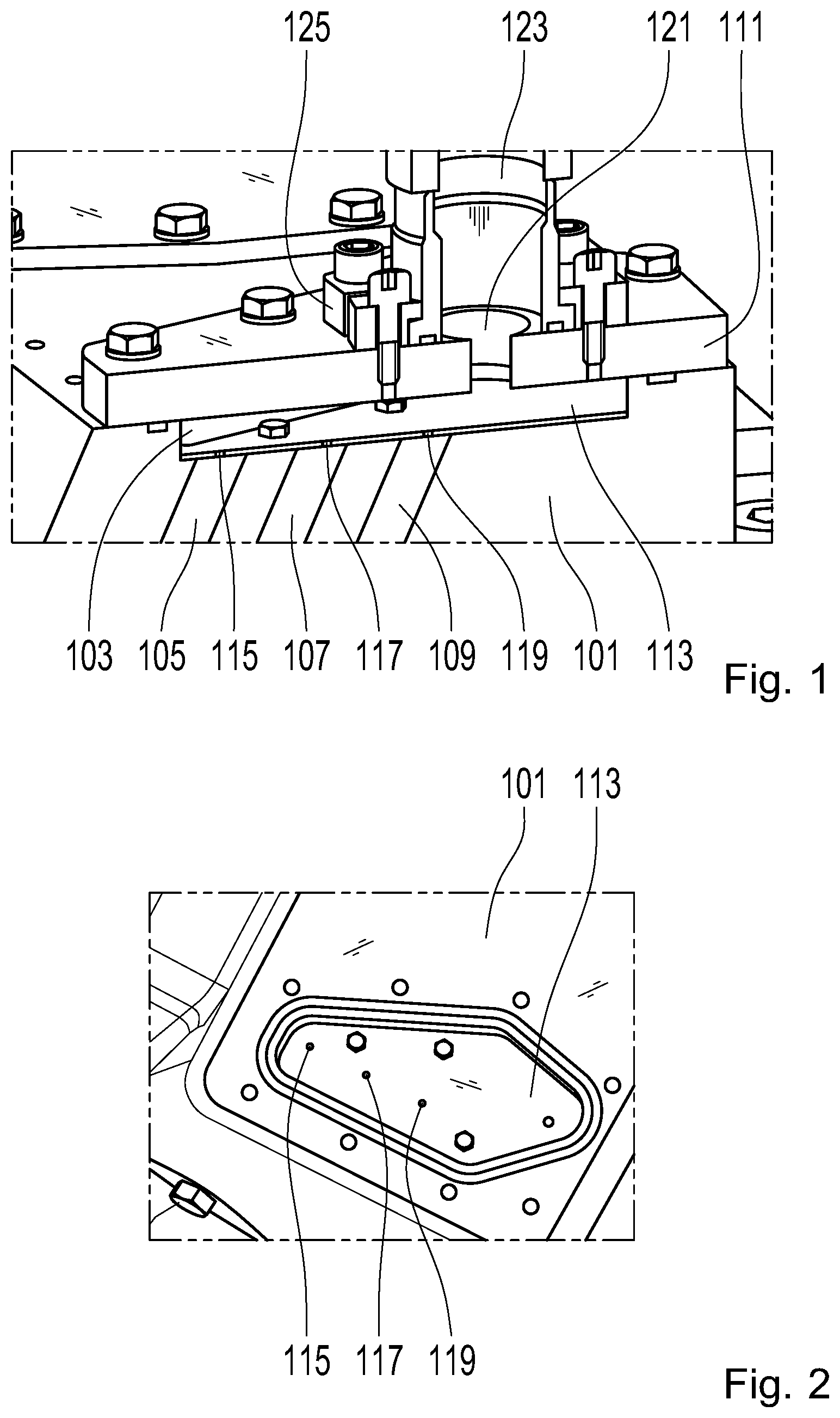
[0007] FIG. 1 shows a cross-section of an oil distributor; and
[0008] FIG. 2 shows the oil distributor in the open state.
DETAILED DESCRIPTION
[0009] Embodiments of the invention eliminate disadvantages inherent in solutions known from the prior art. In particular, embodiments of the invention reduce the risk of error during the assembly of oil lines and the costs.
[0010] According to the invention, an arrangement is provided that includes a first oil line, a second oil line, a third oil line and a cavity. An oil line can be understood as a device for conducting oil. Usually, an oil line is designed as a pipe or bore. A cavity can refer to a volume enclosed by one or more walls.
[0011] In the arrangement, the first oil line, the second oil line and the third oil line each open into the cavity, i.e. the first oil line, the second oil line and the third oil line each open into the cavity, i.e. each have a mouth in the cavity. As a result, the first oil line, the second oil line and the third oil line are all connected to the cavity in an oil-conducting manner.
[0012] A plate having a first hole and a second hole is provided according to the invention. The first hole and the second hole are continuous, i.e. they extend from one side of the plate to the opposite side. Both sides of the plate are thus each connected to conduct oil through the first hole and the second hole. The holes are, for instance, bores.
[0013] The mouths of the second oil line and the third oil line are covered by the plate. This implies that the plate is in the cavity.
[0014] In order to obtain the fluid-conducting connection between the mouth of the second oil line and the cavity and between the mouth of the third oil line and the cavity, the first hole and the second hole are arranged above the mouths. The first hole is located above the mouth of the second oil line. Accordingly, the third hole is located above the mouth of the third oil line. The first hole thus connects the second oil line and the cavity to each other in an oil-conducting manner Accordingly, the second hole connects the third oil line and the cavity to each other in an oil-conducting manner
[0015] The holes assume the function of the diaphragms mentioned at the outset. The use of a single plate instead of a plurality of diaphragms simplifies assembly. The risk of assembly errors is also reduced.
[0016] The arrangement is preferably developed with a component and a cover. The component has a recess. It is preferably designed as one piece. An edge of the recess preferably runs in one plane.
[0017] The cover covers the recess so as to form the above-described cavity. In particular, the cover covers the recess in an oil-tight manner Thus, no oil can escape from the cavity between the edge of the recess and the cover.
[0018] The second oil line and the third oil line open into the recess. The mouths of the second oil line and of the third oil line are therefore located in the recess, preferably at the bottom of the recess.
[0019] In a preferred development, the recess has at least one flat face. The face is preferably a base face of the recess, i.e. a face which forms the bottom of the recess. At its edges, the face merges into the side faces of the recess. The side faces in turn connect the edge of the recess to the base. The edge is formed by edges of the side faces.
[0020] According to a development, the second oil line and the third oil line open into the face. This means that the mouths of the oil line lie in the face and are each surrounded by the face. Furthermore, the plate is fixed to the face. For this purpose, the shape of the plate must correspond to the shape of the face. In particular, a flat plate is preferred.
[0021] In a further preferred development, the first oil line passes through the cover. This implies that the cover has a through-hole that connects the first oil line and the cavity to one another in an oil-conducting manner As described above, the hole forms part of the first oil line.
[0022] In order to further lower the risk of assembly errors, the plate and the face are congruent in a preferred development. In particular, the plate can have a base face, a top face and at least one side face which connects the base face and the top face to one another. According to the development, the base face rests on the face of the recess. Its edges and the edges of the face of the recess run adjacent to each other. In particular, each edge at each point contacts a point of the other edge. Mouths of the first hole and the second hole are respectively located in the base face and in the top face of the plate. The base face and the top face are preferably congruent. This means that the two faces can be converted into one another by congruence mapping.
[0023] According to the development, the face of the recess and thus also the plate or its base face are not rotationally symmetrical. In this way, it can be ensured that the plate can be fixed in exactly one position on the face. Assembly errors are thereby impossible. In particular, the correct arrangement of the first hole and the second hole on the respective mouth of the second oil line and the third oil line can thus be ensured.
[0024] The arrangement is moreover preferably further developed with an oil circuit. The first oil line, the second oil line, the third oil line and the cavity are integrated into the oil circuit such that oil is introduced into the cavity from the first oil line. Since the cavity is connected in a fluid-conducting manner to the second oil line via the first hole and to the third oil line via the second hole, the oil consequently passes from the cavity into the second oil line and the third oil line. Thus, the oil is discharged from the cavity through the second oil line and the third oil line. The distribution of the oil to the second oil line and the third oil line is proportionate in accordance with the size of the first hole and the second hole.
[0025] The arrangement is particularly suitable for use in a gearbox, for example in a gearbox for a wind turbine. A housing of the gearbox forms the component described above. This implies that the housing has a recess that is covered by the cover. The second oil line and the third oil line are introduced into the housing, for instance in the form of bores. The first oil line is preferably designed as a tube and flanged onto the cover.
[0026] FIG. 1 shows a gearbox housing 101 in the wall of which a recess 103 is introduced. The wall of the gearbox housing 101 has a first bore 105, a second bore 107 and a third bore 109, each opening into the recess 103. A first plate 111 is screwed to the wall of the gearbox housing 101 and covers the recess 103. Thus, the first plate 111 and the recess 103 form a cavity.
[0027] A second plate 113 is arranged within the cavity formed by the recess 103 and the plate 111. This is screwed to the wall of the gearbox housing 101 at the bottom of the recess and covers the first bore 105, the second bore 107 and the third bore 109. The second plate 113 has a first hole 115, a second hole 117 and a third hole 119. The holes 115, 117, 119 are each designed continuous.
[0028] The first hole 115 connects the cavity and the first bore 105 to each other in a fluid-conducting manner; the second hole 117 connects the cavity and the second bore 107 to each other in a fluid-conducting manner; and the third hole 119 connects the cavity and the third bore 109 to each other in a fluid-conducting manner
[0029] The first plate 111 has a fourth hole 121. This is also designed continuous.
[0030] To introduce oil into the cavity, a tube 123 is provided. The tube 123 is fixed to the first plate 111 such that a mouth of the tube 123 covers the fourth hole 121. Thus, the tube opens into the fourth hole 121.
[0031] A ring 125 fixes the tube 123 in a keyed fit. The ring 125 in turn is screwed to the first plate 111. In order to be able to better install the ring 125, it is of two-piece design.
[0032] FIG. 2 shows the gearbox housing 101 without the first plate 111 and the tube 123. The second plate 113 can be seen at the bottom of the recess 103. A groove extends along an edge of the recess 103 into which a seal can be inserted. The plate 113 is encircled by the side faces of the recess 103. In this way, the position of the second plate 113 within the recess 103 is clearly established.
[0033] While the invention has been illustrated and described in detail in the drawings and foregoing description, such illustration and description are to be considered illustrative or exemplary and not restrictive. It will be understood that changes and modifications may be made by those of ordinary skill within the scope of the following claims. In particular, the present invention covers further embodiments with any combination of features from different embodiments described above and below.
[0034] The terms used in the claims should be construed to have the broadest reasonable interpretation consistent with the foregoing description. For example, the use of the article "a" or "the" in introducing an element should not be interpreted as being exclusive of a plurality of elements. Likewise, the recitation of "or" should be interpreted as being inclusive, such that the recitation of "A or B" is not exclusive of "A and B," unless it is clear from the context or the foregoing description that only one of A and B is intended. Further, the recitation of "at least one of A, B and C" should be interpreted as one or more of a group of elements consisting of A, B and C, and should not be interpreted as requiring at least one of each of the listed elements A, B and C, regardless of whether A, B and C are related as categories or otherwise. Moreover, the recitation of "A, B and/or C" or "at least one of A, B or C" should be interpreted as including any singular entity from the listed elements, e.g., A, any subset from the listed elements, e.g., A and B, or the entire list of elements A, B and C.
LIST OF REFERENCE NUMERALS
[0035] 101 Gearbox housing
[0036] 103 Recess
[0037] 105 First bore
[0038] 107 Second bore
[0039] 109 Third bore
[0040] 111 First plate
[0041] 113 Second plate
[0042] 115 First hole
[0043] 117 Second hole
[0044] 119 Third hole
[0045] 121 Fourth hole
[0046] 123 Tube
[0047] 125 Ring
* * * * *
D00000
D00001
XML
uspto.report is an independent third-party trademark research tool that is not affiliated, endorsed, or sponsored by the United States Patent and Trademark Office (USPTO) or any other governmental organization. The information provided by uspto.report is based on publicly available data at the time of writing and is intended for informational purposes only.
While we strive to provide accurate and up-to-date information, we do not guarantee the accuracy, completeness, reliability, or suitability of the information displayed on this site. The use of this site is at your own risk. Any reliance you place on such information is therefore strictly at your own risk.
All official trademark data, including owner information, should be verified by visiting the official USPTO website at www.uspto.gov. This site is not intended to replace professional legal advice and should not be used as a substitute for consulting with a legal professional who is knowledgeable about trademark law.