Portable Canopy With Drainage System
Aloumanis; Peter ; et al.
U.S. patent application number 16/285166 was filed with the patent office on 2020-08-27 for portable canopy with drainage system. The applicant listed for this patent is Peter Aloumanis, Claudio Santiago Ribeiro. Invention is credited to Peter Aloumanis, Claudio Santiago Ribeiro.
| Application Number | 20200270893 16/285166 |
| Document ID | / |
| Family ID | 1000004245193 |
| Filed Date | 2020-08-27 |


| United States Patent Application | 20200270893 |
| Kind Code | A1 |
| Aloumanis; Peter ; et al. | August 27, 2020 |
PORTABLE CANOPY WITH DRAINAGE SYSTEM
Abstract
A portable canopy having a portable frame, a portable cover, a drainage system and an installed and transport state. The portable cover is made from a flexible, water-resistant fabric. The drainage system comprising conduits for transporting liquids. In the installed state a first volume under roof shelters objects. The portable frame provides a support structure for the first volume. In the installed state the portable frame structurally supports the portable cover. In the installed state the conduits transport rain striking the roof to an outlet positioned at one of the vertical support members. The transport state has a second volume at least five times less than the first volume. The portable canopy is a temporary shelter configured to be repetitively altered between the installation state the transport state.
| Inventors: | Aloumanis; Peter; (Boca Raton, FL) ; Ribeiro; Claudio Santiago; (Evanston, IL) | ||||||||||
| Applicant: |
|
||||||||||
|---|---|---|---|---|---|---|---|---|---|---|---|
| Family ID: | 1000004245193 | ||||||||||
| Appl. No.: | 16/285166 | ||||||||||
| Filed: | February 25, 2019 |
| Current U.S. Class: | 1/1 |
| Current CPC Class: | E04H 15/44 20130101; E04H 15/60 20130101; E04H 15/02 20130101; E03B 3/02 20130101; E04H 15/54 20130101 |
| International Class: | E04H 15/02 20060101 E04H015/02; E04H 15/44 20060101 E04H015/44; E04H 15/54 20060101 E04H015/54; E04H 15/60 20060101 E04H015/60; E03B 3/02 20060101 E03B003/02 |
Claims
1. A portable canopy comprising: a portable frame comprising vertical support members and horizontal liquid flow members; a portable cover made from a flexible, water-resistant fabric; a drainage system comprising conduits for transporting liquids; an installed state for the portable frame, the portable cover and the drainage system having a width, a length, and a height, which together establish a first volume, wherein the first volume is a volume under roof that shelters objects within the first volume, wherein the portable frame provides a support structure for the first volume, wherein in the installed state the portable frame structurally supports the portable cover, wherein in the installed state the conduits transport rain striking the roof to an outlet positioned at one of the vertical support members; and a transport state for the portable frame, the portable cover and the drainage system having a second volume at least five times less than the first volume, wherein the portable canopy is a temporary shelter configured to be repetitively altered between the installation state the transport state, whereby the portable canopy in the installation state shelters the objects in the first volume for events during which the portable canopy is utilized, whereby the portable canopy in the transport state facilitates transport of the portable canopy between locations and diminishes a storage footprint of the portable canopy while not in use for the events.
2. The portable canopy of claim 1, wherein the width is at least four feet, the length is at least four feet, and the height is at least six feet.
3. The portable canopy of claim 1, wherein a longest linear dimension of the second volume is at most five feet.
4. The portable canopy of claim 1, wherein at least a portion of the conduits are an interior volume of at least a portion of the vertical support structures.
5. The portable canopy of claim 1, wherein at least a portion of the conduits are an interior volume of at least a portion of the horizontal liquid flow members are horizontal support structures.
6. The portable canopy of claim 1, wherein each of the vertical support structures is hollow, wherein the liquids are conveyed through the vertical support structures.
7. The portable canopy of claim 1, wherein each of the horizontal liquid flow members are horizontal support structures, which are hollow, wherein the liquids are conveyed through the horizontal support structures.
8. The portal canopy of claim 1, wherein the outlet is designed to be attachable to an end of a hose for directing the liquids away from the portable canopy.
9. The portable canopy of claim 1, wherein the outlet is a quick connect fitting configured to be paired to a quick connect adaptor of a garden hose, the garden hose when connected to the outlet via the quick connect fitting and quick connect adaptor is configured to direct the liquids away from the portable canopy.
10. The portable canopy of claim 1, wherein in the installation state the roof comprises an exposed drain connected to the conduits, wherein the roof and the conduits are configured so that gravity directs the liquids from the roof through the conduits to the outlet.
11. The portable canopy of claim 1, wherein at least a portion of the vertical support structures are hollow, wherein in the installation state at least a portion of the liquid is configured to be retained within the vertical support structures as a ballast adding stability and weight to the portable canopy.
12. The portable canopy of claim 1, wherein in the installation state each of the the horizontal liquid flow members are horizontal support structures, which are downwardly sloping to permit conduits adjacent to or contained within the horizontal support structures to direct the liquids to the outlet using a force of gravity.
13. The portable canopy of claim 1, wherein in the installation state at least two sides of the portable canopy are covered by the portable cover.
14. The portable canopy of claim 1, wherein in the installation state at least one side, referred to as an open-able side, of the portable canopy has an open state and a closed state, wherein in the open state the open-able side is not covered by a portion of the canopy, wherein in the closed state the open-able side is covered by the portion of the canopy, wherein material of the portion of the canopy of the open-able side is rolled up in a stable position near a portion of the roof when in the open state.
15. The portable canopy of claim 14, wherein one of the conduits, referred to as a side conduit, linearly extends through the open-able side such that the side conduit does not direct the liquids to the outlet when the open-able side is in the open state, wherein the side conduit attaches to other ones of the conduits when the open-able side is in the closed state such that the side conduit directs the liquids to the outlet when the open-able side is in the closed state.
16. The portable canopy of claim 1, wherein at least a portion of the portable cover is hollow and configured to contain pressurized air, wherein the portable cover comprises an air plug, wherein in the installation state the portable cover is configured to be inflated via an air pump to contain the pressurized air, wherein inflation of the portable cover to contain the pressurized air helps direct a flow of the liquids.
17. The portable canopy of claim 1, wherein substantially all rain striking the roof is directed to the outlet.
18. The portable canopy of claim 1, further comprising: a water pump configured to direct a flow of the liquid through the conduits and out the outlet.
19. A portable canopy comprising: a portable frame comprising vertical support members and the horizontal liquid flow members; a portable cover made from a flexible, water-resistant fabric; a drainage system comprising conduits for transporting liquids; an installed state having a width, a length, and a height, which together establish a first volume, wherein the width is at least four feet, the length is at least four feet, and the height is at least six feet, wherein the first volume is a volume under roof that shelters objects within the first volume, wherein in the installed state the conduits transport rain striking the roof to an outlet positioned at one of the vertical support members; and a transport state for the portable frame, the portable cover and the drainage system having a second volume at least five times less than the first volume, wherein a longest linear dimension of the second volume is at most five feet.
20. A portable canopy comprising: a portable frame comprising vertical support members and the horizontal liquid flow members; a portable cover made from a flexible, water-resistant fabric; and a drainage system comprising conduits for transporting liquids, wherein each of the vertical support members is a leg supporting a roof covered by the portable cover, wherein each of the vertical support structures is hollow, wherein the liquids are conveyed through the vertical support structures, wherein the portable canopy has an installed state and a transport state, wherein in the installed state a first volume under roof shelters objects, wherein the portable frame provides a support structure for the first volume, wherein in the installed state the portable frame structurally supports the portable cover, wherein in the installed state the conduits transport rain striking the roof to an outlet positioned at one of the vertical support members, wherein the transport state has a second volume at least five times less than the first volume, wherein the portable canopy is a temporary shelter configured to be repetitively altered between the installation state the transport state.
Description
CROSS-REFERENCE TO RELATED APPLICATIONS
[0001] This continuation-in-part application claims the benefit of U.S. patent application Ser. No. 15/431,886 filed 14 Feb. 2017 entitled "A Self-Draining Umbrella" and U.S. patent application Ser. No. 15/007,464 filed 27 Jan. 2016 now U.S. Pat. No. 9,714,521 entitled "A Self-Draining Canopy" The entire contents of U.S. application Ser. No. 15/431,886 and 15/007,464 are incorporated by reference herein
BACKGROUND
[0002] The present invention relates to the field of shelters and, more particularly, to a portable canopy with a drainage system.
[0003] Portable shelters like the "pop-up" or portable canopy are owned and used by many people to provide protection from sun and rain during outdoor activities, such as parties and bar-be-ques. The portability of the portable canopy (also referred to as a party tent) is provided by a light-weight and collapsible support structure (e.g., frame) with an attached covering. The covering is a flexible material, which collapses for transport and storage. The flexible material is often a water proof polyester fabric, which blocks a high percentage of ultra-violet (UV) rays from the sun. The support structure or frame is often formed from rust resistant steel poles able to telescope (with push-pins), which collapse into a small footprint for transport. A bag or container often is designed to store the folded covering and frame elements in a relatively light-weight package, which may or may not be wheeled for ease of human transport on location. Further, transport of the canopy shelters generally limits the overall dimensions, as standard vehicles (such as passenger cars and vehicles) are typically used to convey the portable canopies to and from a desired event location. In short, canopy shelters must generally strike a balance of footprint, weight, durability, transportability, ease of setup/tear down, and cost. Consequently, the design considerations of canopy shelters are significantly different from those of substantially permanent structures. Permanent structures refer to those designed to remain in place for significant periods of time, as opposed to being utilized for a specific party or other short-term event.
[0004] Many portable canopies are configured to produce a quadrilateral (e.g., square or rectangular) frame. This results in the covering being formed into the shape of a square or rectangular pyramid (i.e., a square or rectangular base with triangular sides having a common vertex). The sides or walls of portable canopies may be exposed or covered, depending on design. Other designs, such as hexagonal portable canopies, exist, but are less common.
[0005] By design, portable canopies provide a relatively safe space for humans to gather during adverse weather conditions, such as rain. Thus, rain and adverse weather is one of the key considerations (another being UV protection) for the use of the portable canopies. Conventional canopies often permit water to pool on the canopy top. Eliminating the water pool generally requires a person positioned under the depressed area within which water pools to push against the depressed area. This manual manipulation of the flexible covering causes water to flow downwards off the side(s) of the canopy roof. Over time, exposure to a weight of intermittent water pools and manual water clearing actions deforms the contour of the covering, reducing the overall life of the canopy.
BRIEF DESCRIPTION OF THE SEVERAL VIEWS OF THE DRAWINGS
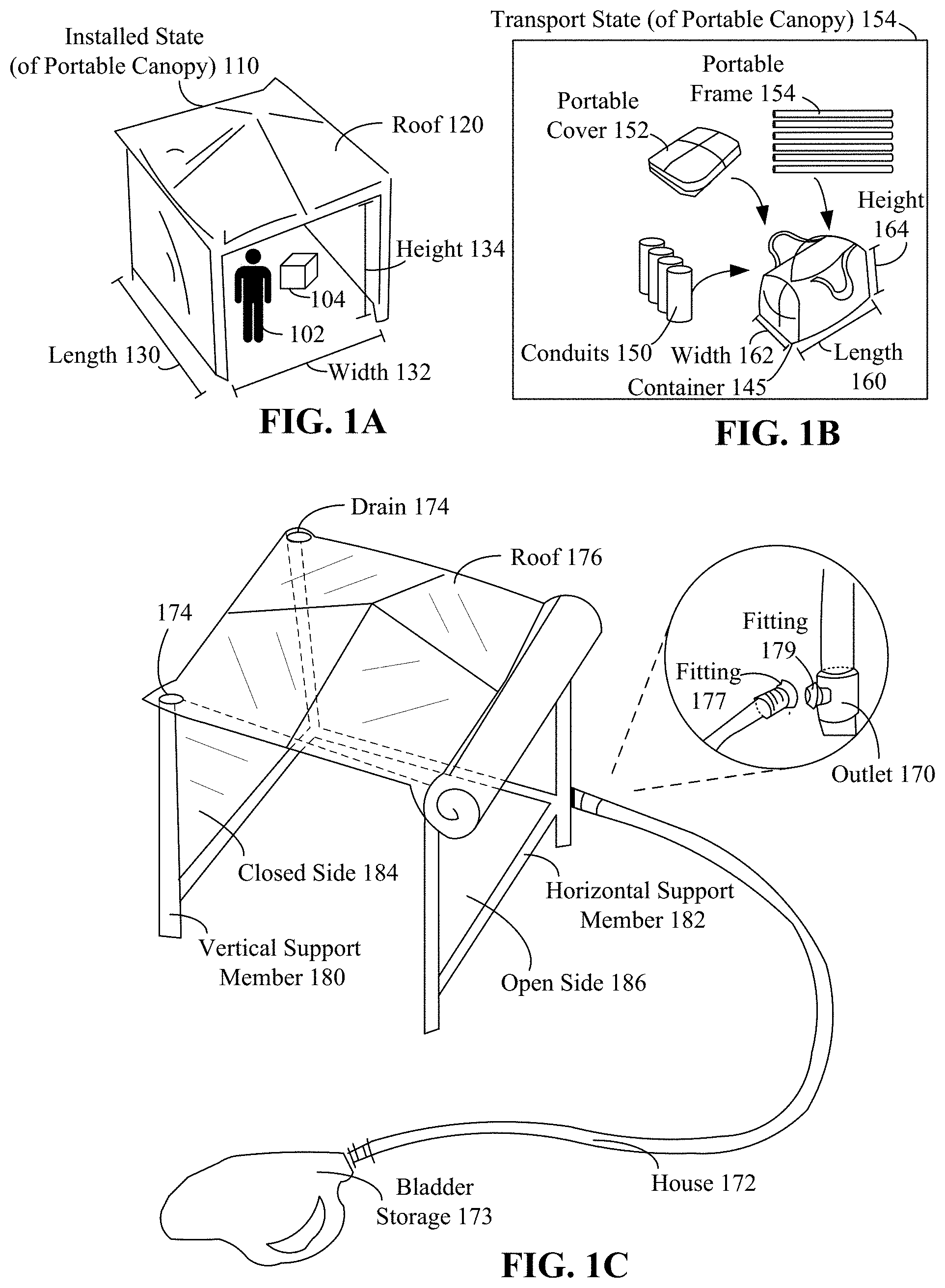
[0006] FIGS. 1A and 1B show a portable canopy in an installed state and a transport state in accordance with an embodiment of the disclosure.
[0007] FIG. 1C shows an embodiment of a portable canopy with an open-able side, which is shown in an open state.
[0008] FIG. 2 is a block diagram presenting the components of a portable canopy in accordance with embodiments of the disclosure.
[0009] FIG. 3 depicts isometric views of the portable canopy in accordance with embodiments of the inventive arrangements disclosed herein.
[0010] FIG. 4A presents enlarged illustrations of the drainage system of the self-draining canopy in accordance with embodiments of the inventive arrangements disclosed herein.
[0011] FIG. 4B shows an implementation of the drainage system.
[0012] FIGS. 5A and 5B show an arrangement for a portable canopy roof and a single drain in one embodiment.
[0013] FIGS. 6A and 6B show an open-able side configuration with internal conduits in accordance with an embodiment of the disclosure.
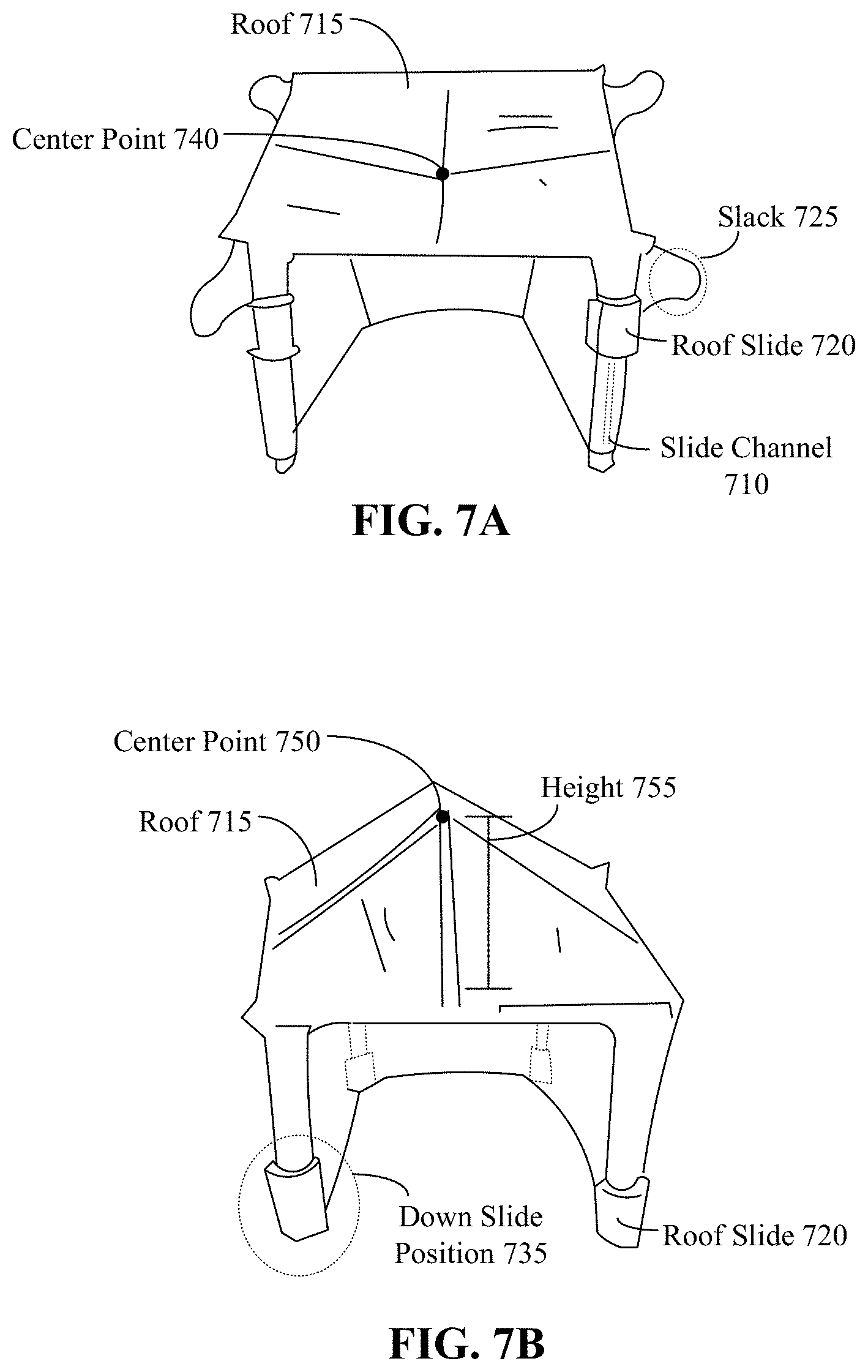
[0014] FIGS. 7A and 7B show the portable canopy with a downward roof-slid action in accordance with an embodiment of the disclosure.
[0015] FIGS. 8A and B shows an air inflatable embodiment where at least a portion of the flexible fabric of the portable canvas can include an air chamber.
[0016] FIGS. 8C and 8D shows conduits and contours of the portable canopy, which permit liquid to flow via gravity from the roof to an outlet can be shaped/formed at least in part due to an air pressure.
DETAILED DESCRIPTION
[0017] The disclosure includes a portable canopy with included conduits for water redirection. The portable canopy, or portable shelter, is designed to be set-up and torn down rapidly for events, such as parties. Humans and objects shelter under the portable canopy for protection from rain and other environmental conditions, such as ultra-violet (UV) radiation. Unlike fixed structures, such as car ports or sheds, the portable canopy must be light-weight and able to be transported/stored easily. A portable canopy is formed using a portable frame having vertical and horizontal support members, which provide structural support. A cover, such as a flexible, water-resistant fabric, extends over the frame. The drainage system includes a set of conduits, such as pipes, for directing and transporting fluids. When installed (i.e., in an installed state), a volume under roof is created sufficient to shelter a number of humans.
[0018] The drainage system of the portable canopy directs rain (or other liquids) falling on the roof of the canopy to an outlet. The roof is contoured to minimize an accumulation or polling of water during a storm or other adverse weather condition, for which the portable canopy. The roof and water direction elements are further designed so that water does not fall off the sides of the canopy in chaotic ways; with the unfortunate, undesired, and conventionally common side effect of drenching humans being sheltered by the portably canopy as they enter and leave the shelter. Unlike conventional portable canopies (which have a solid roof formed by stretching the canopy over the frame and what lack water-redirection conduits), a top of the disclosed portable canopy can include a set of one or more drains. In one embodiment, each corner (assuming a rectangular portable shelter, which is common) includes a drain, which downwardly directs water to a conduit, which is integrated with vertical support members (i.e., support legs of the canopy). Embodiments exist where the conduits are adjacent to or otherwise tied to the legs, as opposed to being part of hollow legs, within which roof-striking water is directed. Horizontal conduits may direct water from the various corners to a centralized location or outlet. The horizontal conduits are integrated within horizontal support members (side supports of the frame) in embodiments and are adjacent to these horizontal support members in others. The horizontal conduits as referred herein mean the conduits (whether physically horizontal or not, which causes a flow of liquid across horizontal stretches of the canopy. In one embodiment, the horizontal conduits are a set of hoses or conduits between poles A and B. For example, at least a portion of the "horizontal conduits" are able to be integrated within the fabric of the canopy cover in embodiments. The outlet can include a fitting compatible with a hose (e.g.,. garden hose) fitting to allow water to be directed by the hose. A water storage bladder may be used on the other end of the hose in situations where no convenient run-off location is proximate to the portable canopy. All of the components of the portable shelter, including the conduits, must be light-weight, easily decomposable, and easily set-up/torn down due to the nature of use of the portable shelter. Bulky or heavy additions are not feasible for use of a portable canopy, which must be easily transportable in a transportation state.
[0019] Portable canopies of the disclosure in an installed state provide at least a four foot by four foot by six foot space, which is often ten by ten feet, twelve by ten feet, or twenty by twenty feet, depending on the space desired for an event for which the portable canopy is used. Humans can typically stand under a portable canopy, which is why the height is generally at least six feet. In a transport state, the portable canopy consumes considerably less space, such as having a volume of 5 times less than that of the interior volume of the installed state canopy. Carrying bags with handles or wheels are often used to contain the elements (support poles, folded flexible canvas, conduits, etc.) of the portable canopy in the transport state. Support structures, often made of metal or other high-strength, low footprint materials are collapsed or otherwise deconstructed in the transport state. Vertical support members used as legs of the portable canopy are often telescoping or easily constructed from smaller linear segments joined through a push-pin type of coupler. The flexible canvas is folded upon itself to minimize space/volume consumption in the transport state, as well. Some components of some portable shelter are coupled directly to supports, which are often hinged for easy expansion and set-up/tear down, so that structures, such as a roof, can be easily expanded/contracted. Other portable shelters use ties, hook-and-loop fasteners, or other couplers to join the flexible fabric, which is removable, to a frame. In the installed state, a sufficient structural integrity to withstand environmental forces, inadvertent human contact, and storms is needed.
[0020] A first consideration for the transport state being reasonably portable includes the ease to move the portable shelter from location to location, such as within a standard vehicle. For this reason, the largest linear dimension of a portable structure is often five feet or less, as longer members have difficulty being transported in passenger vehicles. Diminishing the footprint and volume of the transport state canopy to fit in a trunk of a passenger vehicle is often preferred, but come larger portable canopies are often designed for transport by truck or commercial transport, which lessons the restrictions on the largest linear dimension in embodiments. Other embodiments are contemplated for more `permanent" canopies, which have less stringent requirements for transport and storage especially with regard to the largest linear dimension. For example, many "party canopies" from professional service companies are less compact and have larger linear dimensions, such as the tent poles vertically supporting the canopy being a single solid metal leg of approximately seven to eight feet in length. A second consideration for the transport state is an ability to move the portable canopy on-site from a loading/unloading point to a position, where the canopy is to be set-up, which is typically an outdoor position. An overall weight and bulk are significant for this second consideration, especially when a bag is used to hold the entire portable shelter when in the transport state. Some larger commercial/rental portable canopies are heavy enough so that on-site transportation is performed, or intended to be performed, by multiple people lifting various components as a team.
[0021] FIGS. 1A and 1B show a portable canopy in an installed state 110 and a transport state 140 in accordance with an embodiment of the disclosure. The portable canopy is a temporary shelter configured to be repetitively altered between the installation state 110 the transport state 140. The portable canopy in the installation state 110 shelters objects 102, 104 in a volume defined by a length 130, a width 132, and a height 134. The volume is the interior space of the portable canopy, which is a region under roof 120. As shown, the portable canopy is a rectangular structure with four sides. Embodiments exist with other numbers of sides (such as six or eight for hexagonal and octagonal structures) and even ones where the perimeter is circular or oval in shape. Various ones of the sides of the portable canopy can be covered or open. Structural support for the portable shelter is provided by a portable frame 154. A portable cover 152 is supported by and extends over the portable frame. The portable canopy includes conduits 150, which transport rain striking the roof to an outlet, which is positioned at the perimeter near one of the supporting legs, which is also a vertical support member of the portable frame 154. The portable canopy in the transport state 140 facilitates transport of the portable canopy between locations and diminishes a storage footprint of the portable canopy while not in use for the events. The transport state 140 may include a container 145 within which the conduits 150, portable cover 152, and portable frame 154 fits. The container 145 has a length 160 width 162, and height 164 that together create a transport volume. The transport volume is at most one fifth of the volume formed by length 130, width 132, and height 134.
[0022] FIG. 1C shows an embodiment of a portable canopy with an open-able side, which is shown in an open state 188. The open-able side has a closed and an open state. In the open state 188, the cover is removed from the frame on that side. For example, a portion of the cover can be rolled upwards and be topmost affixed, such as being attached to the roof 176. In the closed state, the canvas covers the respective wall, as shown by closed side 184. Legs of the portable canopy are vertical support members 180, which may be hollow to concurrently function as conduits for transporting liquid from roof 176 to outlet 170. Structural stability in the frame may be enhanced with one or more horizontal support members 182. These members 182 are also hollow in embodiments, so that they are able to transport liquid towards the outlet 170. Although referred to as horizontal members, each shown horizontal support member 182 downwardly slopes and has a lowest point above the position of the outlet 170. This ensures that gravity will cause interior liquids to flow towards the outlet for release. Drain(s) 174 can exist in the top of the roof 176, which is contoured to ensure that water is directed to openings of the drain(s) 174. In one embodiment, the horizontal support member 182 is substituted with a horizontal liquid flow member. These horizontal liquid flow members direct a flow of liquid between poles (or horizontal stretches of the portable canopy). Embodiments are contemplated where horizontal liquid flow members provide a minimal amount of structural support, in which case additional support elements are able to be utilized in conjunction with the flow members to ensure structural stability.
[0023] Conduits (e.g., hollow vertical and horizontal support members 180 and 182) use gravity to direct liquid (i.e., rain water striking the roof) towards outlet 170. The outlet 170 includes a fitting configured to be paired to compatible fitting of a house 172. In one embodiment, the fitting is a quick connect adaptor. The house 172 can be directed to a run off location to or a bladder (or other liquid) storage 173.
[0024] FIG. 2 is a block diagram presenting the components of a portable canopy in accordance with embodiments of the disclosure. The portable cover 205 of the canopy can be of a size, shape, and materials that is similar to the variety of existing canopies and compatible with the size, shape, and bearing capacity of the supporting portable frame 210. It can be preferred that the portable cover 205 be of a water-resistant material as rain or water accumulation is of concern. The material for portable cover 205 is often preferably resistant to ultra-violet (UV) radiation.
[0025] The portable cover 205 can be coupled to the portions of the portable frame 210 using conventional means. The portable frame 210 of the portable canopy can support the cover 205 in embodiments. Support members may be largely at right angles form a rectangular frame for a rectangular shaped portable canopy. Portions of the portable frame 210 can be collapsible with an attached covering. The collapsible structure can be designed for easy expansion/contraction and may lock in place, such as with push-pins. When the portable frame 210 (in an installation state) is locked into place, edges of the cover 205 are stretched along the sides of the support structure and the center of the covering is lifted upwards to create the canopy shape, in embodiments. Many collapsible support structures, which are contemplated embodiments for portable frame 210, are configured to produce a quadrilateral (e.g., square or rectangular) frame.
[0026] The portable frame 210 can include multiple legs 215, a perimeter frame 220, and roof support 225. In one embodiment, the legs 215 are vertical support members of the perimeter frame 220 itself. The legs 215 can be the vertical supports of the canopy 200 with the perimeter frame 220 laterally connecting the legs 215 to provide stability. Horizontal support between legs 215 can be provided from spacing elements that are part of the roof support 225 and/or based on other elements of the perimeter frame 220. In embodiments, lower (positioned close to the ground, or at least lower than the vertical midway point) supports may or may not exist for stability. For simplicity in discussion, the portable canopy can have four legs 215 whose positions are the corners of a square in the horizontal plane. It should be noted that the portable canopy utilize different quantities of legs 215 that are positioned to define other geometrical shapes in the horizontal plane without deviating from the spirit of the present invention. That is, the disclosure is not limited to a rectangular arrangement, and hexagonal, octagonal, and rectangular arrangements are also contemplated, which are each derivatives of the base discussion, which are easily understood and able to be formed by one of ordinary skill in light of the disclosure provided herein.
[0027] The roof support 225 can be the component of the portable canopy that direct supports (i.e., comes into contact with) a roof portion of the cover 205. The canopy support 225 of the portable canopy can include vertical support member(s) 230, angled support member(s) 235, and planar support member(s) 240. While similar components are used in the support structures of conventional canopies, the orientation of the non-vertical components 235 and 240 can be unique to the portable canopy 200. The non-vertical components 235 and 240 create "structure" that cause a natural contouring of the top surface of the roof to allow gravity to ensure water flows towards drain openings.
[0028] As in conventional canopies, a vertical support member 230 can lift a center point of the cover 205 a predetermined height above the height established by the legs 215. The planar support members 240 can connect the bottom of the vertical support member 230 to the perimeter frame 220. Unlike similar components of conventional canopies, the planar support members 240 of the self-draining canopy can be orthogonally connected (at a 90 degree angle) to the perimeter frame 220 with respect to the horizontal plane.
[0029] The angled support members 235 can be elements that comprise the hypotenuses of the right triangles that they form with the vertical support member 230 and planar support members 240. That is, the angled support members 235 can connect the top of the vertical support member 230 to the perimeter frame 220 at a point where the planar support members 240 connect to the perimeter frame 220. The covering 205 can directly rest upon the angled support members 235.
[0030] The angles of the canopy support 225 can allow the covering 205 to naturally direct rain/water down towards the corners. Conventional canopies with diagonal support of the covering 205 have support components or a natural contour that directs rain/water away from the corners towards the middle of the lateral face where the rain/water accumulates. The disclosure's roof directs rain/water towards the corners, by elevating a center point of the roof and permitting the flexible fabric of the cover to naturally contour to direct roof-striking rain to a set of one or more drains. Other embodiments exist for the roof structure, such that the roof is slanted to direct rain towards a drain, such as conduits are formed within the roof for water direction, and the like; all of which are within scope of the disclosure.
[0031] The components of the portable frame 210 can be connected to each other using suitable means and can utilize approaches and/or techniques taught by conventional canopies. Near the corners of the roof, where the rain/water is directed, the portable canopy can have drains 250, which are part of drainage system 245. The drainage system 245 can include drains 250, conduits 255, and at least one outlet 257. The drain 250 can be an element that introduces one or more apertures in the cover 205 that allow rain/water to pass through to a connected conduit 255.
[0032] The conduit 255 can be the means that allows the rain/water to flow from the drain 250 to a designated outlet location, such as outlet 257. For example, the conduit 255 can be a piece of tubing connected to the drain 250 with the outlet location being the opposite end of the tubing. As another example, the conduit 255 can be integrated into the legs 215. That is, the legs 215 can have a hollow, interior channel that is connected to the drains 250.
[0033] It should be noted that the drainage system 245 can handle substances other than rain/water, including, but not limited to, sand, soil particulates, snow, ice particulates, sleet, dust, ash, liquid solutions, other non-hazardous or non-detrimental liquids, and combinations thereof.
[0034] FIG. 3 depicts an isometric views of the portable canopy in accordance with embodiments of the inventive arrangements disclosed herein. Portable canopy has a roof support structure with a square base. Four legs 325, one per corner, are vertical support members of the perimeter frame 322. The vertical support member 315 of the roof structure lifts a center point of the covering 310. Unlike conventional canopies, angled support members 320 can be connected to the midpoints of each side of the perimeter frame 322 and the top of the vertical support member 315. In a conventional canopy, the angled support members 320 can be omitted or connected to the top of the legs 325 to form a regular square pyramid. The connection of the angled support members 320 to the perimeter frame 322 can be aligned with the planar support members 335, as shown. The canopy support includes the vertical support member 315, angled support members 320, and planar support members 335. Essentially, the vertical support member 315, angled support members 320, and planar support members 335 can represent two king post trusses that orthogonally intersect at the vertical support member 315.
[0035] Since the position of the angled support members 320 are orthogonal and not diagonal, the expected pyramidal shape of the covering 310 can be thought of having been rotated 90.degree. in the horizontal plane. That is, the edges of the pyramid, represented by the angled support members 320, do not align with the corners of the square base as in a square pyramid. Additionally, the lateral sides of the expected pyramidal shape cannot be completely flat due to the legs 325 pulling the midpoint of the base edge of the lateral side to the corner of the square base. As a result, the covering 310 has a natural contour 312 on the diagonal that slopes downward towards the legs 325. The force of gravity can direct rain/water that falls on the covering 310 along the natural contour 312 towards the legs 325.
[0036] The purpose for having this diagonally-directed the natural contour permits rain/water to be naturally directed towards the corners of the square base. The drainage system 340 is positioned at the corners to remove the rain/water from the covering 310. Therefore, rain/water cannot accumulate on top of the covering 310 and deformation to the covering 310 by the weight of accumulated water can be prevented, which can extend the overall life of the portable canopy.
[0037] FIG. 4A presents enlarged illustrations of the drainage system of the self-draining canopy in accordance with embodiments of the inventive arrangements disclosed herein. FIG. 4A shows an embodiment of the drainage system that utilizes the leg of the orthogonal support structure as the transport element 415. In such an embodiment, the drain 410 can be installed in the covering 405 above or proximate to the leg 415. The drain 410 can be as simple as a hole made with a grommet (to keep the edges of the hole from fraying and/or tearing) and can include mesh or other means for preventing debris from passing into, and potentially blocking, the conduit 415.
[0038] The legs 415 of the orthogonal support structure can have an interior channel 417 for rain/water to flow through. Thus, the leg can act as the transport element 415 of the drainage system. This embodiment can be particularly suited for orthogonal support structures that are already designed to use hollow legs 415 (e.g., pipes and tubes).
[0039] The interior channel 417 can be of a diameter to provide a flow rate that reduces the possibility for the rain/water to back-up and accumulate on the covering 405. The interior channel 417 can run the entire height of the leg 415 with the rain/water exiting at the bottom of the leg and into the surrounding ground. An outlet can be positioned at a bottom of the leg. In this case, the bottom end of the leg 415 can be the outlet location 420 of the transport element 415 for the rain/water.
[0040] Alternately, the outlet location 420 can exist at/near another leg, which is connected by conduits so that the respective interior channels 417 permit liquids to flow to the outlet location. For example, a threaded hose connector can be integrated into the outlet location 420 (or outlet positioned on a different leg connected via conduits). A standard garden hose can then be connected to the outlet location 420 of the transport element 415 to empty the rain/water at a further distance, reducing the amount of rain/water discharged to the area around the self-draining canopy.
[0041] FIG. 4B shows an implementation of the drainage system. The drain 430 is installed within the covering 405 near to the leg 440. Since the leg 440 is not being used as a component of the drainage system, the drain 430 need not be positioned directly above or very close to the top of the leg 440. Additionally, the leg 440 need not be hollow as in illustration 400.
[0042] The transport element 435 can be a length of tubing that is attached to the drain 430 at one end and the open end that can act as the outlet location 450. As shown in illustration 425, the end of the transport element 435 that attaches to the drain 430 can require a gradation in size like a funnel. The amount of gradation can depend on the size of the drain 430. The conduit 435 is coupled/attached/proximate to the leg 440 using one or more securement means 445 to prevent the conduit 435 from being inadvertently moved. The securement means 445 can be implemented in a variety of ways that are commensurate with the leg 440 and conduit 435. The securement means 445 should not exert undue force upon the conduit 435 that the conduit 435 is deformed or its functionality compromised. In one embodiment, the securement means 435 is integrated into the leg 440.
[0043] The conduit 435 can vary in length, but should be of a length that positions the outlet location 450 near to the ground, or near a designated outlet. An advantage of this embodiment can be the ability to connect the outlet location 450 of the conduit 435 to a suitable container 455. The container 455 can be of any size or shape, providing it has an opening that allows the outlet location 450 to connect to or be placed within. The container may be connected to the leg or structure of the portable canopy, or may be externally connected via a house (as shown in FIG. 1C, for example. The use of a container 455 (or water bladder) to collect the rain/water from the drainage system can have many benefits. Firstly, the saturation of the ground in the immediate area of the self-draining canopy can be reduced because the rain/water is collected and not discharged. The container 455 can be removed and remotely emptied when full. In one embodiment, the collected rain/water can be used. In a camping setting, the collected rain can be treated to become potable drinking water. In a backyard setting, the collected rain can be used to water plants and trees, reducing the amount of water paid for to perform that task.
[0044] The container 455 may be a reservoir included within the leg 440 (a wider portion allowing for a large base), which is designed to be filled with water to serve as a ballast and add stability to the portable canopy. This arrangement is advantageous in that the portable canopy is light-weight and of minimal bulk (for transport and minimization of a footprint), while still having the necessary structural weight. Multiple legs can serve as support ballast adding stability and weight to the portable canopies structure.
[0045] FIGS. 5A and 5B show an arrangement for a portable canopy roof and a single drain in one embodiment. A top roof surface 510 is curved with a large surface area. This large surface area is well suited for advertisement(s) or banners. The roof has a center peak, where water rolls off the curve and is directed to the canopy roof sides. An entirety of the roof is angled, with a directional flow shown by FIG. 5B to permit water of the roof to be directed to a single corner drain 524. The drain is attached to one or more conduits 536, which may be integrated into a frame. Alternatively, the conduits can spiral down a respective leg, until it comes to an outlet (not shown). The outlet has a fitting to which an external hose 530 is attachable. The hose 530 leads to a bladder 532, which stores water falling on the portable canopy roof.
[0046] In one embodiment, the roof may be layered, to have a roof top 510 and roof bottom 520, which together direct liquid flow. Additional elements, such as side gutters (shown as roof sides) aid in guiding the water flow in embodiments. FIG. 5A and B illustrate that the portable roof structure may include water redirection conduits, may not be direct water to each side, horizontal (may be angled for water flow), may incorporate gutters, and other water direction elements. So long as the flow (of gravity) directs the water, via conduits, piping, and/or indentations to a lower level, etc., then the portable canopy is able to direct the water striking the roof. Unlike standing structures, a number of strong challenges exist in dealing with a portable canopy, as the structure must collapse into a light-weight one for storage/transport. Here, the top structure of the roof is largely supported fabric with a natural contour. The support structure forming the sloping shape can be reinforced with steel/plastic rods (the canopy frame) permitting easy storage with different roof structures, such as that detailed in FIGS. 5A and 5B.
[0047] FIGS. 6A and 6B show an open-able side configuration with internal conduits in accordance with an embodiment of the disclosure. In the state where a side is open and rolled upwards (see FIG. 6A), a horizontal conduit 610 is contained linearly along the open side. When the side is allowed to fold downward as shown in FIG. 6B, the side's linear conduit runs along a horizontal plane near a bottom. Each side leg (or conduit) includes a leg fitting 620, which attaches to a similar fitting of the side's conduit referred to as side fitting 625. Thus, a lowered side permits a continuous conduit to be joined to the other conduits of the portable canopy. In one embodiment, the leg fitting is a self-sealing fitting, which is closed normally, but opened when connected to the linear conduit member of side fitting 625. Thus, there is no leakage when a small amount of liquid flows downward on the leg to which a side fitting is attached. In a further embodiment, the fitting can be compressible, through a spring action, permitting the attachment through a simple push action. The two fittings 625 and 620 utilize a quick-connect pairing (with compression) in one embodiment. An outlet 640 is positioned proximate to another leg. Liquid flows through the horizontal conduit 610 (having a slight downward slope to direct liquid) towards the outlet 640, when attached.
[0048] When the open-able side is connected, the side can be sealed with the remainder of the canvas via a coupler. For example, a zipper can be used to seal the edges of the side when closed and joined to the conduits for water flow purposes.
[0049] FIGS. 7A and 7B show the portable canopy with a downward roof-slid action in accordance with an embodiment of the disclosure. The inclusion of the roof slide 720 permits an easy way to raise a center point 740 of the roof 715 of the canopy. Initially, the roof slide 720 is upwardly positioned on the slide channel 710 and the central point 740 of the roof 715 is relatively low. In this position, water would improperly pool on the top of the roof. Raising the roof, however, is often a challenge, as the roof sits above the height of most humans installing the canopy. The roof slide utilizes a series of pulleys and a slack 725 rope so that a downward motion of the roof slide 720 along the slide channel 710 removes the slack 725 and raises the center point 740 to an increased height (755) to a new stable center point 750. The slide channel permits the roof slide 720 to lock in the down slide position 735, when the top of the roof reaches the center point 750. As shown, each leg is equipped with a slide channel and a roof slide 720. Other embodiments. The number of slide(s) 720 necessary depends on the pulley structure and positioning, so that embodiments are contemplated with a single roof slide 720 for raising the roof 715 to the center point. Although shown as a pulley-based manual action, other embodiments are contemplated. For example, a slide/lock lever can be used raise the roof 715 height 755 to ensure the center is at center point 750 in one embodiment. In one embodiment, an electronic actuator is powered by a battery (not shown) and used to raise the portable canopy roof. In another contemplated embodiment, a hydraulic (based on liquid pressurization) or pneumonic (based on air pressure) is utilized to raise the roof center from point 740 to point 750. One of ordinary skill utilizing known mechanical redirections can alter perform derivatives of FIG. 7A and 7B, which allows the water to flow from the roof to a drain and still be within the contemplated scope.
[0050] FIGS. 8A and B shows an air inflatable embodiment where at least a portion of the flexible fabric of the portable canvas can include an air chamber. The air chamber is a volumetric region that is air tight, which allows air to be injected between the fabric regions. Insertion of air, such as through an air pump 810 via a pluggable air insertion nozzle 817. The air tight region is formed from a separate material on an interior of the portable canvas (which is hollow) in one embodiment. In another embodiment, the canvas is stitched or otherwise coupled to an air-insertable volumetric region. The air insertable material is coupled to the frame in another embodiment, which adds structure and stability the portable frame in such an embodiment. In another embodiment, the water-proof material itself is air-tight and is pressurized by inserting air through a nozzle 817. The air pump 810 can be a mechanical (conventional) pump with a standard air fitting, in embodiments. In other embodiments, the air pump is an electrical air pump, such as a pump conventionally sold to inflate tires of an automobile. In one embodiment, the inflator is integrated into the portable canopy itself, which is powered via an external plug (110 volt electrical outlet, vehicle charger, or dedicated battery).
[0051] In the installed state 820 of the portable canopy, at least a portion of the set-up is facilitated by insertion of air. That is, the frame members and/or portable canvas are locked in place and stabilized when air is inserted. An air release value/plug is used to withdraw the air to transition the portable canopy into the transport state 830. Thus, when the portable canvas (and decomposed frame members/conduits) are stored in a container 834, minimal to no bulk is added the portable canopy.
[0052] The conduits and contours of the portable canopy, which permit liquid to flow via gravity from the roof to an outlet can be shaped/formed at least in part due to an air pressure as shown by FIG. 8C and 8D. Specifically, the outer canvas of the roof 850 does not permit a flow of water to the drain 852 without pooling when deflated. When inflated with an air pump 810, however, the roof is angled to enable the flow of liquid to the outlet. A top view is shown by FIG. 8D, which shows a center point rising above the drain with conduits directing water flow to the drain 852. Use of air to create structure is highly efficient in terms of weight, portability, and minimization of setup/teardown time. Water 854 flows from the outlet (to a run-off or a storage bladder) after passing through conduits of the portable shelter when installed and inflated. In embodiments, pressurization of fabric regions by air results in a ""gutter" or a splash region that helps direct water flow through the drainage system.
* * * * *
D00000
D00001
D00002
D00003
D00004
D00005
D00006
D00007
D00008
XML
uspto.report is an independent third-party trademark research tool that is not affiliated, endorsed, or sponsored by the United States Patent and Trademark Office (USPTO) or any other governmental organization. The information provided by uspto.report is based on publicly available data at the time of writing and is intended for informational purposes only.
While we strive to provide accurate and up-to-date information, we do not guarantee the accuracy, completeness, reliability, or suitability of the information displayed on this site. The use of this site is at your own risk. Any reliance you place on such information is therefore strictly at your own risk.
All official trademark data, including owner information, should be verified by visiting the official USPTO website at www.uspto.gov. This site is not intended to replace professional legal advice and should not be used as a substitute for consulting with a legal professional who is knowledgeable about trademark law.