Roofing Membrane With Release Liner Having Enhanced Friction Characteristics
Yancey; Brenton ; et al.
U.S. patent application number 16/287760 was filed with the patent office on 2020-08-27 for roofing membrane with release liner having enhanced friction characteristics. The applicant listed for this patent is JOHNS MANVILLE. Invention is credited to Daniel Blasini, Jordan Kortmeyer, Eric Alden Olson, Brenton Yancey.
| Application Number | 20200270866 16/287760 |
| Document ID | / |
| Family ID | 1000003926569 |
| Filed Date | 2020-08-27 |


| United States Patent Application | 20200270866 |
| Kind Code | A1 |
| Yancey; Brenton ; et al. | August 27, 2020 |
ROOFING MEMBRANE WITH RELEASE LINER HAVING ENHANCED FRICTION CHARACTERISTICS
Abstract
A roofing membrane includes a waterproofing layer, and a release liner removably attached to the waterproofing membrane. The release liner has a coefficient of friction greater than the coefficient of friction of the material of the waterproofing membrane. The release liner is preferably left in place after initial installation of the roofing membrane on a roof, and removed near the end of construction, so that the waterproofing membrane is at least partially protected from damage and dirt during later parts of the construction.
| Inventors: | Yancey; Brenton; (Denver, CO) ; Blasini; Daniel; (Lakewood, CO) ; Olson; Eric Alden; (Thornton, CO) ; Kortmeyer; Jordan; (Parker, CO) | ||||||||||
| Applicant: |
|
||||||||||
|---|---|---|---|---|---|---|---|---|---|---|---|
| Family ID: | 1000003926569 | ||||||||||
| Appl. No.: | 16/287760 | ||||||||||
| Filed: | February 27, 2019 |
| Current U.S. Class: | 1/1 |
| Current CPC Class: | E04D 5/10 20130101; E04D 5/06 20130101; E04B 1/64 20130101; E04D 5/148 20130101 |
| International Class: | E04D 5/10 20060101 E04D005/10; E04B 1/64 20060101 E04B001/64; E04D 5/14 20060101 E04D005/14; E04D 5/06 20060101 E04D005/06 |
Claims
1. A roofing membrane, comprising: a waterproofing layer having a top major surface bounded by four edges; and a release liner removably attached to and covering or substantially covering the top major surface of the waterproofing layer, the release liner having a coefficient of friction higher than the coefficient of friction of the material of the waterproofing layer.
2. The roofing membrane of claim 1, wherein the kinetic coefficient of friction of the release liner is at least 0.6.
3. The roofing membrane of claim 1, wherein the kinetic coefficient of friction of the release liner is at least 0.7.
4. The roofing membrane of claim 1, wherein the kinetic coefficient of friction of the release liner is at least 0.8.
5. The roofing membrane of claim 1, wherein the kinetic coefficient of friction of the release liner is at least 0.9.
6. The membrane of claim 1, wherein the waterproofing layer comprises one or more materials selected from the group consisting of thermoplastic polyolefin (TPO), ethylene propylene diene monomer (EPDM), polyvinyl chloride (PVC), and modified bitumen.
7. The membrane of claim 1, wherein the release liner includes a chemical additive that raises the coefficient of friction of the release liner as compared to a similar release liner lacking the chemical additive.
8. The membrane of claim 7, wherein the chemical additive is a styrene block copolymer.
9. The membrane of claim 1, wherein portions of the exposed surface of the release liner are raised in relation to other portions.
10. The membrane of claim 9, wherein the raised portions are embossed.
11. The membrane of claim 9, wherein the raised portions comprise randomly oriented bumps.
12. The membrane of claim 9, wherein the raised portions form intersecting lines.
13. The membrane of claim 1, wherein: the release liner includes a chemical additive that raises the coefficient of friction of the release liner as compared to a similar release liner lacking the chemical additive; and portions of the exposed surface of the release liner are raised in relation to other portions.
14. The membrane of claim 1, wherein the release liner covers the top major surface of the waterproofing layer.
15. The membrane of claim 1, wherein the release liner substantially covers the top major surface of the waterproofing layer, leaving uncovered a strip of the top major surface of the waterproofing layer at one edge of the top major surface.
16. The membrane of claim 1, wherein the release liner is removably attached to the waterproofing layer without the use of an adhesive.
17. The membrane of claim 16, wherein the release liner is attached to the waterproofing layer using heat and pressure.
18. The membrane of claim 16, wherein the release liner includes a tackifier.
19. The membrane of claim 1, wherein the release liner is removably attached to the waterproofing layer using an adhesive.
20. The membrane of claim 1, wherein the release liner is removably attached to the waterproofing layer using static cling.
21. A method of applying a roofing membrane on a roof, the method comprising: laying a first row of roofing membrane on the roof, the first row of roofing membrane including a first waterproofing layer and a first release liner on top of a top major surface of the first waterproofing layer, the first release liner having a coefficient of friction higher than that of the material of the first waterproofing layer; and laying a second row of roofing membrane on the roof, the second row of roofing membrane having a second waterproofing layer and a second release liner, the second release liner having a coefficient of friction higher than that of the material of the second waterproofing layer, the second row of roofing membrane overlapping the first row such that a bottom major surface of the second waterproofing layer contacts an uncovered strip at one edge of the top major surface of the first waterproofing layer; and bonding the first and second rows of roofing membrane together in their area of overlap.
22. The method of claim 21, further comprising uncovering the strip of the top major surface of the first waterproofing layer by peeling back a portion of the first release liner.
23. The method of claim 22, further comprising removing the portion of the first release liner by tearing the first release liner along a perforation.
24. The method of claim 21, wherein the release liner of the first row of roofing membrane substantially covers the top major surface of the first waterproofing layer, leaving uncovered the strip of the top major surface of the first waterproofing layer.
25. The method of claim 21, further comprising removing the first and second release liners.
26. A method of making a roofing membrane, the method comprising: providing a polymeric waterproofing layer having a top major surface; and removably attaching a release liner to the top major surface of the waterproofing layer, the release liner having a coefficient of friction higher than that of the material of the waterproofing layer.
27. The method of claim 26, wherein removably attaching the release liner to the waterproofing layer comprises placing an adhesive between the waterproofing layer and the release liner.
28. The method of claim 26, further comprising embossing the release liner.
Description
BACKGROUND
[0001] Low slope or flat roofs are typically covered with waterproofing materials. In a "built up roof" (BUR), multiple components such as liquid asphalt and ballast are separately applied to the roof, often over an insulation layer. An alternative to the built up roof is to use a "singly-ply" membrane. A single ply membrane may be a large, flat, flexible membrane supplied on a roll, and rolled out on top of the roof, typically on top of the insulation layer. The term "single-ply" is used to describe a roof having a single application of a membrane, but the membrane itself may comprise multiple layers such as polymer layers, reinforcing layers, adhesive layers, coatings, and the like. Typical base materials used for single ply membranes are thermoplastic polyolefin (TPO), ethylene propylene diene monomer (EPDM), polyvinyl chloride (PVC), and modified bitumen.
[0002] A single ply membrane may be supplied in any workable size, for example in rolls up to 50 feet wide or more containing 100 linear feet or more of membrane. When a roof is too large to be covered by a single piece of membrane, multiple pieces may be overlapped and joined at the seams using a waterproof joining method such as heat welding or adhesive bonding. More detail about the use of single ply membranes may be found in U.S. Patent Application Publication No. 2016/0362894, published Dec. 15, 2016 and titled "Sheet Roofing with Pre-Taped Seams and Tape Therefor", the entire disclosure of which is hereby incorporated by reference herein for all purposes.
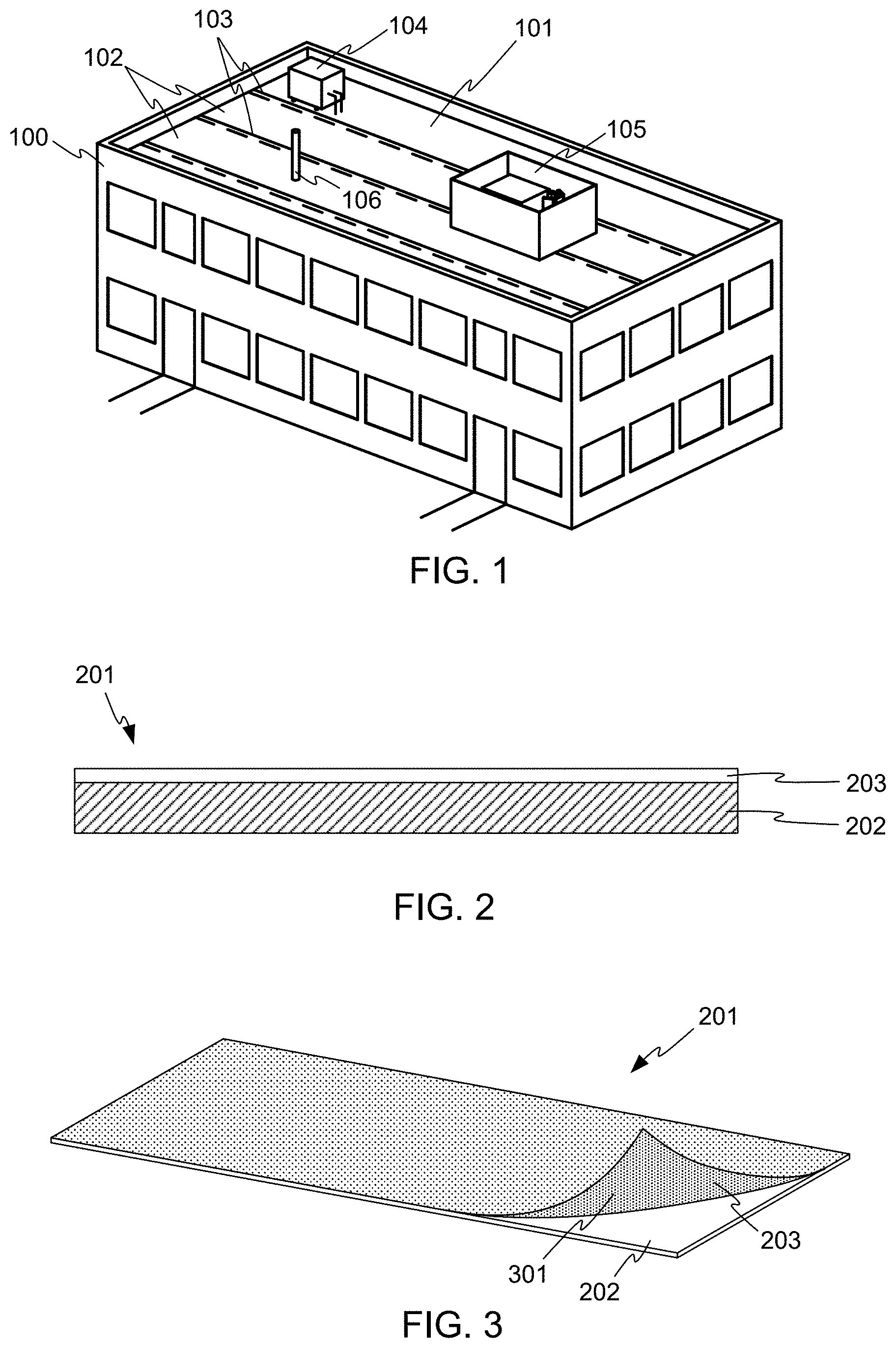
[0003] FIG. 1 illustrates a typical flat roof installation. Building 100 has a flat roof 101, covered by rows of a single ply membrane 102. The rows of single ply membrane 102 have been joined at their adjacent seams 103, so that roof 101 has been covered with a continuous waterproof barrier, other than at necessary penetrations of the roof. For example, as is typical, a number of pieces of electrical and mechanical equipment may be placed on roof 101, and may require connections to through the roof to other equipment inside building 100. In FIG. 1, air conditioning equipment 104, a cellular telephone site 105, and a plumbing drain vent 106 are illustrated, but on other roofs, other kinds of equipment may be present. On a large roof, dozens of pieces of equipment may be present, or more.
[0004] Roofing membrane 102 may preferably be white in color, to reflect sunlight and reduce the energy required to cool building 100. While roofing membrane 102 may be installed in a clean and undamaged condition, access to equipment on the roof may require that workers walk on roofing membrane 102, for example to seal roofing membrane 102 around the penetrations, or to install and connect the equipment at a later stage in the construction of building 100.
[0005] It is desirable that workers be provided access to the roof as needed, safely, and without damaging or discoloring roofing membrane 102.
BRIEF SUMMARY
[0006] According to one aspect, a roofing membrane comprises a waterproofing layer having a top major surface bounded by four edges and a release liner removably attached to and covering or substantially covering the top major surface of the waterproofing layer. The release liner has a coefficient of friction higher than the coefficient of friction of the material of the waterproofing layer.
[0007] According to another aspect, a method of applying a roofing membrane on a roof comprises laying a first row of roofing membrane on the roof, the first row of roofing membrane including a first waterproofing layer and a first release liner on top of a top major surface of the first waterproofing layer. The first release liner has a coefficient of friction higher than that of the material of the first waterproofing layer. The method further comprises laying a second row of roofing membrane on the roof, the second row of roofing membrane having a second waterproofing layer and a second release liner. The second release liner has a coefficient of friction higher than that of the material of the second waterproofing layer. The second row of roofing membrane overlaps the first row such that a bottom major surface of the second waterproofing layer contacts an uncovered strip at one edge of the top major surface of the first waterproofing layer. The method further comprises bonding the first and second rows of roofing membrane together in their area of overlap.
[0008] According to another aspect, a method of making a roofing membrane comprises providing a polymeric waterproofing layer having a top major surface, and removably attaching a release liner to the top major surface of the waterproofing layer.
[0009] The release liner has a coefficient of friction higher than that of the material of the waterproofing layer.
BRIEF DESCRIPTION OF THE DRAWINGS
[0010] FIG. 1 shows a typical flat roof installation on a building.
[0011] FIG. 2 shows a cross-section view of a roofing membrane in accordance with embodiments of the invention.
[0012] FIG. 3 shows a perspective view of the roofing membrane of FIG. 2, with a release liner partially pulled back from a waterproofing layer, in accordance with embodiments of the invention.
[0013] FIG. 4 shows a release liner according to other embodiments of the invention.
[0014] FIG. 5 illustrates a roofing membrane in accordance with other embodiments of the invention.
[0015] FIG. 6 illustrates a method of installing a roofing membrane, in accordance with embodiments of the invention.
[0016] FIG. 7 illustrates a roofing membrane in accordance with other embodiments or the invention.
[0017] FIG. 8 illustrates a method of installing a roofing membrane, in accordance with other embodiments of the invention.
[0018] FIG. 9 illustrates a roofing membrane having a release liner that has an embossed surface, in accordance with embodiments of the invention.
[0019] FIG. 10 illustrates one example technique for producing a roofing membrane in accordance with embodiments of the invention.
[0020] FIG. 11 illustrates an embossing pattern in accordance with embodiments of the invention.
[0021] FIG. 12 illustrates an embossing pattern in accordance with other embodiments of the invention.
[0022] FIG. 13 illustrates an embossing pattern in accordance with other embodiments of the invention.
[0023] FIG. 14 illustrates an embossing pattern in accordance with other embodiments of the invention.
[0024] FIG. 15 illustrates an embossing pattern in accordance with other embodiments of the invention.
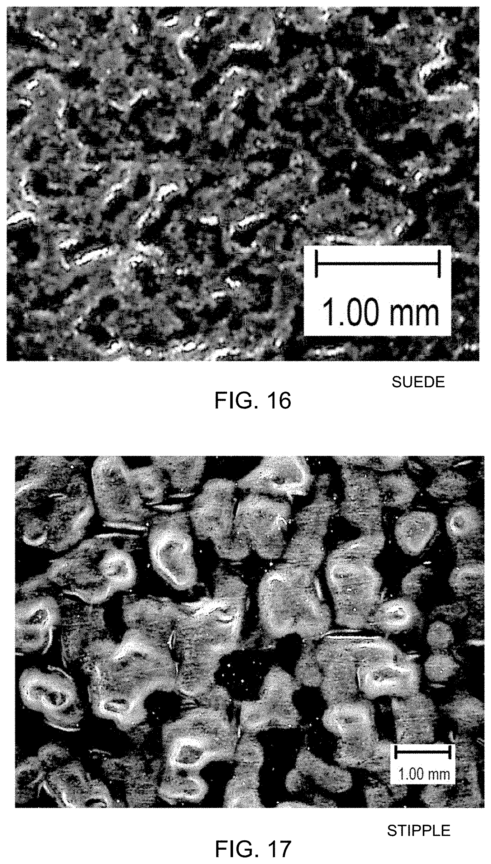
[0025] FIG. 16 illustrates an embossing pattern in accordance with other embodiments of the invention.
[0026] FIG. 17 illustrates an embossing pattern in accordance with other embodiments of the invention.
DETAILED DESCRIPTION
[0027] FIG. 2 shows a cross-section view of a roofing membrane 201 in accordance with embodiments of the invention. Roofing membrane 201 is a single ply membrane having two layers--a waterproofing layer 202 and a release liner 203.
[0028] Waterproofing layer 202 may be made of any suitable material, and in different embodiments may comprise thermoplastic polyolefin (TPO), ethylene propylene diene monomer (EPDM), polyvinyl chloride (PVC), modified bitumen, or a combination of materials. Waterproofing layer 202 may have any suitable thickness, for example between 0.020 and 0.250 inches, preferably between 0.040 and 0.125 inches. Roofing membrane 201 may be supplied in rolls of any workable size, for example rolls up to 50 feet wide or more containing 100 linear feet or more of membrane, such that membrane 201 is supplied in rectangular sheets up to 50.times.100 feet or more. The top face of the membrane may be termed the top major surface, and is bounded by four edges forming the rectangular perimeter of the sheet. Similarly, waterproofing layer 202 has a bottom major surface opposite the top major surface and intended to be placed against a roof.
[0029] While waterproofing layer 202 is shown monolithically, it may include other materials and layers. For example, waterproofing layer 202 may include an embedded reinforcing mesh made of fiberglass or other materials. In another example, waterproofing layer 202 may include an adhesive on its bottom major surface such that roofing membrane 201 is self-adhesive. In this case, another release liner (not shown) may be provided below the adhesive layer.
[0030] Smaller rolls may be provided if desired. In addition, compatible patching sheets, cap sheets, tapes, and other items may be made available for convenient installation of membrane 201 on roofs of various shapes and sizes.
[0031] The top major surface of waterproofing layer 202 is preferably light in color, for example white.
[0032] Release liner 203 is preferably a thin layer removably attached to the top major surface of waterproofing layer 202, and covering or substantially covering the top major surface. Release liner 203 is intended to be removed as a last or nearly-last step in the installation of roofing membrane 201 on a roof. Roofing membrane 201 may be installed with release liner 203 in place, and workers permitted to walk on the roof (on top of release liner 203) to complete later tasks in the construction or re-roofing of the building. For example, workers may seal joints between strips of roofing membrane 201, may seal around any penetrations of the roof, may install and connect electrical or mechanical equipment on the roof, or may perform other tasks.
[0033] Once such tasks are completed, it may be expected that foot traffic on the roof will be negligible. Near the end of the project, release liner 203 is removed, exposing the top major surface of waterproofing layer 202, in pristine or near-pristine condition. Release liner 203 substantially protects waterproofing layer 202 from dirt, scuffs, wear, or other events that might otherwise be detrimental to the integrity and reflectivity of waterproofing layer 202, and obviates the need for expensive and time-consuming cleaning of the newly-installed roof. After removal, release liner 203 may be discarded or preferably recycled.
[0034] Release liner 203 may conveniently be made of one or more layers of one or more polyolefins such as polypropylene or polyethylene, but in other embodiments may be made of any suitable material or combination of materials. Release liner 203 may be made of recycled materials, and may be recyclable once removed.
[0035] In particular, release liner 203 has a coefficient of friction greater than that of the material of waterproofing layer 202 itself. For example, a TPO membrane may have a kinetic coefficient of friction of about 0.575, and release liner 203 may have a kinetic coefficient of friction greater than 0.575, and thus may be considered to have enhanced friction characteristics, as compared with the material of waterproofing layer 202. In other embodiments, release liner 203 may have a kinetic coefficient of friction of at least 0.6, at least 0.7, at least 0.8, at least 0.9, at least 0.95, or another value. In one embodiment, release liner 203 has a kinetic coefficient of friction of about 0.965.
[0036] For the purposes of this disclosure, recited coefficients of friction are kinetic coefficients unless otherwise stated. The kinetic coefficient of friction is also sometimes known as the dynamic coefficient of friction, and is a unitless ratio computed by dividing the force required to drag one object over another by the normal force between the objects, once motion has begun. As is well known, the kinetic coefficient of friction of a material is generally lower than the static coefficient of friction. The static coefficient of friction is the unitless ratio computed by dividing the force required to start dragging motion between two objects by the normal force between them.
[0037] Also for the purposes of this disclosure, kinetic coefficients of friction were measured using a modified version of the ASTM 1894--"Standard Test Method for Static and Kinetic Coefficients of Friction of Plastic Film and Sheeting" method. In the standard ASTM 1894 test, a weighted sled is pulled across a second stationary, flat surface at a speed of 150 mm/min, and the contacting surfaces of the weighted sled and the flat surface are made of the same material under test. In the modified procedure used in this disclosure, the sled is covered in rubber and the flat surface is the release liner being tested. This is in order to find the coefficient of friction between the rubber (such as a sole of a shoe) and the liner. The test fixture used to measure the coefficient of friction was a Custom Scientific Instruments, Inc. CS-1525-007.
[0038] Release liner 203 may be removably attached to waterproofing layer 202 in any suitable way. In some embodiments, release liner 203 may be attached to waterproofing layer 202 using an adhesive such as a hot-melt adhesive, a pressure sensitive adhesive, a urethane based adhesive, an polyisoprene based adhesive, or another kind of adhesive. In some embodiments, any adhesive may be applied across the entire release liner. In other embodiments, the adhesive may be applied in bands, patches, or another pattern in which less than the entire surface of the release liner is covered, in order to reduce the amount of adhesive required or to reduce the force needed to separate the release liner from the waterproofing layer.
[0039] For example, FIG. 3 shows a perspective view of roofing membrane 201 with release liner 203 partially pulled back from waterproofing layer 202, in accordance with embodiments of the invention. The underside 301 of release liner 203 is uniformly coated with adhesive. FIG. 4 shows another embodiment, in which underside 301 of release liner 203 is coated with patches 401 of adhesive, such that less than the entire underside 301 is coated. Any other suitable partial coating technique may be used, including random splattering of the adhesive.
[0040] Any adhesive used may be environmentally friendly. For example, the adhesive may be biodegradable, or water soluble, or may have other properties for low environmental impact.
[0041] In other embodiments, water proofing layer 202 and release liner 203 may be removably attached without the use of any adhesive. For example, either or both of release liner 203 and waterproofing layer 202 may be statically charged, so that they are attached by electrostatic attraction. In some embodiments, waterproofing layer 202 and release liner 203 may simply subjected to heat and pressure during the manufacturing of roofing membrane 201, forming a temporary light attachment between the two.
[0042] In some embodiments, release liner 203 may include a tackifier in its formulation, so that it tends to cling to waterproofing layer 202 without being fully adhered. Various additives for imparting tack to the formulation of release liner 203 are available. For example, the Vistamaxx.RTM. line of polymers available from ExxonMobil includes polymers with good tack properties.
[0043] FIG. 5 illustrates a roofing membrane 501 in accordance with other embodiments. In this example embodiment, release liner 203 is split, so that it may be removed from waterproofing layer 202 in two pieces. This may allow for more convenient handling of release liner 203 during removal. Preferably, the edges of the two pieces of release liner 203 meet at a zero-width or near-zero-width slit 502, so that the upper major surface of waterproofing layer 202 remains protected.
[0044] FIG. 6 illustrates a method of installing a roofing membrane, in accordance with embodiments of the invention. A roofing membrane such as roofing membrane 201 is shown in this example. Roofing membrane 201a has been previously laid on a roof, and its release liner 203 lifted and folded back to form a flap 601 along one edge 602 of roofing membrane 201a. A second piece of roofing membrane, 201b, is unrolled and placed such that the bottom major surface of roofing membrane 201b overlaps and lies on top of the exposed portion of the top major surface of roofing membrane 201a, as shown at 603. The two roofing membranes may be joined and sealed by any suitable technique, for example by heat welding, by an adhesive pre-applied to either or both of roofing membranes 201a and 201b, or by an adhesive applied on the rooftop during installation. The overlapping area of the two roofing membranes is preferably wide enough to ensure a good seal between the membranes 201a and 201b. In some embodiments, the overlapping area may be about 2 to 6 inches wide, for example about 4 inches wide.
[0045] The flap 601 of release liner 203 folded back from roofing membrane 201a may conveniently be laid back down on top of the overlapping portion of roofing membrane 201b. In other embodiments, the flap may be cut off, or left loose. In some embodiments, release liner 203 may be perforated to allow for easy removal of flap 601.
[0046] FIG. 7 illustrates a roofing membrane 701 in accordance with other embodiments or the invention. Roofing membrane 701 is similar to roofing membrane 201 in that it includes a waterproofing layer 702 and a release liner 703. However, while release liner 703 substantially covers the top major surface of waterproofing layer 702, it does not completely cover the top major surface of waterproofing layer 702. Rather, a strip 704 of the top major surface of waterproofing layer 702 is left uncovered by release liner 703, along one edge 705 of waterproofing layer 702.
[0047] This arrangement facilitates installation of roofing membrane 701, as shown in FIG. 8. A second row of roofing membrane 701b can be overlapped and sealed to a previously-laid first row 701a without the need to remove or fold back any release liner from strip 704 along edge 705 of the first row 701a of release liner. The overlapped area shown at 803 can be sealed in any suitable manner, as discussed above.
[0048] The coefficient of friction of release liner 203 may be enhanced, for example using a chemical additive in the material of release liner 203. In some embodiments, release liner 203 may comprise a styrene block copolymer such as Kraton.RTM. styrene block copolymer available from Kraton Corporation of Houston, Tex., USA, or a Vistamaxx.RTM. polymer available from ExxonMobil Chemical Company of Spring, Tex., USA.
[0049] Methods of producing a plastic film having an enhanced coefficient of friction are given in U.S. Patent Application Publication No. 2018/0117874 of Rothbauer et al., published May 3, 2018 and titled "Reusable, Non-Adhesive Protective Cover", the entire disclosure of which is hereby incorporated by reference herein for all purposes.
[0050] As is discussed above, the coefficient of friction of a release liner embodying the invention may be enhanced by the use of an additive in the material of the release liner. In addition or alternatively, the release liner may be textured or otherwise formed, for example with raised bumps, to provide a mechanical enhancement to its friction characteristics. In one example, FIG. 9 illustrates a roofing membrane 901 having a release liner 902 that has an embossed surface, in accordance with embodiments of the invention. In this example, release liner 902 has a number of elongated bumps 903 arranged at crossing angles, creating a pattern similar to that often used on steel stair treads for enhancing traction. In other embodiments, bumps 903 may be of any suitable shape, for example round, polygonal, irregular, or another shape, and may be placed in any suitable arrangement, for example in a pattern or randomly.
[0051] In other embodiments, the pattern on the protective film may be formed by one or more of horizontal lines, vertical lines, diagonal lines, squares, or diamond patterns. Also usable are patterns generated from embossing shapes such as random rough texture, squares, inverted squares, dotlines and reversed dotlines. In other embodiments, recesses may be formed into release liner 902, rather than raised bumps.
[0052] The sizes of the raised features may range from 0.1 mm to 25 mm, and the features may be arranged in a repeating pattern that repeats every 0.1 to 25 mm or more across the release liner. He height of any raised features (or depth of any recessed features) may preferably be between 0.001 mm to 0.1 mm, although other heights may be used. The heights of bumps 903 may be exaggerated in FIG. 9.
[0053] In one preferred embodiment, the embossed pattern is made up of repeating adjacent diamond-shapes about 1.2 mm across and a height of about 0.20 mm.
[0054] Methods of producing a plastic film having an embossed surface are given in U.S. Patent Application Publication No, 2018/0117874 of Rothbauer et al., previously incorporated by reference.
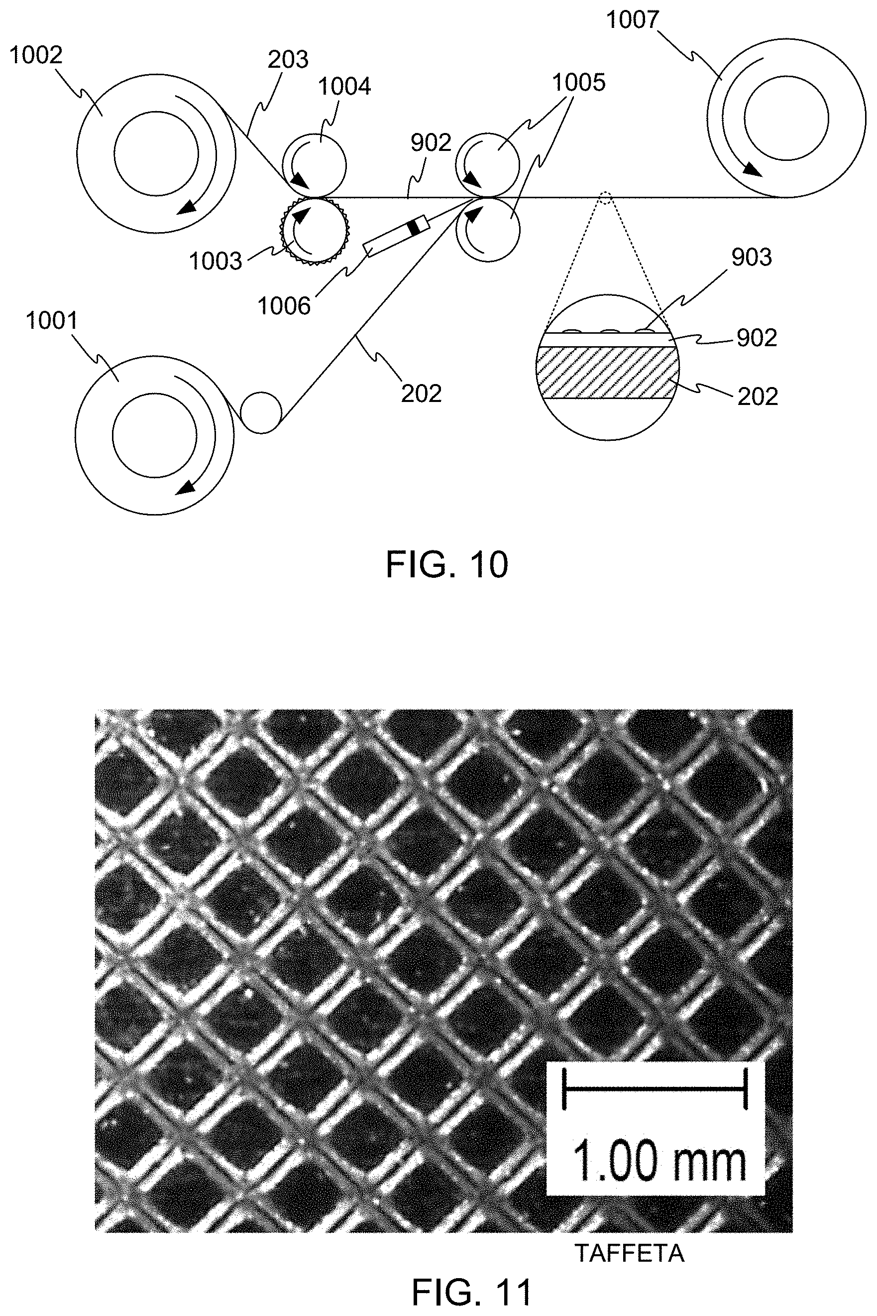
[0055] FIG. 10 illustrates one example technique for producing a roofing membrane in accordance with embodiments of the invention. In this example, both the waterproofing layer 202 and the release liner 203 have been previously fabricated and stored on rolls. A first roll 1001 of waterproofing layer 202 and a second roll 1002 of release liner 203 are mounted on shafts. Release liner 203 may optionally be fed between an embossing roller 1003 (the roughness of which is exaggerated in FIG. 10) and a rubber roller 1004, to raise bumps on release liner 203, transforming release liner 203 into an embossed release liner such as release liner 902 discussed above. Waterproofing layer 202 is also fed off of roll 1001, and waterproofing layer 202 and release liner 902 are brought together at compression rollers 1005, where release liner 902 is removably attached to waterproofing layer 202. Optionally, an adhesive may be placed between waterproofing layer 202 and release liner 902, for example by an extruder or other dispenser 1006. The completed roofing membrane is then wound onto a roll 1007 for packaging and shipment.
[0056] Within this basic framework, many variations are possible. For example, embossing roller 1003 may be omitted, so that the resulting roofing membrane is similar to un-embossed roofing membrane 201. In other embodiments, either or both of waterproofing layer 202 and release liner 203 may be fabricated, for example by extrusion, immediately before being brought together to form a complete roofing membrane. In other embodiments, waterproofing layer 202 and release liner 203 may be coextruded onto a single roller. Any workable combination of steps and processes may be used.
EXAMPLES
[0057] A number of example release liners were produced and characterized, as summarized in Table 1 below. Also included in Table 1 is a comparative reading taken from a TPO membrane having no release liner. In all of the examples of Table 1, no chemical additives or treatments were included in the release liner for the specific purpose of enhancing the friction characteristics of the release liner. The heights of the embossed features were between 20 and 250 micrometer (0.02 and 0.25 mm).
TABLE-US-00001 TABLE 1 Friction Effect of Example Release Liners Liner Emboss Static Kinetic % .DELTA. % .DELTA. Liner Material Pattern COF COF Static COF Kinetic COF Comparative TPO N/A N/A 0.688 0.575 N/A N/A Membrane - no liner 1 Nylon Taffeta 0.755 0.803 9.74% 39.69% 2 Polypropylene Diamond 0.984 0.965 42.95% 67.97% 3 Rubber Matte/Smooth 0.667 0.604 -3.12% 5.13% 4 Polypropylene Linen 0.524 0.470 -23.91% -18.28% 5 Polypropylene Orange Peel 0.482 0.390 -30.01% -32.11% 6 Polypropylene Suede 0.622 0.593 -9.67% 3.13% 7 Polyprpylene Stipple 0.699 0.665 1.60% 15.67% 8 Polypropylene Matte 0.800 0.802 16.28% 39.60% 9 Polypropylene Taffeta 0.692 0.587 0.58% 2.18% 10 Polypropylene Matte 0.793 0.784 15.26% 36.47%
[0058] The various embossing patterns are illustrated in FIGS. 11-17.
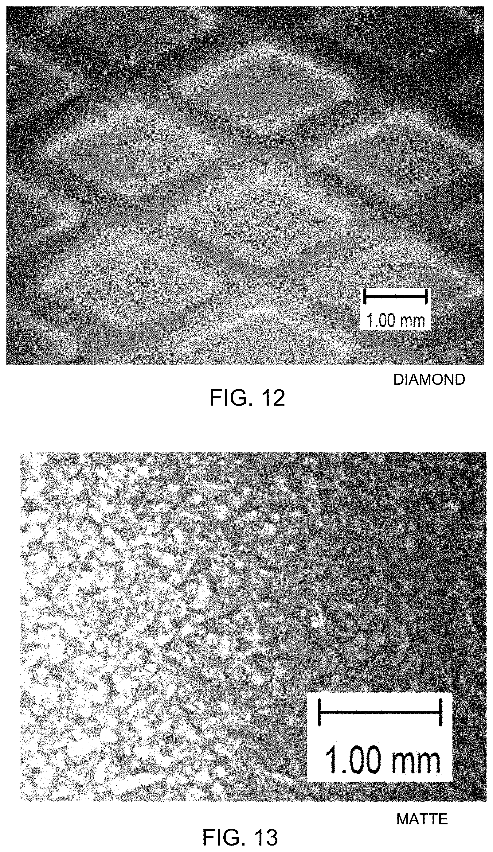
[0059] FIG. 11 illustrates an embossing pattern having intersecting embossed lines forming rectangles. In the example of FIG. 11, the rectangles are squares about 0.5 mm on a side, and are oriented at a 45-degree angle to the edges of the release liner. In other embodiments, the rectangles may be at any other orientation angle, including aligned with the edges of the release liner. Rectangles of other sizes may be used. The pattern of FIG. 11 is denoted as a "taffeta" pattern, but this name is for convenient reference only, and is not to be taken as limiting in any way.
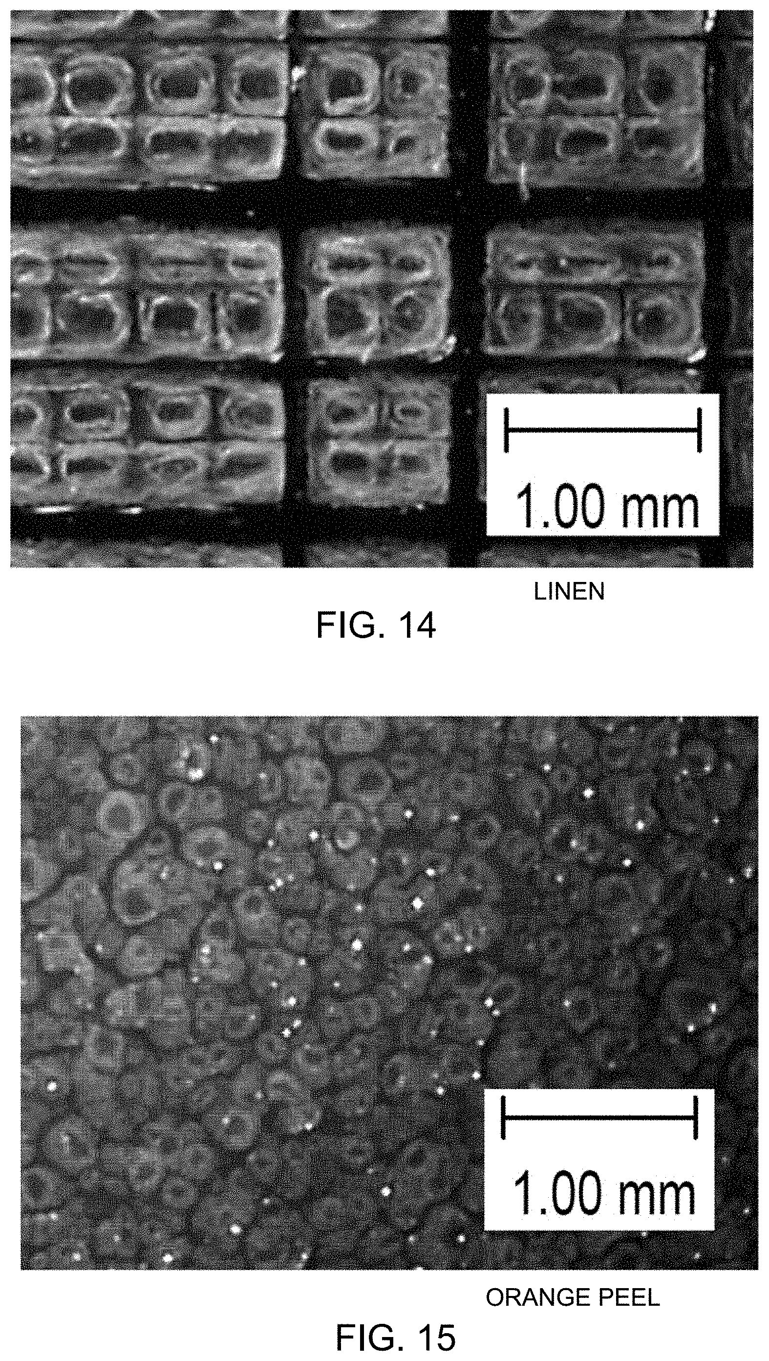
[0060] FIG. 12 illustrates an embossing pattern having intersecting embossed lines forming diamond shapes. In the example of FIG. 12, the diamond shapes are about 2.0 by 4.0 mm, with their long axis aligned with an edge of the release liner. In other embodiments, the diamond shapes may be at any other orientation angle, and may be of other sizes. The pattern of FIG. 12 is denoted as a "diamond" pattern, but this name is for convenient reference only, and is not to be taken as limiting.
[0061] FIG. 13 illustrates an embossing having small, randomly oriented embossed bumps. In the example of FIG. 13, the bumps are between about 0.1 and 0.3 mm in size. The pattern of FIG. 13 is denoted as a "matte" pattern, but this name is for convenient reference only, and is not to be taken as limiting.
[0062] FIG. 14 illustrates an embossing pattern having intersecting embossed lines forming rectangular shapes. Some of the lines are wider than others, and form a pattern of larger rectangles having dimensions of about 0.5 to 3.0 mm on each side. Within the larger rectangles, narrower lines form approximately square features about 0.3 mm on a side. The rectangular features are aligned with an edge of the release liner in FIG. 14, but other sizes or orientations may be used. The pattern of FIG. 14 is denoted as a "linen" pattern, but this name is for convenient reference only, and is not to be taken as limiting.
[0063] FIG. 15 illustrates another embossing pattern having small, randomly oriented embossed bumps. The example of FIG. 15 may be similar to the example of FIG. 13, except that the bumps are somewhat larger. The pattern of FIG. 15 is denoted as a "matte" pattern, but this name is for convenient reference only, and is not to be taken as limiting.
[0064] FIG. 16 illustrates another embossing pattern having small, randomly oriented embossed bumps. The example of FIG. 16 may be similar to the examples of FIGS. 13 and 15, except that the bumps are still larger, and are elongated so that they intertwine with each other to a degree. The pattern of FIG. 16 is denoted as a "suede" pattern, but this name is for convenient reference only, and is not to be taken as limiting.
[0065] FIG. 17 illustrates another embossing pattern having randomly oriented embossed bumps. The example of FIG. 17 may be similar to other examples, except that the bumps are still larger. In FIG. 17, the bumps are between about 0.5 and 1.0 mm across, but other sizes may be used. The pattern of FIG. 17 is denoted as a "stipple" pattern, but this name is for convenient reference only, and is not to be taken as limiting.
[0066] As is apparent from Table 1, the embossing pattern has an effect on the coefficient of friction of the release liner. A diamond pattern, for example as illustrated in FIG. 12, may achieve a coefficient of friction of up to 0.965 or more in a polypropylene release liner--an improvement of nearly 68 percent over the comparative TPO membrane having no release liner. Other embossing patterns showing the most significant friction enhancements include the "taffeta" pattern, for example as illustrated in FIG. 11, and the "matte" pattern illustrated in FIG. 13.
[0067] The invention has now been described in detail for the purposes of clarity and understanding. However, those skilled in the art will appreciate that certain changes and modifications may be practiced within the scope of the appended claims.
* * * * *
D00000
D00001
D00002
D00003
D00004
D00005
D00006
D00007
D00008
XML
uspto.report is an independent third-party trademark research tool that is not affiliated, endorsed, or sponsored by the United States Patent and Trademark Office (USPTO) or any other governmental organization. The information provided by uspto.report is based on publicly available data at the time of writing and is intended for informational purposes only.
While we strive to provide accurate and up-to-date information, we do not guarantee the accuracy, completeness, reliability, or suitability of the information displayed on this site. The use of this site is at your own risk. Any reliance you place on such information is therefore strictly at your own risk.
All official trademark data, including owner information, should be verified by visiting the official USPTO website at www.uspto.gov. This site is not intended to replace professional legal advice and should not be used as a substitute for consulting with a legal professional who is knowledgeable about trademark law.