Multi-function Railway Maintenance System
IRION; Allan ; et al.
U.S. patent application number 16/598740 was filed with the patent office on 2020-08-27 for multi-function railway maintenance system. The applicant listed for this patent is NORDCO INC.. Invention is credited to Bruce Michael BOCZKIEWICZ, Allan IRION, Kyle Matthew NEUBAUER, Justin Jerome PIPOL, Nichalos Lee SCHULTZ, William D. STRAUB.
| Application Number | 20200270819 16/598740 |
| Document ID | / |
| Family ID | 1000004839318 |
| Filed Date | 2020-08-27 |


View All Diagrams
| United States Patent Application | 20200270819 |
| Kind Code | A1 |
| IRION; Allan ; et al. | August 27, 2020 |
MULTI-FUNCTION RAILWAY MAINTENANCE SYSTEM
Abstract
A multi-function rail maintenance system is provided for performing a sequence of rail maintenance operations on a targeted portion of a railroad track, including at least two function specific modules, each module being movable along the track and having a designated number of function-specific workheads; each module including a coupling assembly for connecting the modules together and for maintaining a specific separation distance; at least one operator cab on at least one module; and a control system on at least one module associated with the at least one operator cab, and connected to each module for controlling and coordinating operation of the workheads, and for maintaining the specific separation distance.
| Inventors: | IRION; Allan; (Milwaukee, WI) ; STRAUB; William D.; (Elm Grove, WI) ; BOCZKIEWICZ; Bruce Michael; (Milwaukee, WI) ; PIPOL; Justin Jerome; (Hartland, WI) ; NEUBAUER; Kyle Matthew; (Greenfield, WI) ; SCHULTZ; Nichalos Lee; (Lindenhurst, IL) | ||||||||||
| Applicant: |
|
||||||||||
|---|---|---|---|---|---|---|---|---|---|---|---|
| Family ID: | 1000004839318 | ||||||||||
| Appl. No.: | 16/598740 | ||||||||||
| Filed: | October 10, 2019 |
Related U.S. Patent Documents
| Application Number | Filing Date | Patent Number | ||
|---|---|---|---|---|
| 62744049 | Oct 10, 2018 | |||
| Current U.S. Class: | 1/1 |
| Current CPC Class: | B61K 9/08 20130101; E01B 29/32 20130101; E01B 29/02 20130101; E01B 29/09 20130101 |
| International Class: | E01B 29/32 20060101 E01B029/32; E01B 29/02 20060101 E01B029/02; E01B 29/09 20060101 E01B029/09 |
Claims
1. A multi-function rail maintenance system for performing a sequence of rail maintenance operations on a targeted portion of a railroad track, comprising: at least two function specific modules, each module being movable along the track and having a designated number of function-specific workheads; each module including a coupling assembly for connecting the modules together and for maintaining a specific separation distance; at least one operator cab on at least one said module; and a control system on at least one said module associated with said at least one operator cab, and connected to each said module for controlling and coordinating operation of said workheads, and for maintaining said specific separation distance.
2. The system of claim 1, further including three modules, a first, puller car, a second or exchanger car and a third, spiker car so that said system is configured for performing all maintenance operation related to the removal and replacement of a rail tie.
3. The system of claim 1, wherein said function-specific workheads include workheads configured for spike pulling, anchor spreading, rail plate separation from the tie and retaining, rail tie extraction and replacement, plate setting, spike driving and anchor squeezing.
4. The system of claim 1, wherein one said module is a puller car configured for pulling spikes and spreading anchors.
5. The system of claim 4, wherein said puller car includes a spike and/or anchor retriever using a magnet for collecting withdrawn spikes and anchors and storing them in an on-car collection bin.
6. The system of claim 4, wherein said puller car is provided with a ballast broom, a spike puller, a spike broom, an anchor spreader and a discarded material reclaimer/retriever.
7. The system of claim 1, where in one said module is an exchange car configured for gripping the tie plate and holding it against the rail, lifting the rail and tie plate, extracting the existing tie, replacing a new tie and positioning the plate beneath the rail before the rail is lowered into position.
8. The system of claim 7, wherein said exchange car includes a tie exchanger mechanism, a supply of new ties and a tie handler crane.
9. The system of claim 8, wherein said control system is configured for operationally coordinating said tie exchanger mechanism and said tie handler crane.
10. The system of claim 1, wherein one said module is a spiker car configured for spike driving and anchor squeezing.
11. The system of claim 10, wherein said spiker car is configured for ballast tamping.
12. The system of claim 1, wherein said spiker car is provided with a tamper apparatus, a spiker apparatus, a rail tie nipper, a gauger and an anchor squeezer.
13. The system of claim 1, wherein each said module includes a main frame and at least one independently movable workhead frames being movable between a retracted or travel position, and a lowered or working position in operational relation to the track.
14. The system of claim 1, wherein each said module is at least one of self-propelled or towable by another drive source.
15. The system of claim 1 wherein said control system is constructed and arranged so that said modules are flexibly movable relative to each other in a working condition, and are fixed relative to each other in a travel condition.
16. The system of claim 1, wherein said control system is configured for tracking the status of a targeted tie, including recording location, maintenance steps performed, and any steps still outstanding, and displaying said tracked status for view by an operator.
17. The system of claim 1, wherein said control system is constructed and arranged for measuring the distance between the modules, and from said system to the next tie requiring a maintenance operation to be performed by the system overall, as well as by the particular modules, and once the operator initiates movement of said system, said control system automatically stops at the next optimal location.
18. A rail maintenance module, comprising: a main frame; a ballast broom connected to said frame; a spike puller connected to said frame; a spike broom connected to said frame; an anchor spreader connected to said frame; a discarded material retriever connected to said frame; and at least one of said ballast broom, said spike puller, said spike broom, said anchor spreader, and said discarded material retriever being movable relative to said frame between a retracted, travel position, and a lowered operational position located closer to a track upon which maintenance is performed.
19. A rail maintenance module, comprising: a main frame, connected to the main frame are; a tamper apparatus; a spiker apparatus; a rail tie nipper; a gauger; an anchor squeezer; and at least one of said tamper apparatus, said spiker apparatus, said rail tie nipper, said gauger and said anchor squeezer being movable relative to said frame between a retracted, travel position, and a lowered operational position located closer to a track upon which maintenance is performed.
Description
RELATED APPLICATION
[0001] This application is a Non-Provisional of, and claims 35 USC 119 priority from, U.S. Provisional Application Ser. No. 62/744,049, filed Oct. 10, 2018, the contents of which are incorporated by reference.
BACKGROUND
[0002] The present invention relates generally to railway maintenance equipment, and more specifically to improved railway maintenance equipment in which the maintenance tasks are more effectively coordinated.
[0003] In conventional railway maintenance operations, groups or so-called "gangs" of maintenance equipment are compiled for performing a designated sequence of rail maintenance operations. These operations include spike pulling, anchor spreading, rail lifting, tie plate removal, tie extraction, tie insertion, tie plate insertion, rail lowering, spike driving, anchor squeezing, ballast regulating, and/or track leveling. Typically, such tasks are each performed by designated, task-specific, self-propelled railway maintenance machines, each having at least one operator on board for performing the designated maintenance operation, as well as controlling the movement of the machine along the track, and in coordination with other machines in the gang. The machines are positioned along the track in the order of the needed performance of the designated maintenance task.
[0004] A drawback of the conventional practice described above is that each of the many machines in the gang needs to be maintained, and as such a designated inventory of parts should be on hand for each, task-specific machine. Further, each conventional machine in the gang has a designated operator, trained for performing a very repetitive task, which often becomes monotonous for the operator.
[0005] Another design factor of railway maintenance machinery is that railroads are focused on reducing the number of maintenance personnel, as well as on reducing the number of machine parts being retained in inventory in the event of machine breakdowns. As is well known in the art, the breakdown of one machine in the gang often brings a halt to the entire railway maintenance operation.
[0006] Thus, there is a need for an improved railway maintenance system that addresses the above-listed drawbacks of conventional railway maintenance machinery.
SUMMARY
[0007] The present multi-function rail maintenance system is designed to consolidate rail maintenance functions, so that a single or fewer number of operator-controlled machines do the maintenance work that is now performed by multiple, independent, task-oriented maintenance machines. Thus, a feature of the present machine or system is a reduction in labor due to fewer individual machines. Also, operators can perform multiple functions, which is not available using conventional, single-task maintenance vehicles.
[0008] In a preferred embodiment, the present system is constructed and arranged so that rail tie replacement is performed by a connected series of working modules or function cars, each module being configured for performing at least one rail maintenance operation, such as but not restricted to spike pulling, anchor spreading, rail plate separation from the tie and retaining, rail tie extraction and replacement, plate setting, spike driving, anchor squeezing and ballast tamping. Function-oriented workheads are supplied to each module for providing enhanced efficiency of the system compared to the traditional use of function-specific independent railway maintenance vehicles or machines. Using the present system, tie replacement is performed on a more continuous and efficient manner than is available using the conventional railway maintenance equipment.
[0009] In an embodiment, the present system is provided using three modules, a first or puller car is configured for pulling spikes and spreading anchors. The number of modules is contemplated as varying to suit the application. An optional feature of this car is a spike and/or anchor retriever using a magnet for collecting withdrawn spikes and anchors and storing them in an on-car collection bin. Suitable conveyors are also included for moving the collected materials from the track to the bin. In a preferred embodiment, the puller car is provided with a ballast broom, a spike puller, a spike broom, an anchor spreader and a discarded material reclaimer/retriever.
[0010] A second or exchange car is configured for lifting the rail, gripping or grasping the tie plate and holding it against the rail, extracting the existing tie, replacing a new tie and positioning the tie plate beneath the rail before the rail is lowered into position. This second car features a tie exchanger mechanism, a supply of new ties and a tie handler crane, both of which are operationally coordinated.
[0011] A third or spiker car is configured for spike driving, anchor squeezing and optionally, ballast tamping. In a preferred embodiment, the spiker car is equipped with a tamper apparatus, a spiker apparatus, a rail tie nipper, a gauger and an anchor squeezer.
[0012] Each module or car preferably includes a main frame and independently movable workhead frames, so that, depending on the function needed at a particular time, workheads are movable from a retracted, travel or storage position, to an operational position located closer to the track.
[0013] Each module or car is contemplated as being self-propelled or alternately, towable by another module or by a locomotive or other drive source. In the latter example, the modules are towable in the manner of conventional rail cars. When multiple modules are connected, they are operated by a single operator controlling speed and braking on the track. Both air and hydraulic braking systems are contemplated for each module. Another feature is that each module is optionally loadable upon a standard rail flat car for transport between work locations.
[0014] Included in the present system is a control system located on at least one of the modules, that coordinates the automatic functions of each workhead. The respective modules are connected to each other by cables and/or wirelessly.
[0015] Also, the control system tracks the status of a targeted tie, including recording location, maintenance steps performed, and any steps still outstanding. The status of these steps is visible to an operator on a display located in at least one operator cab. In the preferred embodiment, each module has an operator cab including a connection to the control system and at least one display, although a reduced number of cabs is contemplated.
[0016] Another feature of the control system is that it measures the distance between the modules, and from the collected system to the next tie requiring a maintenance operation to be performed by the system overall as well as by the particular modules or function cars. Once the operator initiates movement of the system, the control system automatically stops at the next optimal location.
[0017] In addition, the present control system uses location technology, such as GPS and/or cameras, to monitor the position of targeted ties needing replacement. Also, the location technology is connected to computers for coordinating the positioning of the frame(s) and the operation of the workheads to perform the required tasks in sequence so that the frame(s) maintain a constant forward motion along the track.
[0018] It is also contemplated that the present control system is configured for monitoring and managing the workheads so that multiple workheads perform distinct functions simultaneously on spaced targeted ties. Accordingly, a user can optionally perform multiple tasks sequentially on a single targeted tie, or perform multiple tasks on a spaced sequence of targeted ties.
[0019] Another feature of the present system is that, when provided in multiple car or frame format, the couplings of adjacent cars/frames are adjustable and computer controlled to accommodate for different work speeds. For example, the distance between a faster operating car and a slower operating car can be extended to account for the longer time needed for the slower working car to complete the work on its target tie to keep up with the faster working car. The movement between cars allows multiple cars to perform work on multiple ties simultaneously. Without this the work heads would not have enough movement to align to the ties without lengthening the cars. The functions performed on each tie will vary based on the type of tie (wood or concrete) and the fastening systems (spikes, screws, clips etc.) The present system is modifiable as to the work heads required for the type of tie and fastening system.
[0020] In another embodiment, a rail maintenance module includes a main frame, a ballast broom connected to the frame, a spike puller connected to the frame, a spike broom connected to the frame, an anchor spreader connected to the frame, a discarded material retriever connected to the frame, and at least one of the ballast broom, the spike puller, the spike broom, the anchor spreader, and the discarded material retriever being movable relative to the frame between a retracted, travel position, and a lowered operational position located closer to a track upon which maintenance is performed.
[0021] In still another embodiment, a rail maintenance module includes a main frame, connected to the main frame are a tamper apparatus, a spiker apparatus, a rail tie nipper, a gauger, an anchor squeezer. At least one of the tamper apparatus, the spiker apparatus, the rail tie nipper, the gauger and the anchor squeezer are movable relative to the frame between a retracted, travel position, and a lowered operational position located closer to a track upon which maintenance is performed.
BRIEF DESCRIPTION OF THE DRAWINGS
[0022] FIG. 1 is a top front perspective view of a first, puller car of the present multi-car rail maintenance system;
[0023] FIG. 2 is a rear view of the puller car of FIG. 1;
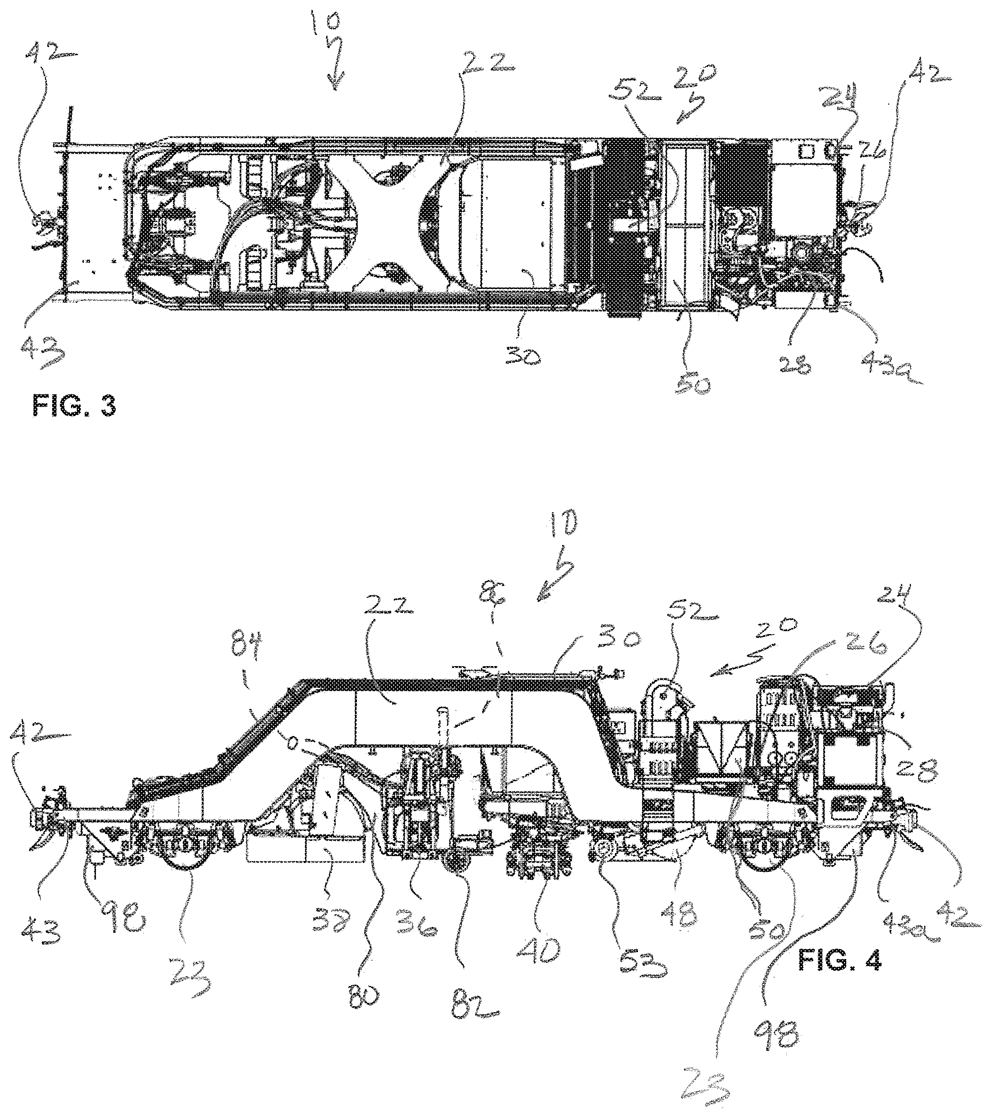
[0024] FIG. 3 is a top view of the puller car of FIG. 1;
[0025] FIG. 4 is a side view of the puller car of FIG. 1;
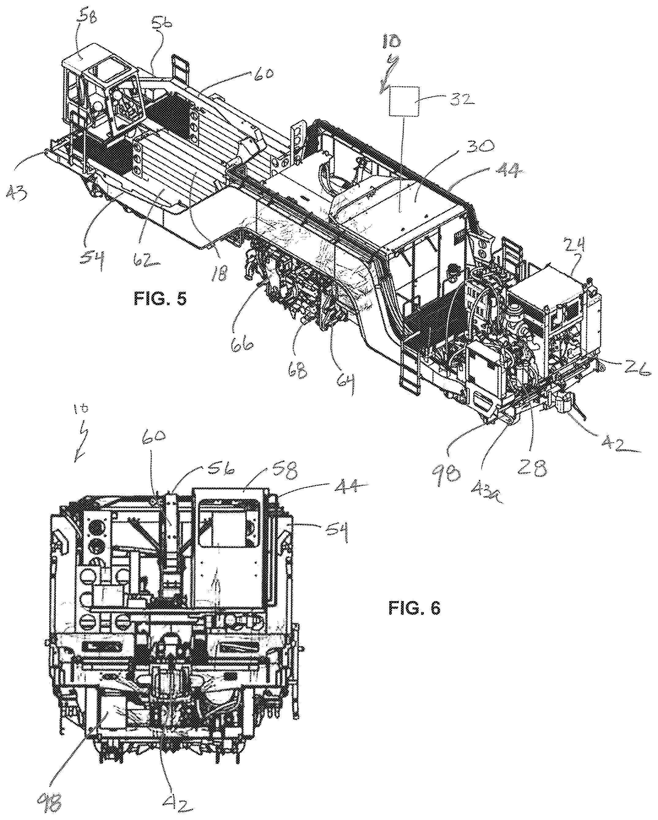
[0026] FIG. 5 is a top perspective view of a second, exchanger car of the present multi-car rail maintenance system;
[0027] FIG. 6 is a front view of the exchanger car of FIG. 5;
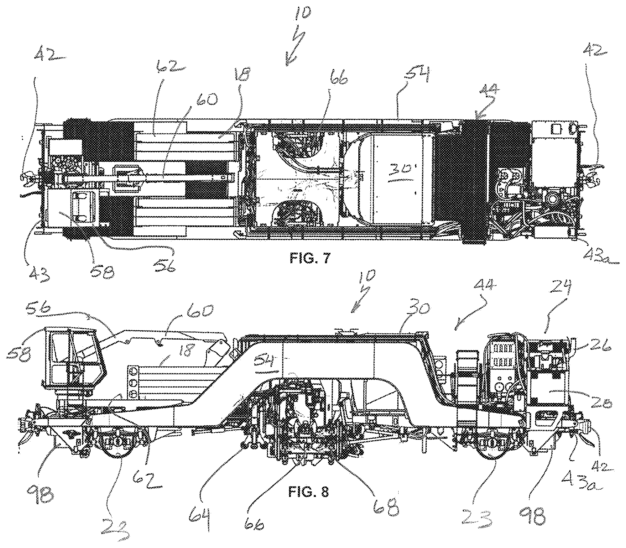
[0028] FIG. 7 is a top view of the exchanger car of FIG. 5;
[0029] FIG. 8 is a side view of the exchanger car of FIG. 5;
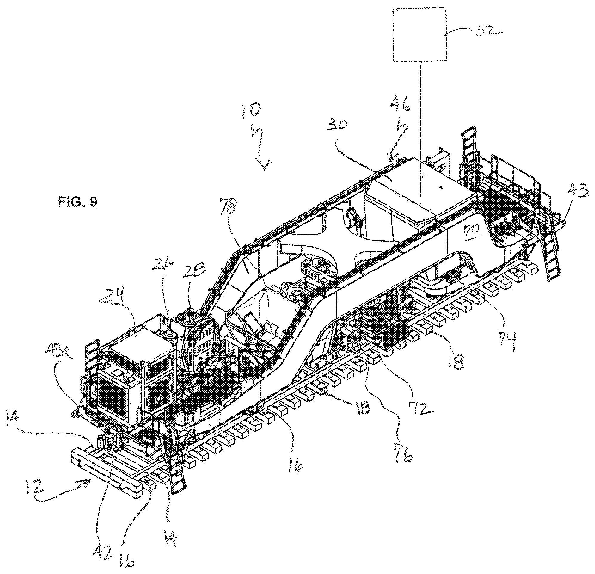
[0030] FIG. 9 is a top perspective view of a third, spiker car of the present multi-car rail maintenance system;
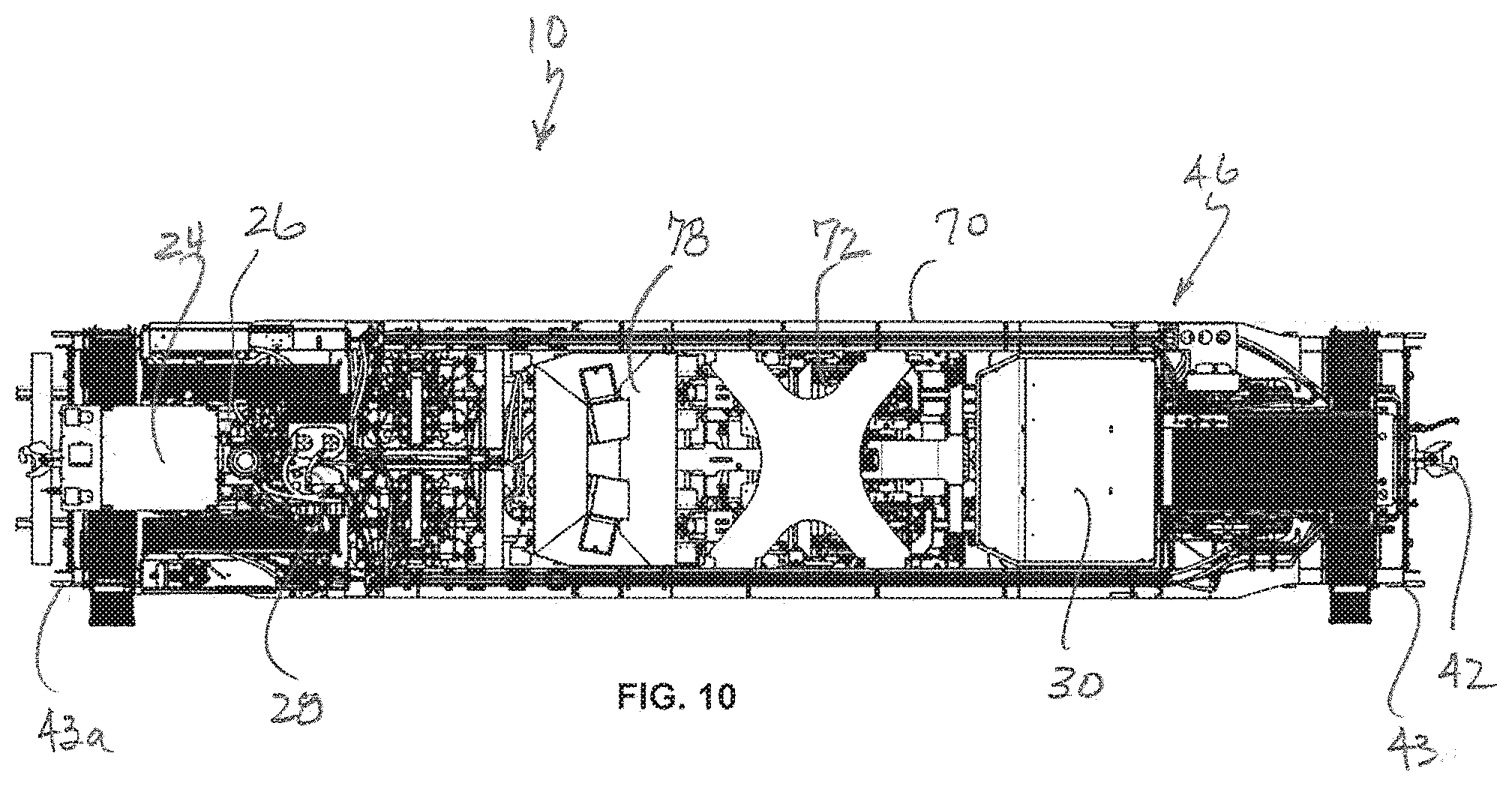
[0031] FIG. 10 is a top view of the spiker car of FIG. 9;
[0032] FIG. 11 is a front view of the spiker car of FIG. 9,
[0033] FIG. 12 is a side view of the spiker car of FIG. 9;
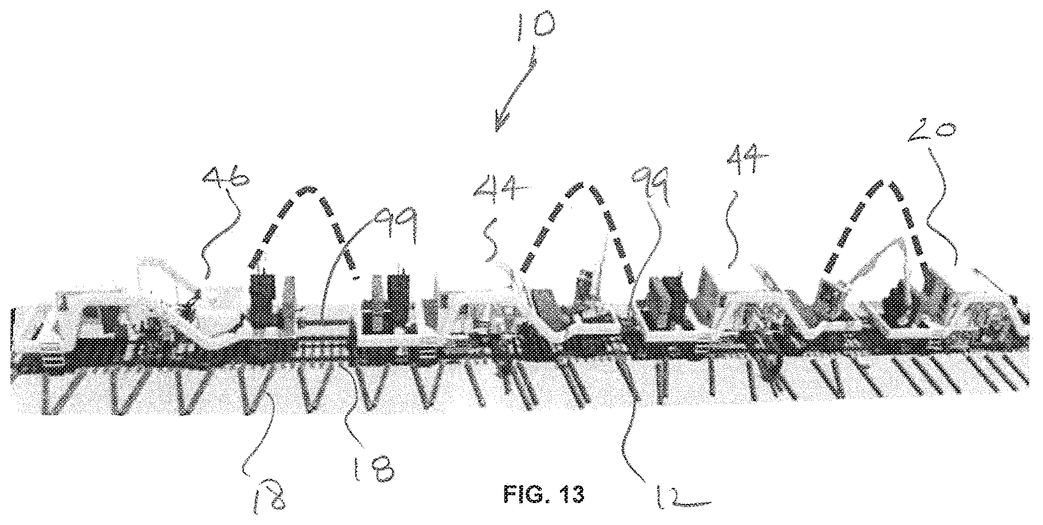
[0034] FIG. 13 is a top perspective view of the assembled puller, exchanger and spiker cars of the present rail maintenance system;
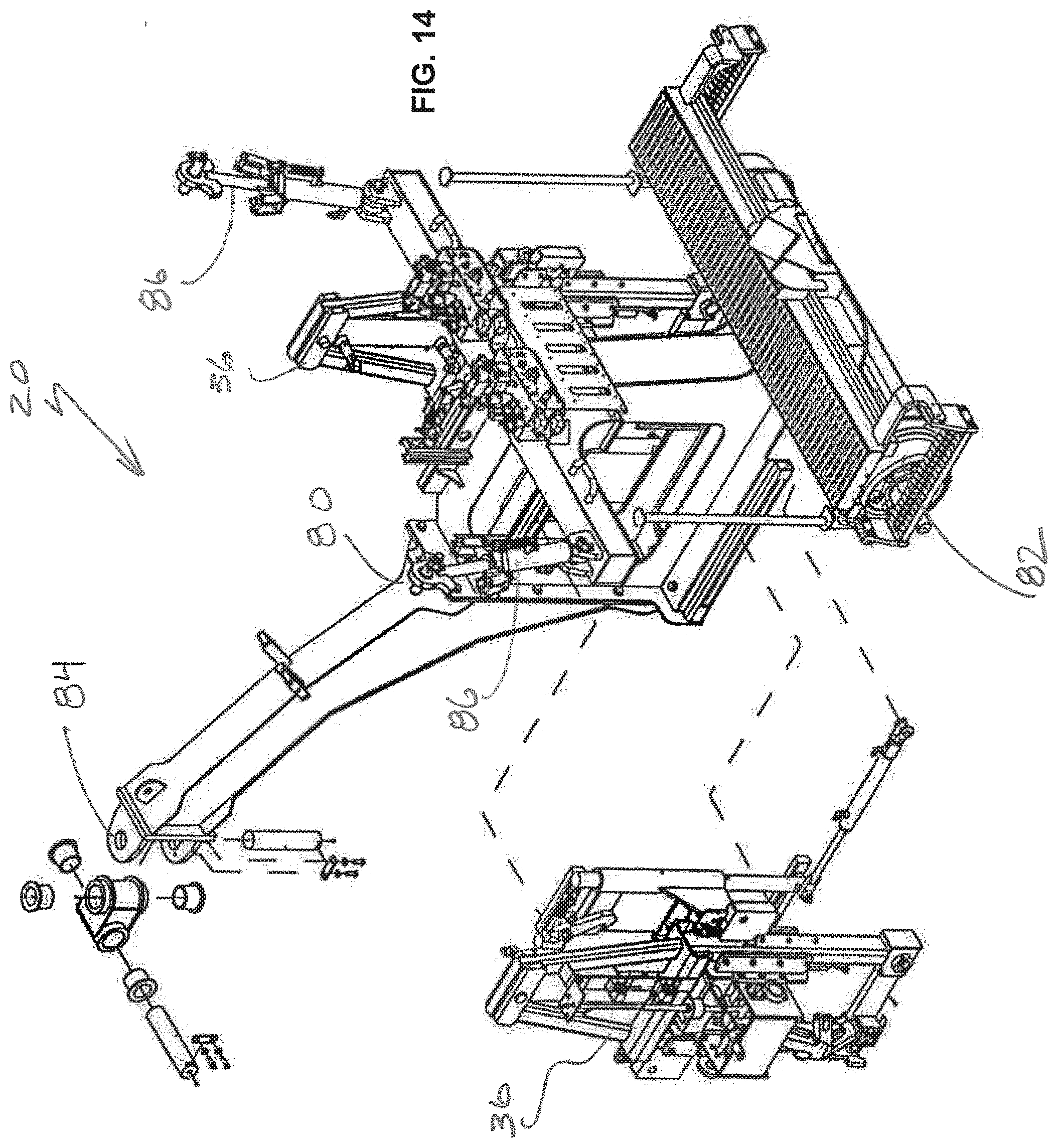
[0035] FIG. 14 is a top perspective view of a workhead subframe used with the puller car of FIGS. 1-4;
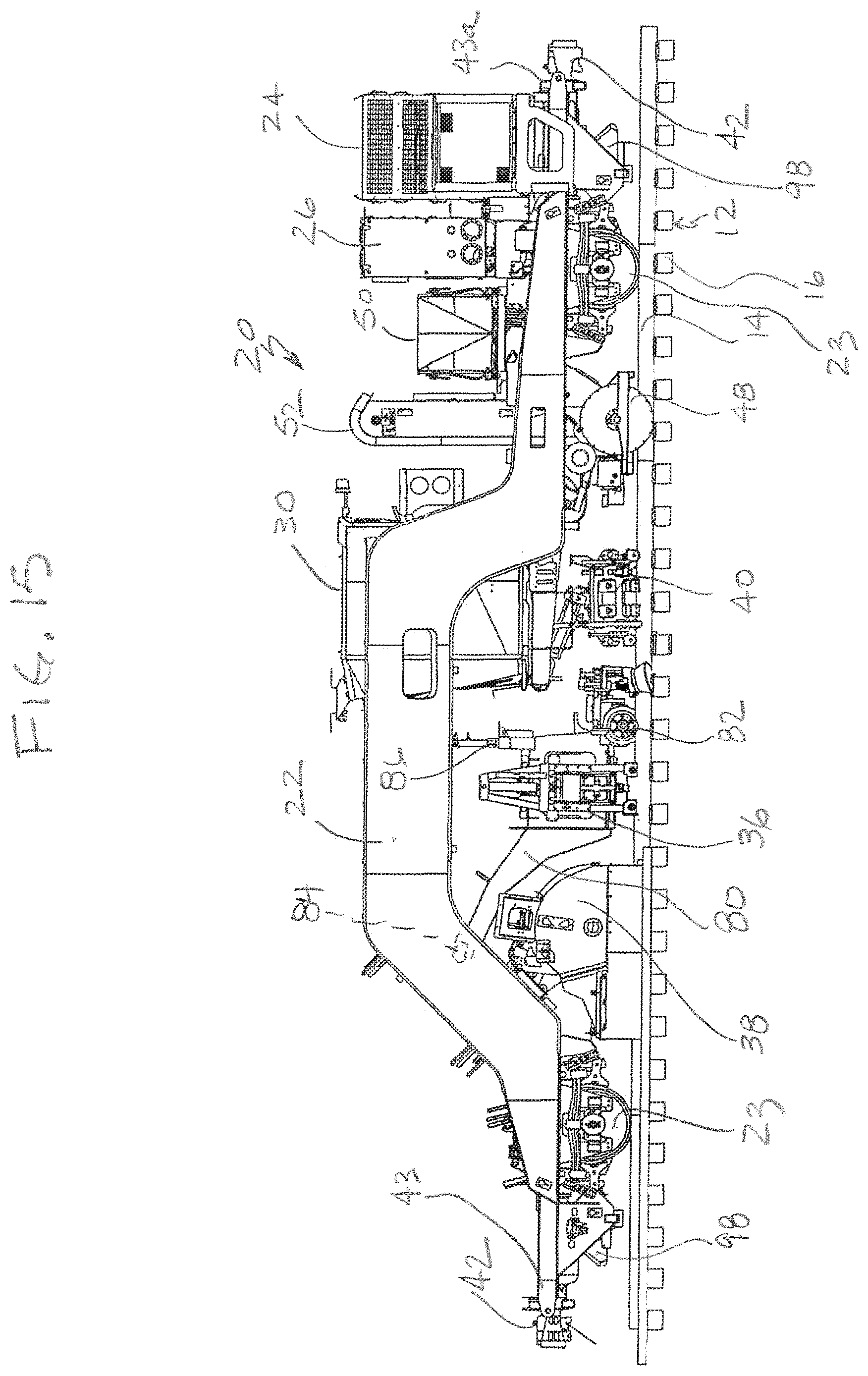
[0036] FIG. 15 is a side view of the puller car of FIGS. 1-4 showing the workhead subframe of FIG. 14 in a working position;
[0037] FIG. 16 is a side view of the puller car of FIGS. 1-4 showing the workhead subframe of FIG. 14 in a travel position;
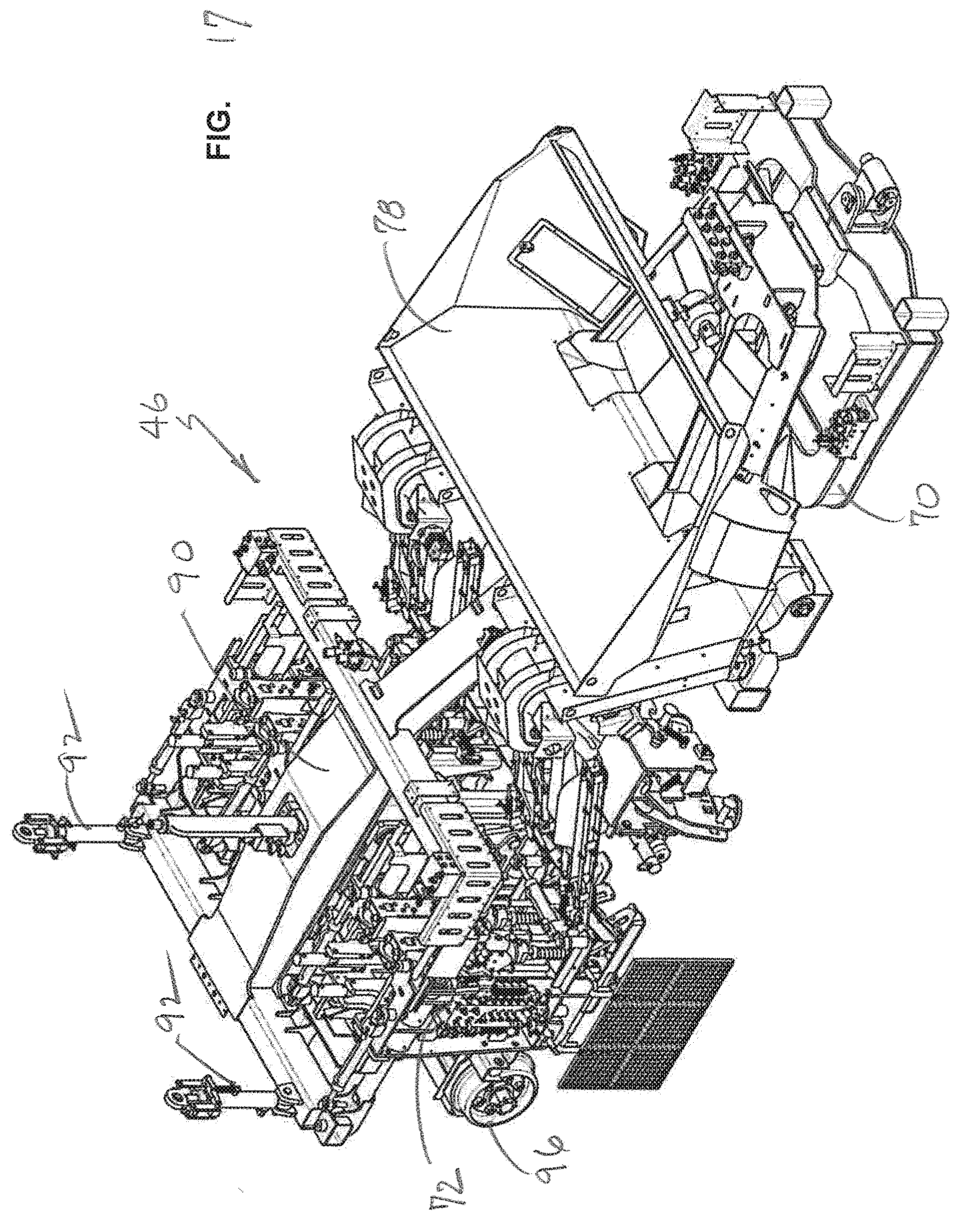
[0038] FIG. 17 is a top perspective view of a workhead subframe used with the spiker car of FIGS. 9-12;
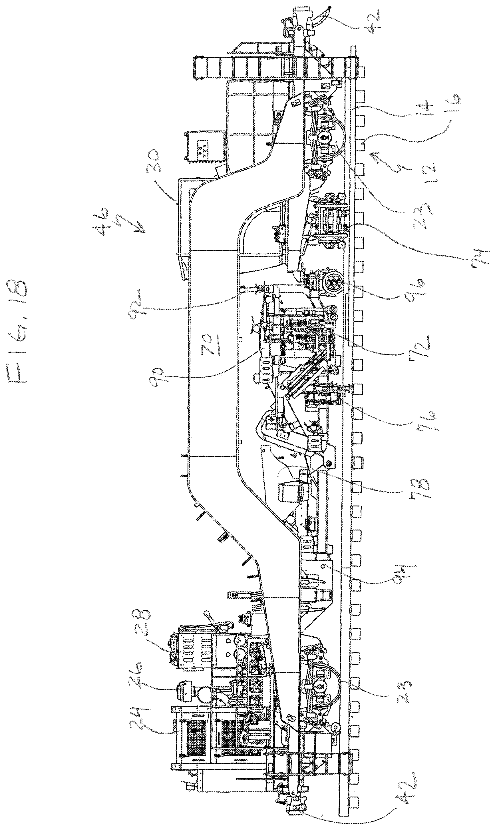
[0039] FIG. 18 is a side view of the spiker car of FIGS. 9-12 showing the workhead subframe of FIG. 17 in a working position; and
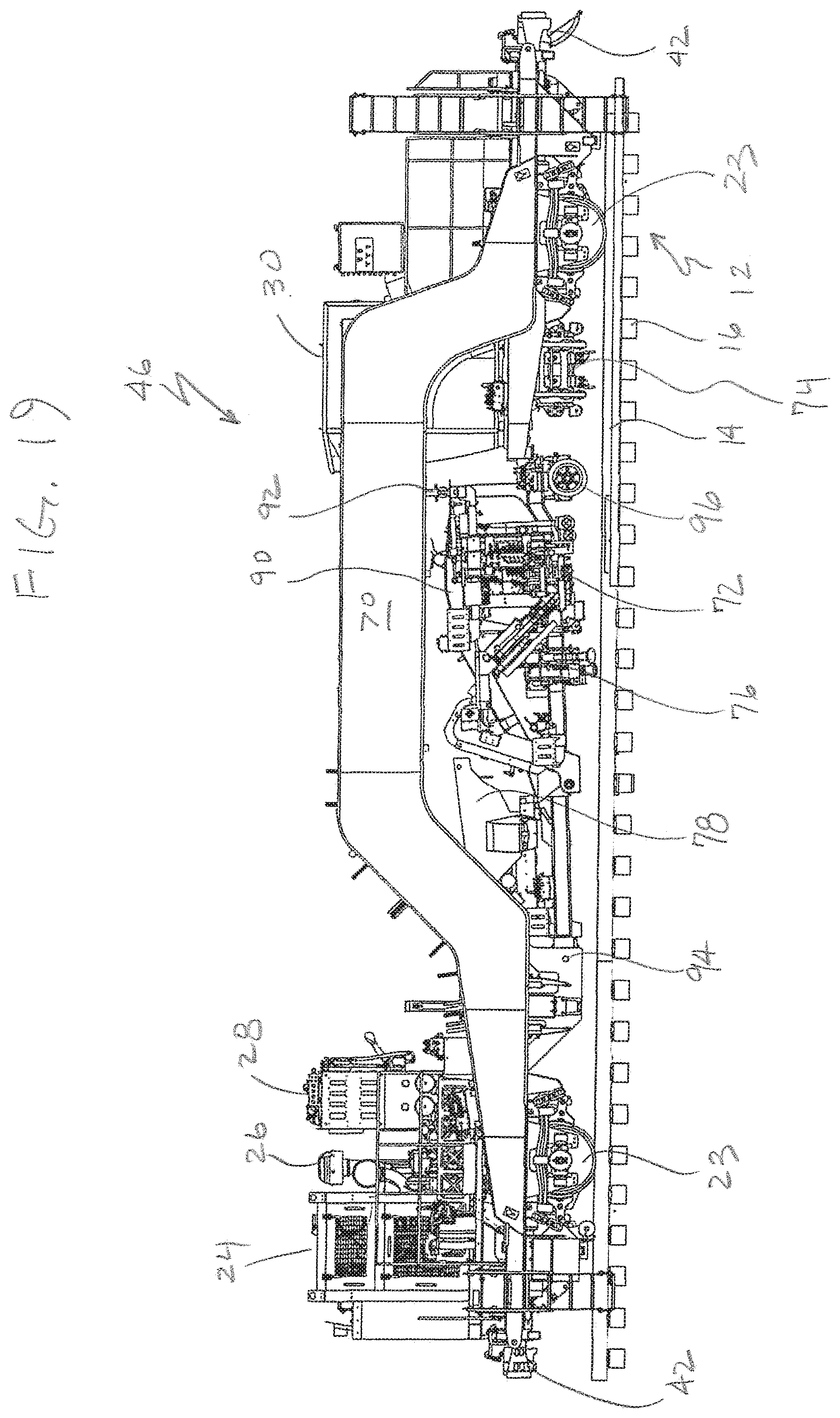
[0040] FIG. 19 is a side view of the spiker car of FIGS. 9-12 showing the workhead subframe of FIG. 17 in a travel position.
DETAILED DESCRIPTION
[0041] Referring now to FIGS. 1-4, 9 and 13, the present multi-function rail maintenance system is generally designated 10, is constructed and arranged for performing a sequence of rail maintenance operations on a track 12 (FIG. 9) made up of parallel rails 14 resting on tie plates 16 placed on transverse rail ties 18. The rails 14 and the tie plates 16 are held respectively to the rail tie plates and the ties 18 through the use of rail fasteners, typically cut spikes, screws or the like (not shown). As is known in the art, rail anchors are secured to the rails 14 near the ties 18 to maintain track alignment. A main feature of the present rail maintenance system 10 is that, through the use of coordinated, function-specific, modules or work cars, a complete rail maintenance operation, such as but not limited to the replacement of rail ties 18, is accomplished by a single maintenance system. As such, these maintenance tasks are performed more efficiently than using gangs of single-function maintenance equipment, which is the conventional practice.
[0042] In the present system 10, a plurality of function-specific modules or cars preferably including three such cars, is movable along the track 12 by being self-propelled, or alternately, towable by a locomotive or other drive source. The number of cars may vary to suit the application.
[0043] A first module or puller car 20 includes a main frame 22 configured for travelling the track 12 on standard rail wheels 23, a power source 24 including an engine 26 and a hydraulic system 28. As is known in the art, the power source 24 is used for propelling the car 20 along the track 12. If the engine 26 is not used for propulsion, the puller car 20 is towable along the track 12. At least one operator's cab 30 houses an operator and at least part of a control system 32 (schematic), including at least one display monitor 34.
[0044] Included on the puller car 20 is at least one, and preferably a plurality of function-specific workheads. While it is contemplated that the number and function of the workheads may vary to suit the situation, in the preferred embodiment, the puller car 20 includes a spike puller 36, a tie broom 38, and an anchor spreader 40. A suitable spike puller 36 is disclosed in commonly-assigned U.S. Pat. No. 4,538,793 which is incorporated by reference. Spike pulling technology is well known in the art. The tie broom 38 includes a powered, rotating brush used to remove stray ballast from the ties 18 prior to performing the maintenance operation. A suitable anchor spreader 40 is disclosed in commonly-assigned U.S. Pat. No. 8,522,688 which is incorporated by reference.
[0045] The puller car 20 is equipped with a coupling assembly 42 at each of two ends 43, 43a of the main frame 22. Included on the coupling assembly 42 is an apparatus for connecting the car 20 to adjacent modules, and connectors associated with a winch apparatus, described below for maintaining tension on ropes connecting adjacent modules for suspending conductor cables above the ground.
[0046] In the preferred system, and referring to FIG. 13, there are at least three modules, the first, puller car 20, a second, exchanger car 44 and a third, spiker car 46 so that system is configured for performing all maintenance operations related to the removal and replacement of a rail tie 18. In FIG. 13, two exchanger cars 44 are shown. The control system 32 is connected to each module 20, 44, 46 for controlling and coordinating operation of the workheads 36, 38, 40 as well as others described below, and for maintaining a specific separation distance between the modules.
[0047] Referring again to FIGS. 1-4, another feature of the puller car 20 is an optional discarded material or spike and/or anchor retriever using a magnet 48 (FIG. 4) for collecting withdrawn spikes and anchors and storing them in an on-car collection bin 50. A suitable conveyor 52 moves the collected spikes and anchors to the bin 50. Also, a spike broom 53 is provided for moving pulled spikes out of the way from the rails 14 to a position where they are accessed by the magnet 48, preferably provided as at least one rotating magnetic drum.
[0048] Referring now to FIGS. 5-8, the second module or exchanger car 44 is shown in greater detail. Components shared with the puller car 20 are designated with like reference numbers. As is the case with the puller car 20, the exchanger car 44 includes a main frame 54, a power source 24 including an engine 26 and hydraulic system 28, as well as an operator cab 30 with the control system 32. As far as function-specific workheads, the exchanger car 44 features a tie handler 56 which is basically an operator-controlled crane with a designated cab 58 and a boom 60 used for moving rail ties 18 to and from tie storage areas along the track 12 (FIG. 13), or in some cases to and from a storage area 62. In addition, the exchanger car 44 features a rail lifter 64 used for lifting the rail 14 in the area where the tie 18 is being extracted, and a tie exchanger 66. A suitable tie exchanger 66 is disclosed in commonly-assigned U.S. Pat. No. 6,463,858 which is incorporated by reference.
[0049] Just before the rail 14 is lifted, the tie plate handler 68 grips the tie plate 16 and holds it against the rail. Once the rail 14 and the tie plate 16 are lifted, the tie exchanger 66 grabs an end of the target tie 18 to be replaced, pulls it normally relative to the rails 14, and places the old tie on the field side of the track 12. The tie handler 56 is provided for positioning new ties 18 within a desired target area in relation to an extraction point where the old tie 18 is removed from the track 12 by the tie exchanger 66 as disclosed in U.S. Pat. No. 10,081,917 which is incorporated by reference. As seen in FIG. 13, new ties 18 are laid out along the track 12 prior to the maintenance operation. The objective is to place the new ties 18 close to the place where they will be inserted into the track 12, but leaving room for the extraction of the old tie by the tie exchanger 66.
[0050] A plate handler 68 is another workhead located on the exchanger car 44. As is known in the art, the plate handler 68 grabs the tie plate 16 from the tie 18 to be extracted, and in this case holds the tie plate to the rail 14 that has been raised by the rail lifter 64. A suitable rail tie plate handler 68 is shown in U.S. Pat. No. 9,777,439 which is incorporated by reference. The exchanger car 44 is also equipped with the coupling assembly 42 described above in relation to the puller car 20.
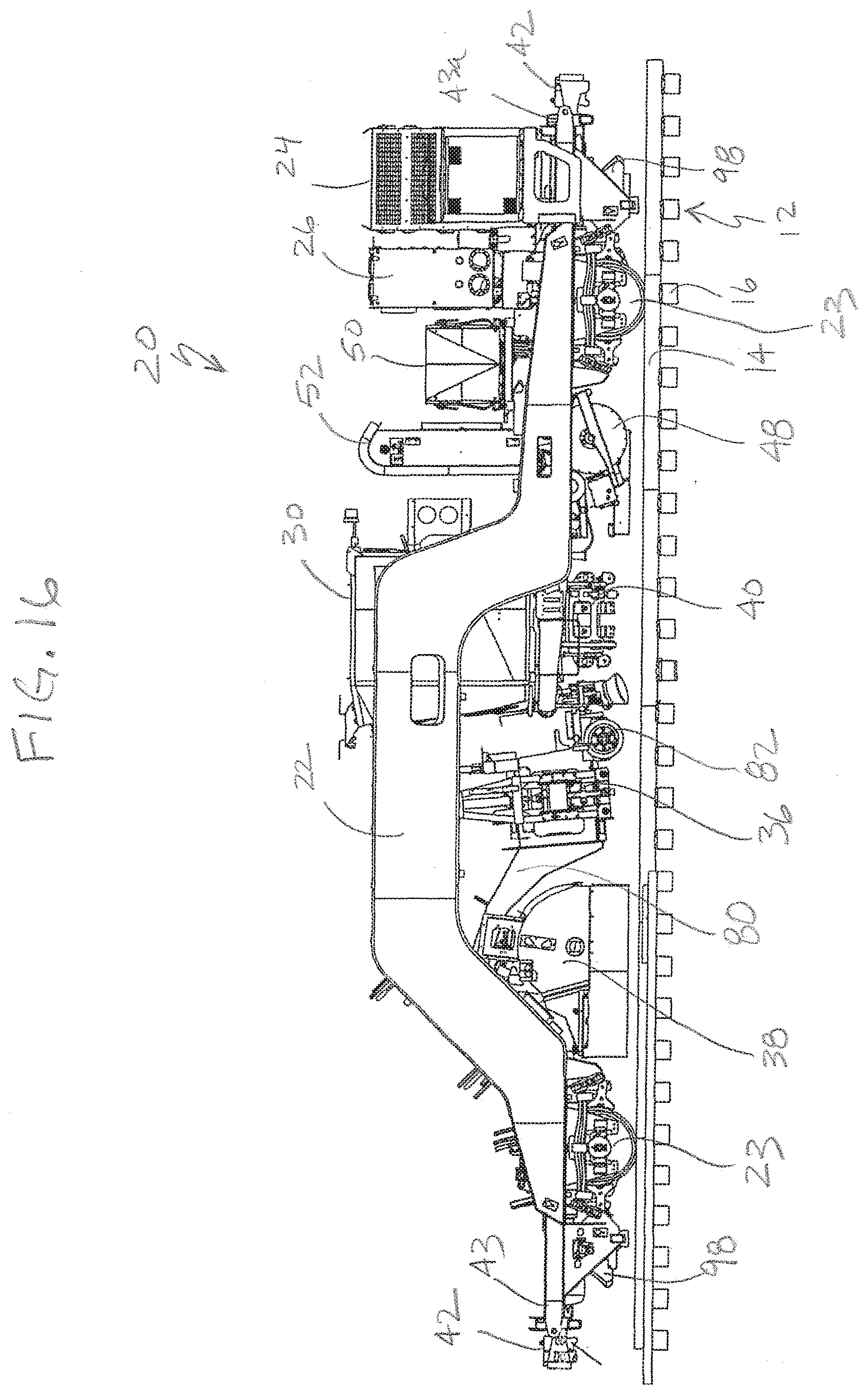
[0051] Referring now to FIGS. 9-12, the third module or spiker car 46 is shown in greater detail. Features shared with the cars 20 and 44 are designated with identical reference numbers. As is the case with the cars 20 and 44, the spiker car 46 has a main frame 70. Main functions of the spiker car 46 are spike driving and anchor squeezing, which are accomplished respectively by a spiker or spike driving workhead 72, and an anchor squeezing workhead 74. Suitable spike driving workheads are described in commonly-assigned U.S. Pat. Nos. 4,777,885 and 9,771,690, which are incorporated by reference. A suitable anchor squeezer 74 is described in commonly-assigned U.S. Pat. No. 8,522,688 which is incorporated by reference. A preferred optional workhead is a tamper apparatus 76. A suitable tamper apparatus 76 is described in commonly-assigned U.S. Pat. No. 9,731,324 which is incorporated by reference.
[0052] As is known in the art, the ballast tamper apparatus 76 is used to move the rock ballast so that the newly inserted rail tie 18 is adequately supported and that the track 12 is level at that point. Another feature of the third, spiker car 46 is a bulk spike storage bin 78 used to store and preferably deliver spikes to the spiker workhead 72. A suitable spike storage bin 78 is disclosed in commonly-assigned U.S. Pat. No. 7,216,590 which is incorporated by reference. Other optional workheads provided to the spiker car 46 include a rail tie nipper and a gauger.
[0053] For all of the workheads described above for each of the modules 20, 44 and 46, it is contemplated that many of the workheads, especially the spike puller 36, the tie broom 38, the anchor spreader 40, the tie exchanger 66, the spike driver 72, the anchor squeezer 74 and the tamper apparatus 76 include at least one independently movable workhead frame that is movable between a retracted or travel position, and a lowered or working position in operational relation to the track 12.
[0054] Referring now to FIGS. 4 and 14-16, in one embodiment of the puller car 20, the spike puller 36 is mounted on a workhead subframe 80 that is movable relative to the main frame 22 between an operational position (FIGS. 4 and 15) where the subframe is in contact with the rails 14, and a retracted or travel position (FIG. 16), which lifts the subframe away from the track 12 for travel purposes when the system 10 moves between worksites. The subframe 80 has at least one pair of rail wheels 82 which guide the subframe 80 along the track 12 in the lowered position, and also is pivotally connected to the main frame 22 at a pivot point 84. As seen in FIG. 14, the pivot point 84 is multi-directional. At least one fluid powered, preferably hydraulic cylinder 86 under the control of the control system 32 raises and lowers the subframe 82 between the work position and the travel position. As seen in FIG. 16, in addition to the spike puller 36, the anchor spreader 40, the tie magnet 48 and the tie broom 36 are all elevated to a retracted or travel position, using designated hydraulic cylinders (not shown) under the control of the control system 32.
[0055] Referring now to FIGS. 12 and 17-19, in another embodiment, the spiker car 46 is provided with a movable workhead subframe 90. The spiker workhead 72 is mounted to the subframe 90 which is movable between a retracted, travel position (FIG. 19) and a lowered, working position (FIG. 18) similar to the subframe 80 discussed above. In the case of the subframe 90, a pair of fluid power/hydraulic cylinders 92 under control of the control system 32 raise and lower the subframe, which pivots relative to the main frame 70 at a pivot point 94 (FIG. 18). In the lowered, working position, the subframe 90 rides on the rails 14 using guide wheels 96 (FIG. 18). Similar subframes are contemplated for the exchanger car 44. As seen in FIG. 19, the anchor squeezer 74 is also raised to a travel position by associated hydraulic cylinders (not shown).
[0056] Another feature of the control system 32 is that the coupling assembly 42 is adjustable so that when uncoupled, the modules 20, 44, 46 are independently movable relative to each other in a working condition, and when coupled, are fixed relative to each other in a travel condition. The coupling assembly 42 is standard equipment on railroad cars, and as is known in the art, the coupling action is controlled by hydraulic cylinders that control coupler locking pins. Still another feature of the control system 32 is that the control system is configured for tracking the status of a targeted tie, including recording location, maintenance steps performed, and any steps still outstanding, and displaying said tracked status for view by an operator. Further, the control system 32 is constructed and arranged for measuring the distance between the modules 20, 44 and 46, and from the system 10 to the next tie requiring a maintenance operation to be performed by the system overall, as well as by the particular modules. Once the operator initiates movement of the system 10, the control system 32 automatically stops at the next optimal location.
[0057] Each of the modules 20, 44, 46 is preferably equipped with an automatic winch apparatus 98. More specifically, the winch apparatus 98 is hydraulically powered and is connected to a nylon rope. One winch apparatus 98 is mounted on each end 43, 43a of the cars 20, 44 and 46. The rope provides a physical barrier for the places between the cars during work to deter pedestrians from entering this area. At each separation between cars 20, 44, 46, one of the ropes is also used to support a multi-conductor cable 99 (FIG. 13) that provides a physical connection between cars for discrete electrical and digital communication between the respective controls systems 32.
[0058] A global control or GPS system 100 (FIG. 1) associated with the control system 32 will be used to monitor each workhead's position, the distance the cars 20, 44, 46 are telescoped relative to each other, and the position of ties in process, to decide where to next move the system 10. The control system 32 is connected to various sensors, such as magnetic, visual, GPS 100 or the like to coordinate the operation of the various workheads on each of the cars 20, 44, 46, as well as the movement of the units themselves to place the workhead in operational relationship to the targeted tie 18. Optionally, the user may desire to sequentially perform all maintenance tasks on a single tie 18. In this situation, the system 10, and/or individual modules 20, 44, 46 are movable forward and backward on the track 12 to perform the required tasks.
[0059] Alternatively, the various modules 20, 44, 46 can each be performing their respective tasks on targeted ties 18, some of which may have been already worked on by the other workheads. In this scenario, the system 10 typically moves in a single direction along the track.
[0060] While a particular embodiment of the present multi-function rail maintenance system has been described herein, it will be appreciated by those skilled in the art that changes and modifications may be made thereto without departing from the invention in its broader aspects and as set forth in the following claims.
* * * * *
D00000
D00001
D00002
D00003
D00004
D00005
D00006
D00007
D00008
D00009
D00010
D00011
D00012
D00013
D00014
XML
uspto.report is an independent third-party trademark research tool that is not affiliated, endorsed, or sponsored by the United States Patent and Trademark Office (USPTO) or any other governmental organization. The information provided by uspto.report is based on publicly available data at the time of writing and is intended for informational purposes only.
While we strive to provide accurate and up-to-date information, we do not guarantee the accuracy, completeness, reliability, or suitability of the information displayed on this site. The use of this site is at your own risk. Any reliance you place on such information is therefore strictly at your own risk.
All official trademark data, including owner information, should be verified by visiting the official USPTO website at www.uspto.gov. This site is not intended to replace professional legal advice and should not be used as a substitute for consulting with a legal professional who is knowledgeable about trademark law.