Animatronic Toy
CHUNG; CALEB ; et al.
U.S. patent application number 16/286902 was filed with the patent office on 2020-08-27 for animatronic toy. The applicant listed for this patent is IT'S ALIVE LABS, LLC. Invention is credited to CALEB CHUNG, TRAVIS ANDREW DEAN, PATRICK MICHAEL GERRETY, LEONARD BYRON LEVITT.
| Application Number | 20200269149 16/286902 |
| Document ID | / |
| Family ID | 1000003956960 |
| Filed Date | 2020-08-27 |


View All Diagrams
| United States Patent Application | 20200269149 |
| Kind Code | A1 |
| CHUNG; CALEB ; et al. | August 27, 2020 |
ANIMATRONIC TOY
Abstract
An animatronic toy includes a motor, a compound geneva gear assembly, and a plurality of moving parts. The compound geneva gear assembly has a plurality of geneva drivers driven by the motor and a plurality of geneva followers. Each of the geneva followers are positioned to be driven by one of the geneva drivers. The geneva drivers are rotationally coupled to each other. Each of the geneva drivers includes at least one set of teeth and at least one stop. Each of the geneva followers includes at least one set of teeth and at least one cutout. The plurality of moving parts are driven by the geneva followers. The geneva drivers may form a compound geneva driver with an axis of rotation, a plurality of sets of teeth extending radially and a plurality of stops disposed in an alternating pattern along the axis of rotation.
| Inventors: | CHUNG; CALEB; (Boise, ID) ; LEVITT; LEONARD BYRON; (Garden City, ID) ; DEAN; TRAVIS ANDREW; (Meridian, ID) ; GERRETY; PATRICK MICHAEL; (Boise, ID) | ||||||||||
| Applicant: |
|
||||||||||
|---|---|---|---|---|---|---|---|---|---|---|---|
| Family ID: | 1000003956960 | ||||||||||
| Appl. No.: | 16/286902 | ||||||||||
| Filed: | February 27, 2019 |
| Current U.S. Class: | 1/1 |
| Current CPC Class: | A63H 3/48 20130101; A63H 29/22 20130101; A63H 13/005 20130101; A63H 29/24 20130101; A63H 3/40 20130101; A63H 31/00 20130101 |
| International Class: | A63H 3/48 20060101 A63H003/48; A63H 13/00 20060101 A63H013/00; A63H 29/22 20060101 A63H029/22; A63H 29/24 20060101 A63H029/24; A63H 31/00 20060101 A63H031/00; A63H 3/40 20060101 A63H003/40 |
Claims
1. An animatronic toy comprising: a motor; a compound geneva gear assembly having a plurality of geneva drivers driven by the motor, the plurality of geneva drivers being rotationally coupled to each other, each of the plurality of geneva drivers including at least one set of teeth and at least one stop; and a plurality of geneva followers, each of the plurality of geneva followers positioned to be driven by one of the plurality of geneva drivers, each of the plurality of geneva followers including at least one set of teeth and at least one cutout; and a plurality of moving parts driven by the plurality of geneva followers.
2. The animatronic toy of claim 1, wherein the plurality of geneva drivers includes a first geneva driver and a second geneva driver, the plurality of geneva followers including a first geneva follower and a second geneva follower, the first geneva follower positioned to be driven by the first geneva driver, and the second geneva follower positioned to be driven by the second geneva driver, the compound geneva gear assembly including a compound geneva driver having a first side and a second side, the first side opposite the second side, the first geneva driver formed on the first side and the second geneva driver formed on the second side.
3. The animatronic toy of claim 2, wherein the compound geneva driver includes a set of perimeter teeth, the set of perimeter teeth configured to be driven by the motor to impart motion to the compound geneva driver.
4. The animatronic toy of claim 2, wherein the plurality of geneva drivers includes a third geneva driver, the plurality of geneva followers includes a third geneva follower, the third geneva follower positioned to be driven by the third geneva driver, the third geneva driver including an extension oriented perpendicular to a face of the third geneva driver, the second geneva driver including an extension oriented perpendicular to a face of the second geneva driver, the extension of the second geneva driver configured to engage the extension of the third geneva driver to impart rotational motion from the second geneva driver to the third geneva driver.
5. The animatronic toy of claim 1, wherein the plurality of geneva drivers form a hollow cylinder, at least a portion of the motor being positioned within the hollow cylinder.
6. The animatronic toy of claim 5, wherein the at least one set of teeth of each of the plurality of geneva drivers extend radially from the geneva driver.
7. The animatronic toy of claim 6, wherein the plurality of geneva drivers are each ring-shaped and have at least one side that is complementary to another geneva driver of the plurality of geneva drivers to rotatably couple the plurality of geneva drivers.
8. The animatronic toy of claim 1, wherein at least one of the geneva followers includes a protrusion having a recess, and further comprising: a body including at least one hole and at least two slots; and a breath plate including a first set of pins, a second set of pins, a chest portion between the first set of pins and the second set of pins, a connector, and a flexible portion between the second set of pins and the connector, the connector being disposed within the recess of the protrusion, the first set of pins being rotatably disposed within the at least one hole of the body, the second set of pins being slidably disposed within the at least two slots, wherein the flexible portion is operable to wrap around the protrusion with rotation of the geneva follower.
9. The animatronic toy of claim 1, wherein at least one of the geneva followers includes a protrusion that is eccentric to an axis of rotation of the geneva follower, wherein the protrusion is connected to one of the moving parts of the plurality of moving parts to convert rotational movement of the geneva follower into variable motion of the one of the moving parts.
10. The animatronic toy of claim 9, wherein the protrusion is connected to the one of the moving parts via a crank, the crank having a crank arm, a crank pin at a first end of the crank arm, and a crank ring at a second end of the crank arm, the crank ring rotatably disposed on the protrusion, the crank ring in contact with the one of the moving parts.
11. The animatronic toy of claim 9, wherein the one of the moving parts is a jaw having an axis of rotation, a connection point on the jaw to the protrusion being at a position offset from the axis of rotation of the jaw.
12. The animatronic toy of claim 11, wherein the connection point of the jaw comprises an arcuate slot having a constant radius of curvature from the axis of rotation of the jaw, the arcuate slot having a first end and a second end.
13. The animatronic toy of claim 9, wherein the one of the moving parts is an eye assembly having a first eyelid with an axis of rotation, a connection point of the eye assembly to the protrusion being at a position offset from the axis of rotation of the first eyelid.
14. The animatronic toy of claim 13, wherein the eye assembly includes an eyeball at least partially enclosed by the first eyelid, an eyelid frame having an axis of rotation different than the axis of rotation of the first eyelid, the first eyelid connected to the eyelid frame, the eye assembly connected to the protrusion via the eyelid frame, wherein rotational movement of the eyelid frame about its axis of rotation moves the first eyelid about its axis of rotation.
15. The animatronic toy of claim 14, wherein the eyelid frame includes a first slot, a portion of the first eyelid being slidably disposed within the first slot.
16. The animatronic toy of claim 15, wherein the eye assembly includes a second eyelid having an axis of rotation, the eyeball at least partially enclosed by the second eyelid, the eyelid frame including a second slot, the first slot being longer than the second slot, a portion of the second eyelid being slidably disposed within the second slot, wherein rotational movement of the eyelid frame about its axis of rotation moves the second eyelid about its axis of rotation.
17. The animatronic toy of claim 15, wherein the protrusion is disposed on a first geneva follower of the plurality of geneva followers, the first geneva follower positioned to be driven by a first geneva driver of the plurality of geneva drivers, the at least one set of teeth of the first geneva follower is a plurality of sets of teeth and the at least one cutout of the first geneva follower is a plurality of cutouts, the plurality of sets of teeth and the plurality of sets of cutouts of the first geneva follower being arcuately positioned in an alternating pattern.
18. The animatronic toy of claim 17, wherein the plurality of cutouts is exactly two cutouts, the two cutouts being angularly offset by 180.degree..
19. The animatronic toy of claim 13, wherein the eye assembly includes an eyeball at least partially enclosed by the first eyelid, the first eyelid of the eye assembly connected to the protrusion, wherein movement of the protrusion causes rotation of the first eyelid about its axis of rotation.
20. The animatronic toy of claim 19, wherein the plurality of geneva followers includes a first geneva follower and a second geneva follower, the plurality of geneva drivers includes a first geneva driver and a second geneva driver, the first geneva follower positioned to be driven by the first geneva driver, the second geneva follower positioned to be driven by the second geneva driver, the protrusion being a first protrusion, the first protrusion disposed on the first geneva follower, and further comprising a second protrusion disposed on the second geneva follower, the second protrusion being eccentric to an axis of rotation of the second geneva follower, the second protrusion being connected to the eyeball, wherein movement of the second protrusion causes rotation of the eyeball about its axis.
21. The animatronic toy of claim 20, wherein the plurality of geneva followers includes a third geneva follower, the plurality of geneva drivers includes a third geneva, the third geneva follower positioned to be driven by the third geneva driver, and further comprising: a second eyelid having an axis of rotation, the eyeball at least partially enclosed by the second eyelid; and a third protrusion disposed on the third geneva follower, the third protrusion being eccentric to an axis of rotation of the third geneva follower, the third protrusion being connected to the second eyelid, wherein movement of the third protrusion causes rotation of the second eyelid about its axis of rotation.
22. The animatronic toy of claim 13, wherein the eye assembly includes an eyeball having an axis of rotation, the eyeball connected to the protrusion, wherein movement of the protrusion causes rotation of the eyeball about its axis of rotation.
23. The animatronic toy of claim 22, wherein the protrusion is connected to the eyeball via an eye lifter, the eye lifter including a slot and an arm, the protrusion positioned within the slot of the eye lifter, the eyeball including a lip offset from the axis of rotation of the eyeball, the arm of the eye lifter positioned to engage the lip, such that movement of the eye lifter rotates the eyeball via the engagement of the arm of the eye lifter and the lip of the eyeball.
24. The animatronic toy of claim 23, wherein the eyeball includes an aperture, the lip being positioned within the eyeball, the arm extending through the aperture and into the eyeball.
25. The animatronic toy of claim 1, further comprising another geneva driver and another geneva follower positioned to be driven by the another geneva driver, the another geneva driver being rotationally coupled to one of the plurality of geneva followers.
26. The animatronic toy of claim 1, wherein the plurality of geneva drivers includes a first geneva driver, the plurality of geneva followers includes a first geneva follower, the at least one set of teeth of the first geneva driver is a plurality of sets of teeth and the at least one stop of the first geneva driver is a plurality of stops, the plurality of sets of teeth and the plurality of stops being arcuately positioned in an alternating pattern.
27. An animatronic toy comprising: a motor; a geneva gear pair including a geneva driver, driven by the motor, the geneva driver including a set of teeth extending radially and a stop, the set of teeth spanning from a first tooth to a second tooth; and a geneva follower positioned to be driven by the geneva driver, the geneva follower including a set of teeth spanning from a third tooth to a fourth tooth, a start tooth adjacent to the third tooth, and a cutout, the start tooth angularly aligned with the cutout and having a tooth width greater than a tooth width of the third tooth; and a moving part driven by the geneva follower.
28. The animatronic toy of claim 27, wherein the start tooth has a constant tooth width to a root of the start tooth.
29. The animatronic toy of claim 28, wherein the set of teeth of the geneva driver is a first set of teeth, the stop is a first stop, the start tooth is a first start tooth, the cutout is a first cutout, the geneva driver including a second set of teeth and a second stop, the set of teeth of the geneva follower being a third set of teeth, the geneva follower including a fourth set of teeth spanning from a fifth tooth to a sixth tooth, a second cutout, and a second start tooth, the second start tooth angularly aligned with the second cutout and having a tooth width greater than a tooth width of the fifth tooth, the second start tooth adjacent to the fifth tooth and the fourth tooth.
30. The animatronic toy of claim 28, wherein the first tooth contacts the third tooth during rotation of the geneva driver and the geneva follower, the first tooth has a first tip diameter, the second tooth has a second tip diameter, the third tooth has a third tip diameter, the fourth tooth has a fourth tip diameter, the teeth of the set of teeth of the geneva driver other than the first tooth and the second tooth having a fifth tip diameter, and the start tooth having a sixth tip diameter, wherein at least one of: (i) the first tip diameter is less than the fifth tip diameter; or (ii) the third tip diameter is less than the sixth tip diameter; and at least one of: (i) the second tip diameter is less than the fifth tip diameter; or (ii) the fourth tip diameter is less than the sixth tip diameter.
31. An animatronic toy comprising: a motor; a compound geneva driver having an axis of rotation, a plurality of sets of teeth extending radially and a plurality of stops disposed in an alternating pattern along the axis of rotation, the compound geneva driver driven by the motor; a plurality of geneva followers, each of the plurality of geneva followers positioned to be driven by one of the plurality of geneva drivers, each of the plurality of geneva followers including at least one set of teeth and at least one cutout; and a plurality of moving parts driven by the plurality of geneva followers.
32. The animatronic toy of claim 31, wherein the compound geneva driver forms a hollow cylinder, at least a portion of the motor being positioned within the hollow cylinder.
33. The animatronic toy of claim 32, wherein the plurality of geneva drivers are each ring-shaped and have at least one side that is complementary to another geneva driver of the plurality of geneva drivers to rotatably couple the plurality of geneva drivers.
Description
BACKGROUND
Field of the Disclosure
[0001] The embodiments described herein relate to an animatronic toy. More specifically, the embodiments described herein relate to a mechanism for moving parts of an animatronic toy to simulate interactivity.
Description of the Related Art
[0002] Animatronic toys are growing in popularity and may incorporate complex motor and gear sets to simulate movement. In some known dolls, separate motors are utilized for each limb. In some known dolls, multiple motors are used to move the same limb, such as extending and retracting an arm. Furthermore, animatronic mechanisms may increase the costs associated with toys and decrease their durability. Additionally, in the toy industry, consumers may be more reactive to price increases than other industries and thus, technologies may be excluded from products in the toy industry until they have been adapted in such a way as to be more cost effective. In addition, the toy industry is subject to many constraints regarding the size and reliability of toys. Other problems and/or disadvantages may exist.
SUMMARY
[0003] The present disclosure is directed to a system that overcomes some of the problems and disadvantages discussed above.
[0004] An embodiment of an animatronic toy includes a motor, a compound geneva gear assembly, and a plurality of moving parts. The compound geneva gear assembly has a plurality of geneva drivers driven by the motor and a plurality of geneva followers. Each of the plurality of geneva followers are positioned to be driven by one of the plurality of geneva drivers. The plurality of geneva drivers are rotationally coupled to each other. Each of the plurality of geneva drivers includes at least one set of teeth and at least one stop. Each of the plurality of geneva followers includes at least one set of teeth and at least one cutout. The plurality of moving parts are driven by the plurality of geneva followers.
[0005] The compound geneva driver may include a set of perimeter teeth. The set of perimeter teeth may be configured to be driven by the motor to impart motion to the compound geneva driver. The plurality of geneva drivers may include a first geneva driver, the plurality of geneva followers may include a first geneva follower. The at least one set of teeth of the first geneva driver may be a plurality of sets of teeth and the at least one stop of the first geneva driver may be a plurality of stops. The plurality of sets of teeth and the plurality of stops are arcuately positioned in an alternating pattern.
[0006] The plurality of geneva drivers may include a first geneva driver and a second geneva driver. The plurality of geneva followers may include a first geneva follower and a second geneva follower. The first geneva follower is positioned to be driven by the first geneva driver. The second geneva follower is positioned to be driven by the second geneva driver. The compound geneva gear assembly may include a compound geneva driver having a first side and a second side. The first side is opposite the second side. The first geneva driver may be formed on the first side and the second geneva driver formed on the second side.
[0007] The plurality of geneva drivers may include a third geneva driver. The plurality of geneva followers may include a third geneva follower. The third geneva follower is positioned to be driven by the third geneva driver. The third geneva driver may include an extension oriented perpendicular to a face of the third geneva driver. The second geneva driver may include an extension oriented perpendicular to a face of the second geneva driver. The extension of the second geneva driver is configured to engage the extension of the third geneva driver to impart rotational motion from the second geneva driver to the third geneva driver.
[0008] The plurality of geneva drivers may form a hollow cylinder. At least a portion of the motor may be positioned within the hollow cylinder. The at least one set of teeth of each of the plurality of geneva drivers may extend radially from the geneva driver. The plurality of geneva drivers may each ring-shaped and have at least one side that is complementary to another geneva driver of the plurality of geneva drivers to rotatably couple the plurality of geneva drivers.
[0009] At least one of the geneva followers may include a protrusion having a recess. The animatronic toy may include a body and a breath plate. The body includes at least one hole and at least two slots. The breath plate includes a first set of pins, a second set of pins, a chest portion between the first set of pins and the second set of pins, a connector, and a flexible portion between the second set of pins and the connector. The connector is disposed within the recess of the protrusion. The first set of pins is rotatably disposed within the at least one hole of the body. The second set of pins is slidably disposed within the at least two slots. The flexible portion is operable to wrap around the protrusion with rotation of the geneva follower.
[0010] At least one of the geneva followers may include a protrusion that is eccentric to an axis of rotation of the geneva follower. The protrusion is connected to one of the moving parts of the plurality of moving parts to convert rotational movement of the geneva follower into variable motion of the one of the moving parts. The protrusion may be connected to the one of the moving parts via a crank. The crank may have a crank arm, a crank pin at a first end of the crank arm, and a crank ring at a second end of the crank arm. The crank ring is rotatably disposed on the protrusion. The crank ring is in contact with the one of the moving parts.
[0011] One of the moving parts may be a jaw having an axis of rotation. A connection point on the jaw to the protrusion is at a position offset from the axis of rotation of the jaw. The connection point of the jaw may include an arcuate slot having a constant radius of curvature from the axis of rotation of the jaw. The arcuate slot has a first end and a second end.
[0012] One of the moving parts may be an eye assembly having a first eyelid with an axis of rotation. A connection point of the eye assembly to the protrusion is at a position offset from the axis of rotation of the first eyelid. The eye assembly may include an eyeball at least partially enclosed by the first eyelid and an eyelid frame having an axis of rotation different than the axis of rotation of the first eyelid. The first eyelid may be connected to the eyelid frame and the eye assembly may be connected to the protrusion via the eyelid frame. Rotational movement of the eyelid frame about its axis of rotation moves the first eyelid about its axis of rotation.
[0013] The eyelid frame may include a first slot. A portion of the first eyelid is slidably disposed within the first slot. The eye assembly may include a second eyelid having an axis of rotation and the eyeball is at least partially enclosed by the second eyelid. The eyelid frame includes a second slot. The first slot is longer than the second slot. A portion of the second eyelid is slidably disposed within the second slot, wherein rotational movement of the eyelid frame about its axis of rotation moves the second eyelid about its axis of rotation.
[0014] The protrusion may be disposed on a first geneva follower of the plurality of geneva followers. The first geneva follower is positioned to be driven by a first geneva driver of the plurality of geneva drivers. The at least one set of teeth of the first geneva follower may be a plurality of sets of teeth and the at least one cutout of the first geneva follower may be a plurality of cutouts. The plurality of sets of teeth and the plurality of sets of cutouts of the first geneva follower are arcuately positioned in an alternating pattern. The plurality of cutouts may be exactly two cutouts angularly offset by 180.degree..
[0015] The eye assembly may include an eyeball at least partially enclosed by the first eyelid, the first eyelid of the eye assembly connected to the protrusion, wherein movement of the protrusion causes rotation of the first eyelid about its axis of rotation. The plurality of geneva followers may include a first geneva follower and a second geneva follower and the plurality of geneva drivers include a first geneva driver and a second geneva driver. The first geneva follower may be positioned to be driven by the first geneva driver and the second geneva follower may be positioned to be driven by the second geneva driver. The protrusion may be a first protrusion disposed on the first geneva follower. The animatronic toy may include a second protrusion disposed on the second geneva follower. The second protrusion is eccentric to an axis of rotation of the second geneva follower. The second protrusion is connected to the eyeball, wherein movement of the second protrusion causes rotation of the eyeball about its axis.
[0016] The plurality of geneva followers may include a third geneva follower, the plurality of geneva drivers may include a third geneva, the third geneva follower positioned to be driven by the third geneva driver. The animatronic toy may include a second eyelid having an axis of rotation, the eyeball at least partially enclosed by the second eyelid, and a third protrusion disposed on the third geneva follower, the third protrusion being eccentric to an axis of rotation of the third geneva follower. The third protrusion may be connected to the second eyelid, wherein movement of the third protrusion causes rotation of the second eyelid about its axis of rotation.
[0017] The eyeball may be connected to a protrusion, wherein movement of the protrusion causes rotation of the eyeball about its axis of rotation. The protrusion may be connected to the eyeball via an eye lifter. The eye lifter may include a slot and an arm. The protrusion is positioned within the slot of the eye lifter. The eyeball includes a lip offset from the axis of rotation of the eyeball and the arm of the eye lifter is positioned to engage the lip, such that movement of the eye lifter rotates the eyeball via the engagement of the arm of the eye lifter and the lip of the eyeball. The animatronic toy may include an aperture, the lip being positioned with the eyeball. The arm extends through the aperture and into the eyeball.
[0018] The animatronic toy may include another geneva driver and another geneva follower positioned to be driven by the another geneva driver, the another geneva driver being rotationally coupled to one of the plurality of geneva followers.
[0019] An embodiment of an animatronic toy includes a motor, a geneva pair with a geneva driver and a geneva follower, and a moving part driven by the geneva follower. The geneva driver is driven by the motor. The geneva driver includes a set of teeth extending radially and a stop, the set of teeth spanning from a first tooth to a second tooth. The geneva follower is positioned to be driven by the geneva driver. The geneva follower includes a set of teeth spanning from a third tooth to a fourth tooth, a start tooth adjacent to the third tooth, and a cutout. The start tooth is angularly aligned with the cutout and has a tooth width greater than a tooth width of the third tooth.
[0020] The start tooth may have a constant tooth width to a root of the start tooth. The set of teeth of the geneva driver may be a first set of teeth, the stop may be a first stop, the start tooth may be a first start tooth, and the cutout may be a first cutout. The geneva driver may include a second set of teeth and a second stop. The set of teeth of the geneva follower may be a third set of teeth. The geneva follower may include a fourth set of teeth spanning from a fifth tooth to a sixth tooth, a second cutout, and a second start tooth. The second start tooth may be angularly aligned with the second cutout and has a tooth width greater than a tooth width of the fifth tooth. The second start tooth is adjacent to the fifth tooth and the fourth tooth.
[0021] The first tooth may contact the third tooth during rotation of the geneva driver and the geneva follower. The first tooth has a first tip diameter, the second tooth has a second tip diameter, the third tooth has a third tip diameter, the fourth tooth has a fourth tip diameter, the teeth of the set of teeth of the geneva driver other than the first tooth and the second tooth having a fifth tip diameter, and the start tooth has a sixth tip diameter. The first tip diameter may be less than the fifth tip diameter and/or the third tip diameter may be less than the sixth tip diameter. The second tip diameter may be less than the fifth tip diameter and/or the fourth tip diameter may be less than the sixth tip diameter.
[0022] An embodiment of an animatronic toy includes a motor, a compound geneva driver, a plurality of geneva followers, and a plurality of moving parts driven by the plurality of geneva followers. The compound geneva driver has an axis of rotation, a plurality of sets of teeth extending radially and a plurality of stops disposed in an alternating pattern along the axis of rotation. The compound geneva driver is driven by the motor. Each of the plurality of geneva followers is positioned to be driven by one of the plurality of geneva drivers. Each of the plurality of geneva followers includes at least one set of teeth and at least one cutout.
[0023] The compound geneva driver may form a hollow cylinder. At least a portion of the motor is positioned within the hollow cylinder. The plurality of geneva drivers may each be ring-shaped and have at least one side that is complementary to another geneva driver of the plurality of geneva drivers to rotatably couple the plurality of geneva drivers.
BRIEF DESCRIPTION OF THE DRAWINGS
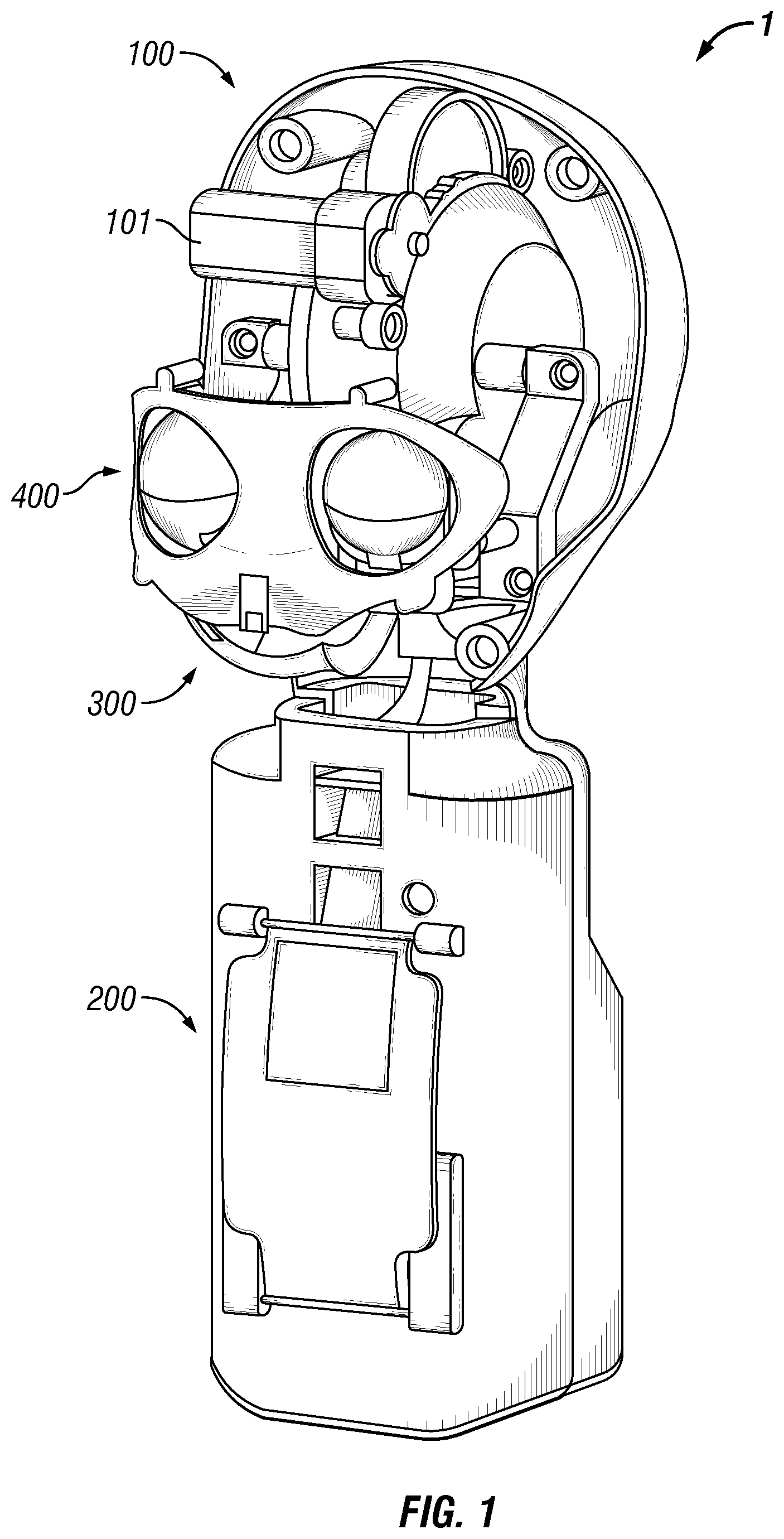
[0024] FIG. 1 shows an embodiment of an animatronic toy with an external appearance shell removed.
[0025] FIG. 2 shows an embodiment of a geneva gear pair comprised of a geneva driver and a geneva follower.
[0026] FIG. 3 shows an embodiment of a compound geneva gear assembly.
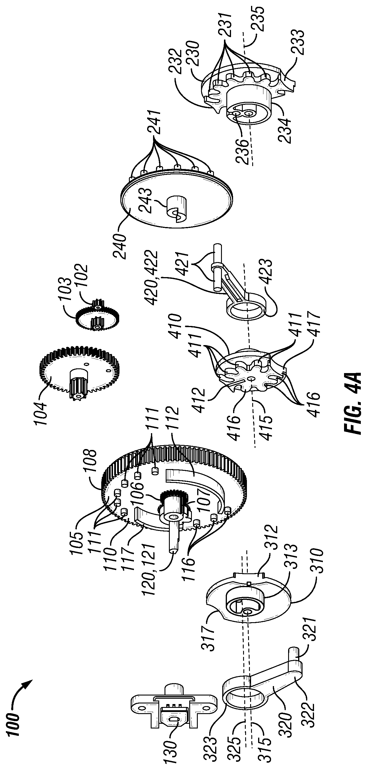
[0027] FIGS. 4A and 4B show exploded views of an embodiment of a drive mechanism.
[0028] FIGS. 5A and 5B show an embodiment of a breath assembly.
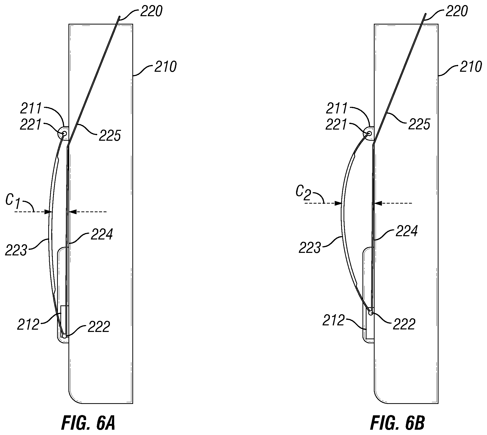
[0029] FIGS. 6A and 6B show an embodiment of a body and a breath plate of a breath assembly.
[0030] FIGS. 7A-7D show an embodiment of a geneva gear pair of the breath assembly of FIGS. 5A and 5B.
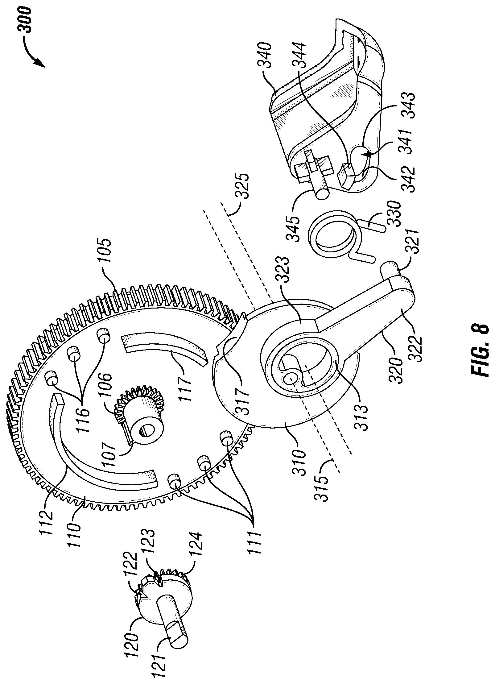
[0031] FIG. 8 shows a partially exploded view of an embodiment of a jaw assembly.
[0032] FIGS. 9A-9D show different positions of the jaw assembly embodiment of FIG. 8.
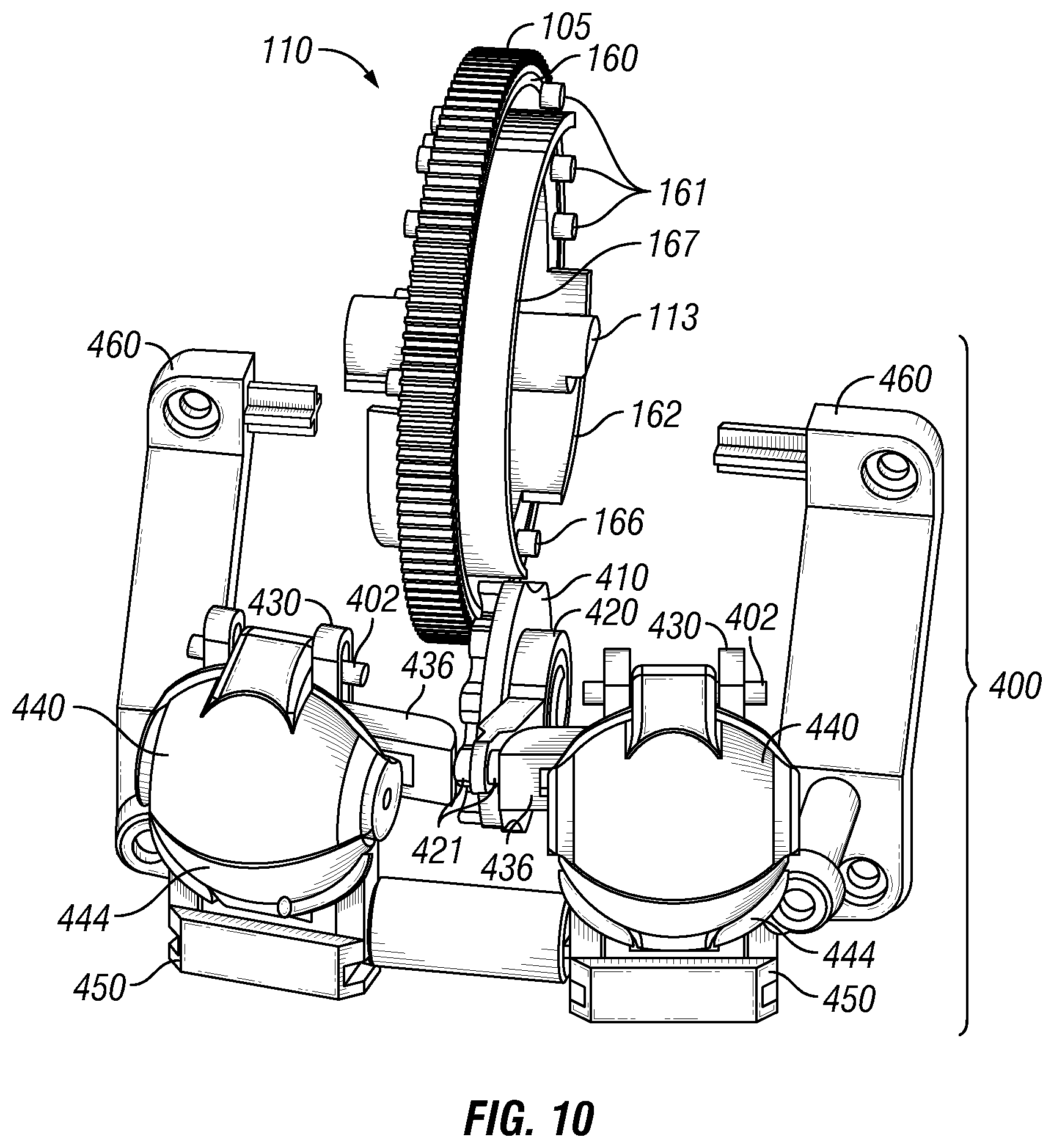
[0033] FIG. 10 shows an embodiment of an eye assembly.
[0034] FIG. 11 shows an exploded view of a portion of the eye assembly embodiment of FIG. 10.
[0035] FIGS. 12A-12D show various positions of the eye assembly embodiment of FIG. 10.
[0036] FIG. 13 shows a schematic diagram of an action wheel of an embodiment of a compound geneva gear assembly.
[0037] FIG. 14 shows a schematic diagram of an action wheel of an embodiment of a compound geneva gear assembly.
[0038] FIG. 15 shows an embodiment of an animatronic toy with an external appearance shell removed.
[0039] FIG. 16 shows an embodiment of an eye assembly.
[0040] FIG. 17 shows an embodiment of a jaw assembly.
[0041] FIGS. 18A and 18B show exploded views of an embodiment of a drive mechanism.
[0042] FIGS. 19A-19C show an embodiment of a geneva gear pair comprised of a geneva driver and a geneva follower in different positions.
[0043] FIGS. 20A and 20B show an embodiment of a geneva gear pair comprised of a geneva driver and a geneva follower in different positions.
[0044] FIGS. 21A and 21B show an embodiment of a geneva gear pair comprised of a geneva driver and a geneva follower in different positions.
[0045] FIG. 22 shows an exploded view of an embodiment of an eye assembly.
[0046] While the disclosure is susceptible to various modifications and alternative forms, specific embodiments have been shown by way of example in the drawings and will be described in detail herein. However, it should be understood that the disclosure is not intended to be limited to the particular forms disclosed. Rather, the intention is to cover all modifications, equivalents and alternatives falling within the scope of the disclosure as defined by the appended claims.
DETAILED DESCRIPTION
[0047] FIG. 1 shows an animatronic toy 1 without an external appearance shell. By way of example, an external appearance shell may be used to give the appearance of a human, an animal, a mythical creature, or combinations thereof. Size and weight constraints may be of particular importance in animatronic toys. Accordingly, it may be desirable to provide a drive assembly that is operable to control multiple features simultaneously. In addition, it may be desirable to provide a drive assembly that is compact to operate features within a confined area.
[0048] Animatronic toy 1 includes a drive mechanism 100 controlled by an electric motor 101. Drive mechanism 100 includes geneva gear pairs for controlling a plurality of moving parts of animatronic toy 1. As shown in FIG. 1, the moving parts of the animatronic may include a breath assembly 200, a jaw assembly 300, and an eye assembly 400, or combinations thereof. As would be appreciated by the discussion herein, a drive mechanism may be used to control other features of animatronic toy. For example, movement of arms, neck, cheeks, brows, lips, legs, eyebrows, and blinking may be controlled by the drive mechanism. A plurality of movements may be controlled by a single motor. Other examples of movement may include movement of eyes up/down or side-to-side, wrinkling a nose, or whipping or wagging a tail.
[0049] FIG. 2 shows an exemplary embodiment of a geneva gear pair 5 comprised of a geneva driver 10 and a geneva follower 20. For purposes of illustration, geneva follower 20 has been spatially separated from geneva driver 10, although geneva follower 20 would be positioned to driven by geneva driver 10 during operation. Geneva driver 10 is rotatable about an axis 15 and geneva follower 20 is rotatable about an axis 25. As geneva driver 10 rotates, a portion of geneva driver 10 engages a portion of geneva follower 20, thereby causing geneva follower 20 to rotate in the opposite direction of geneva driver 10.
[0050] A geneva driver includes at least one set of teeth and at least one stop. In some embodiments, a geneva driver includes a plurality of sets of teeth and a plurality of stops. The sets of teeth of the geneva driver are distributed in an arcuate pattern and the stops are arcuately positioned in an alternating pattern with the sets of teeth. A geneva follower includes at least one set of teeth and at least one cutout portion. In some embodiments, a geneva follower includes a plurality of sets of teeth and a plurality of cutouts. The sets of teeth of the geneva follower are distributed in an arcuate pattern and the cutouts are positioned in an alternating pattern with the sets of teeth. The number of sets of teeth of the geneva follower may correspond with the number of sets of teeth of the geneva driver and the number of stops of the geneva driver may correspond with the number of cutout portions of the geneva follower.
[0051] The relative positions of the geneva driver and the geneva follower for one or more angular spans of active rotation and one or more angular spans of passive rotation. During active rotation, one of the sets of teeth of the geneva driver mesh with one of the sets of teeth of the geneva follower, which causes the geneva follower to rotate with the geneva driver. The sets of teeth on the geneva follower may have a different radius (measured from the axis of rotation of geneva follower) than the sets of teeth on the geneva driver (measured from the axis of rotation of the geneva driver. As a result, the during a span of active rotation, the geneva follower may have a greater angular velocity than the geneva driver. For instance, a set of teeth of the geneva driver may cover a span of 60.degree. and the corresponding set of teeth of the geneva follower may cover a span of 200.degree..
[0052] During passive rotation, one of the cutouts of the geneva follower is positioned such that the geneva driver may continue rotating without causing rotational motion of the geneva follower. As the geneva driver rotates, one of the stops of the geneva driver is positioned adjacent to the cutout of the geneva follower. As a result, external forces that would cause geneva follower to rotate, such as a child moving an arm connected to the geneva follower, do not cause rotation of the geneva driver. In this manner, a geneva gear pair allows for continuous movement of a geneva driver while movement of the geneva follower is interruptible. It is further appreciated that in some embodiments, a "set of teeth" may include a single tooth.
[0053] As shown in FIG. 2, geneva driver 10 may include a set of perimeter teeth 18 to impart motion to geneva driver 10. Geneva driver 10 includes a plurality of sets of teeth including a first set of teeth 11 and a second set of teeth 16. Geneva driver 10 includes a plurality of stops including a first stop 12 and a second stop 17. The first set of teeth 11 is distributed in an arcuate pattern around an axis of rotation 15 from a first tooth 11A to a second tooth 11B, located at opposite ends of the first set of teeth 11. The second set of teeth 16 is distributed in an arcuate pattern from a first tooth 16A to a second tooth 16B, located at opposite ends of the second set of teeth 16. First stop 12 is arcuately positioned between second tooth 11B of the first set of teeth 11 and first tooth 16A of the second set of teeth 16. Second stop 17 is arcuately positioned between first tooth 11A of the first set of teeth 11 and second tooth 16B of the second set of teeth 16. As shown in FIG. 2, the first set of teeth 11 and the second set of teeth 16 are pegs extending from a face of geneva driver 10. The first set of teeth 11, the second set of teeth 16, the first stop 12 and the second stop 17 are coplanar.
[0054] Geneva follower 20 includes a plurality of sets of teeth including a first set of teeth 21 and a second set of teeth 26. Geneva follower 20 includes a plurality of cutouts including a first cutout 22 and a second cutout 27. The first set of teeth 21 is distributed in an arcuate pattern and the second set of teeth 26 is distributed in an arcuate pattern around an axis of rotation 25. For the purposes of clarity, the first set of teeth 21 and the second set of teeth 26 are located on the opposing side of geneva follower 20 and have therefore been shown in broken lines. As shown in FIG. 2, the first set of teeth 21 forms a first groove 21A and a second groove 21B at opposing ends of its arcuate pattern. The second set of teeth 26 forms a first groove 26A and a second groove 26B at opposing ends of its arcuate pattern. First cutout 22 is positioned between second groove 21B of the first set of teeth 21 and first groove 26A of the second set of teeth 26. Second cutout 27 is positioned between first groove 21A of the first set of teeth 21 and second groove 26B of the second set of teeth 26. The first set of teeth 21, the second set of teeth 26, the first cutout 22 and the second cutout 27 are coplanar.
[0055] The first set of teeth 11 of geneva driver 10 mesh with the first set of teeth 21 of geneva follower 20 and the second set of teeth 16 of geneva driver 10 mesh with the second set of teeth 26 of geneva follower 20. During operation, geneva driver 10 is rotated counterclockwise and the first set of teeth 11 of geneva driver 10 mesh with the first set of teeth 21 of geneva follower 20 causing geneva follower 20 to rotate until second tooth 11B is positioned in second groove 21B. Further rotation of geneva driver 10 causes second tooth 11B to rotate out of second groove 21B without further rotation of geneva follower 20. Further rotation of geneva driver 10 causes first stop 12 to pass adjacent to first cutout 22 without rotating geneva follower 20. First stop 12 prevents external forces acting upon geneva follower 20, such as attempting to move an attached limb, from causing misalignment between geneva follower 20 and geneva driver 10. Further rotation of geneva driver 10 causes first tooth 16A of the second set of teeth 16 to enter first groove 26A of geneva follower 20, upon which further rotation of geneva driver 10 is imparted to geneva follower 20 via the second set of teeth 16 until second tooth 16B is positioned in second groove 26B. Further rotation of geneva driver 10 causes second tooth 16B to rotate out of second groove 26B without further rotation of geneva follower 20. Further rotation of geneva driver 10 causes second stop 17 to pass adjacent to second cutout 27 without rotating geneva follower 20.
[0056] Due to the configuration of the geneva gear pair, geneva driver 10 and geneva follower 20 both complete a rotation of 360.degree.. However, the rotation of geneva follower 20 is interrupted as the stops of geneva driver 10 pass adjacent to the cutouts of geneva follower 20. During the active period where the sets of teeth of geneva driver 10 and geneva follower 20 are intermeshed, and rotation is imparted to geneva follower 20, the angular velocity of geneva follower 20 is greater than geneva driver 10. Geneva driver 10 may be rotated clockwise or counterclockwise to simulate different movements.
[0057] FIG. 3 shows an embodiment of a compound geneva gear assembly 40. Compound geneva gear assembly 40 includes a drive gear 50, a plurality of geneva drivers and a plurality of geneva followers. Drive gear 50 receives rotational energy, such as from an electric motor 101 (shown in FIG. 1) and imparts rotational motion into the plurality of geneva drivers. By way of example, drive gear 50 may receive rotation energy via another gear meshed with drive gear 50 or by a drive shaft (not shown in FIG. 3).
[0058] The geneva followers are each positioned to be driven by a corresponding geneva driver and form geneva gear pairs. The plurality of geneva drivers are rotationally coupled to each other, such that rotation imparted to one geneva driver is imparted to the other geneva drivers. In some embodiments, the geneva drivers are rigidly rotationally coupled so that they rotate at a common angular velocity. In some embodiments, the geneva drivers may be coupled via a gear reduction, such as by a planetary gearing assembly, so that the geneva drivers rotate simultaneously but at least one of the geneva drivers has a different angular velocity from another geneva driver. In other embodiments, a geneva driver may travel through a range of motion before rotation of another geneva driver is engaged. In some embodiments, a geneva driver may be rotationally coupled in a first direction of rotation, but not in another direction of rotation.
[0059] The plurality of geneva drivers of compound geneva gear assembly 40 includes a first geneva driver 51, a second geneva driver 52, a third geneva driver 55A, a fourth geneva driver 55B, a fifth geneva driver 56, or subsets or combinations thereof. As shown in FIG. 3, drive gear 50 has a first side and a second side opposite the first side. First geneva driver 51, third geneva driver 55A, and fourth geneva driver 55B are positioned on the first side of drive gear 50. Second geneva driver 52 and fifth geneva driver 56 are positioned on the second side of drive gear 50.
[0060] Drive gear 50, first geneva driver 51, and second geneva driver 52 may be rigidly connected, such as a single integral piece, to form a compound geneva driver. A compound geneva driver includes a plurality of rotationally coupled geneva drivers that are not coplanar. As first geneva driver 51 rotates, second geneva driver 52 rotates in unison. Third geneva driver 55A and fourth geneva driver 55B are rotationally coupled to first geneva driver 51 via a first extension shaft 53. Second geneva driver 52 is rotational coupled to fifth geneva driver 56 via a second extension shaft 54. Third geneva driver 55A and fourth geneva driver 55B may be a compound geneva driver 55 with third geneva driver 55A and fourth geneva driver 55B positioned on opposing sides.
[0061] The plurality of geneva followers are positioned to be driven by one of the plurality of geneva drivers. As shown in FIG. 3, a first geneva follower 61 is positioned to be driven by first geneva driver 51, two second geneva followers 62 are positioned to be driven by second geneva driver 52, a third geneva follower 65A is positioned to be driven by third geneva driver 55A, a fourth geneva follower 65B is positioned to be driven by the fourth geneva drier 55B, and a plurality of fifth geneva followers 66, such as more than two, are positioned to be driven by fifth geneva driver 56. In some embodiments, first extension shaft 53 and/or second extension shaft 54 may be rotationally coupled to more than two geneva drivers or additional extensions may be used.
[0062] One or more of the plurality of geneva followers may be rotationally coupled to an additional geneva driver to form a nested geneva gear pair. In a nested geneva gear pair, a first layer includes a geneva driver and a geneva follower and a second layer includes another geneva follower and a geneva driver rotationally coupled to the geneva driver of the first layer. The geneva gear pair of the first layer allows for continuous movement of the geneva driver of the first layer while movement of the geneva follower of the first layer is interruptible. The geneva follower of the second layer is interruptible from the geneva driver of the second layer, which is rotationally coupled to the geneva driver of the first layer. As shown in FIG. 3, a sixth geneva driver 59 is rotationally coupled to third geneva follower 65A via a third extension shaft 57 and a sixth geneva follower 69 driven by sixth geneva driver 59. By way of example, a nested geneva gear pair may be further utilized to link movements. Third geneva follower 65A may control eye movement and sixth geneva follower 69 may control movement of eyebrows, such that the movement of eyebrows is controlled by positioned of the eyes.
[0063] Drive gear 50 distributes power into a plurality of drive paths. As shown in FIG. 3, compound geneva gear assembly 40 includes drive paths through nine geneva followers. Rotation is imparted to first geneva driver 51 by drive gear 50, which imparts rotation to first geneva follower 61 and to compound geneva driver 55 via first extension shaft 53. Rotation of compound geneva driver 55 imparts rotation to third geneva follower 65A through third geneva driver 55A and to fourth geneva follower 65B through fourth geneva driver 55B. Rotation of third geneva follower 65A imparts rotation to sixth geneva driver 59, which imparts rotation to sixth geneva follower 69. Rotation is also imparted from drive gear 50 to second geneva driver 52, which imparts rotation to second geneva followers 62 and to fifth geneva driver 56 via second extension shaft 54. Rotation of fifth geneva driver 56 imparts rotation to the plurality of fifth geneva followers 66. As may be appreciated from the discussion herein, rotation between geneva gear pairs is interruptible.
[0064] FIGS. 4A and 4B show exploded views of an embodiment of a drive mechanism 100. Drive mechanism 100 includes an electric motor 101 (shown in FIG. 1), a drive gear 102 coupled to electric motor 101, and a compound geneva driver 105. Drive mechanism 100 may include one or more, such as a plurality, of reduction gears 103, 104. Compound geneva driver 105 is driven by electric motor 101. Compound geneva driver 105 may include a set of perimeter teeth 108 for engaging a gear train including reduction gears 103, 104 connected to electric motor 101.
[0065] Drive mechanism 100 may include a through hole potentiometer 130 for measuring angular position of compound geneva driver 105. Compound geneva driver 105 may include indexing teeth 106 and an indexing stop 107 positioned on a face of compound geneva driver 105. Drive mechanism 100 may include an indexing gear 120 having a shaft 121 to be received within through hole potentiometer 130 and a support sleeve 131. As shown in FIG. 8, indexing gear 120 includes indexing teeth 124 and a first indexing recess 122 circumferentially separated from a second indexing recess 123. Indexing teeth 124 of indexing gear 120 mesh with indexing teeth 106 of compound geneva driver 105. Depending upon the angular position of indexing stop 107 of compound geneva driver 105, indexing stop 107 may be received into either first indexing recess 122 or second indexing recess 123 of indexing gear 120 and prevent further rotation thereof.
[0066] Referring again to FIGS. 4A and 4B, compound geneva driver 105 includes a first geneva driver 110 on a first side and a second geneva driver 160 on a second side, the second side opposite than the first side. First geneva driver 110 and second geneva driver 160 are positioned in parallel planes. First geneva driver 110 includes a plurality of sets of teeth including a first set of teeth 111 and a second set of teeth 116. First geneva driver 110 includes a plurality of stops including a first stop 112 and a second stop 117. The first set of teeth 111 and the second set of teeth 116 are each distributed in an arcuate pattern. First stop 112 is arcuately positioned between the first set of teeth 111 and the second set of teeth 116. Second stop 117 is arcuately positioned between the second set of teeth 116 and the first set of teeth 111.
[0067] Second geneva driver 160 includes a plurality of sets of teeth including a first set of teeth 161 and a second set of teeth 166. Second geneva driver 160 includes a plurality of stops including a first stop 162 and a second stop 167. The first set of teeth 161 and the second set of teeth 166 are each distributed in an arcuate pattern. First stop 162 is arcuately positioned between the first set of teeth 161 and the second set of teeth 166. Second stop 167 is arcuately positioned between the second set of teeth 166 and the first set of teeth 161.
[0068] Compound geneva driver 105 includes a driver extension 113. Third geneva driver 240 includes a set of teeth 241 and a stop 242. The set of teeth 241 is distributed in an arcuate patter with stop 242 arcuately positioned between ends of the set of teeth 241. Third geneva driver 240 includes a driver extension 243 configured to rotationally couple with driver extension 113 of compound geneva driver 105. Driver extension 113 of compound geneva driver 105 may be rigidly rotationally coupled with driver extension 243 of third geneva driver 240. The connection between second geneva driver 160 and third geneva driver 240 may be formed of complementary shapes to form a rigid connection. In some embodiments, the shapes may be partially complementary. For example, driver extension 113 may form a first circular sector and driver extension 243 may form a second circular sector, with the sum of the first circular sector and the second circular sector being less than 360.degree.. Second geneva driver 160 may rotate through the incomplete circular sector before driver extension 113 of second geneva driver 160 contacts driver extension 243 of third geneva driver 240 and imparts rotational motion to third geneva driver 240. In other embodiments, a ramped profile, such as a ratcheting freewheel, may be used to permit a rigid connection with driver extension 243 of third geneva driver 240 when rotated in a driven direction, but allow uncoupled rotation of second geneva driver 160 in an opposite direction.
[0069] Drive mechanism 100 includes a first geneva follower 310, a second geneva follower 410, and a third geneva follower 230. Drive mechanism 100 forms a plurality of drive paths for controlling moving parts of an animatronic toy 1 (shown in FIG. 1). Power supplied by electric motor 101 is transferred through drive gear 102, reduction gears 103, 104, and is supplied to compound geneva driver 105 via perimeter teeth 108. As shown in FIGS. 4A and 4B, power from electric motor 101 is distributed into three drive paths. Compound geneva driver 105 and first geneva driver 110 impart rotational motion to first geneva follower 310. Compound geneva driver 105 and second geneva driver 160 impart rotational motion to second geneva follower 410. Compound geneva driver 105 and driver extension 113 impart rotational motion to driver extension 243 of third geneva driver 240, which imparts rotational motion to third geneva follower 230.
[0070] First geneva follower 310 includes a plurality of sets of teeth including a first set of teeth 311 and a second set of teeth 316. First geneva follower 310 includes a plurality of cutouts including a first cutout 312 and a second cutout 317. The first set of teeth 311 is distributed in an arcuate pattern and the second set of teeth 316 is distributed in an arcuate pattern. First cutout 312 and second cutout 317 are position at ends of the first set of teeth 311 and separate the first set of teeth 311 from the second set of teeth 316. First cutout 312 and second cutout 317 may be angularly offset by less than 180.degree.. First geneva follower 310 includes a protrusion 313 configured to receive a portion of a moving feature for rotational motion about protrusion 313. Protrusion 313 is eccentric to an axis of rotation 315 of first geneva follower 310. Protrusion 313 may be positioned on an opposite side of first geneva follower 310 from the set of teeth 311.
[0071] Protrusion 313 is configured to receive and rotatably support a crank 320. Crank 320 includes a crank arm 322, a crank pin 321 at a first end of crank arm 322, and a crank ring 323 at a second end of crank arm 322. Crank 320 includes an axis of rotation 325 that is offset from the axis of rotation 315 of first geneva follower 310. Crank ring 323 of crank 320 and protrusion 313 of first geneva follower 310 may be formed of other shapes, such as a slot and pin. In some embodiments, a ring-shape protrusion 313 may be used to increase the offset from the axis of rotation to increase the "throw" of crank 320.
[0072] Second geneva follower 410 includes a plurality of sets of teeth including a first set of teeth 411 and a second set of teeth 416. Second geneva follower 410 includes a plurality of cutouts including a first cutout 412 and a second cutout 417. The first set of teeth 411 is distributed in an arcuate pattern and the second set of teeth 416 is distributed in an arcuate pattern. First cutout 412 and second cutout 417 are position at ends of the first set of teeth 411 and separate the first set of teeth 411 from the second set of teeth 416. First cutout 412 and second cutout 417 may be angularly offset by exactly 180.degree.. Second geneva follower 410 includes a protrusion 413 configured to receive a portion of a moving feature for rotational motion about protrusion 413. Protrusion 413 is eccentric to an axis of rotation 415 of second geneva follower 410. Protrusion 413 may be positioned on the opposite side of second geneva follower 410 from the set of teeth 411.
[0073] Protrusion 413 is configured to receive and rotatably support a crank 420. Crank 420 includes a crank arm 422, a crank pin 421 at a first end of crank arm 422, and a crank ring 423 at a second end of crank arm 422. Crank 420 includes an axis of rotation 425 that is offset from the axis of rotation 415 of second geneva follower 410. Crank ring 423 of crank 420 and protrusion 413 of second geneva follower 410 may be formed of other shapes, such as a slot and pin. In some embodiments, a ring-shape protrusion 413 may be used to increase the offset from the axis of rotation to increase the "throw" of crank 420.
[0074] Third geneva follower 230 includes a set of teeth 231, a first cutout 232, and a second cutout 233, with the set of teeth 231 distributed in an arcuate pattern from first cutout 232 to second cutout 233. Set of teeth 231 of third geneva follower 230 are configured to mesh with the set of teeth 241 of third geneva driver 240. Third geneva follower 230 includes a protrusion 234 extending from a face of third geneva follower 230 and an axis of rotation 235. Protrusion 234 is configured to receive a portion of a moving feature. Protrusion 234 may be cylindrical. Protrusion 234 includes a recess 236. Protrusion 234 may be coaxial with axis of rotation 235. Protrusion 234 may be positioned on the same side of third geneva follower 230 as the set of teeth 231.
[0075] FIGS. 5A and 5B show an embodiment of a breath assembly 200. Breath assembly 200 includes a body 210 and a breath plate 220. Breath assembly 200 includes third geneva driver 240 and third geneva follower 230 of drive mechanism 100 (best shown in FIGS. 4A and 4B). The set of teeth 241 of third geneva driver 240 mesh the with the set of teeth 231 of third geneva follower 230.
[0076] Body 210 provides a frame to a chest of an animatronic toy 1 (shown in FIG. 1). Body 210 includes a set of upper holes 211, a set of lower slots 212, and a guide 215. Breath plate 220 includes a first set of pins 221, a second set of pins 222, a chest portion 223 between the first set of pins 221 and the second set of pins 222, a connector 226, and a flexible portion 224 connecting the connector 226 to the second set of pins 222. Flexible portion 224 may pass through guide 215 of body 210. Connector 226 is shaped to be retained by recess 236 of protrusion 234 of third geneva follower 230. By way of example, connector 226 may be a pin that is received within recess 236. Flexible portion 224 is sufficiently pliant to be coiled around protrusion 234 of third geneva follower 230 as it rotates. Another portion 225 may be less pliant than flexible portion 224 and connect to the second set of pins 222. The first set of pins 221 of breath plate 220 are rotatably disposed within upper holes 211 of body 210. The second set of pins 222 of breath plate 220 are slidably disposed within lower slots 212 of body 210.
[0077] Rotation of third geneva follower 230 causes movement of breath plate 220 to simulate a breath. FIGS. 6A and 6B show a side view of body 210 and breath plate 220. The first set of pins 221 of breath plate 220 are rotatably disposed within upper holes 211 of body 210 and second set of pins 222 of breath plate 220 are slidably disposed within lower slots 212 of body 210. In FIG. 6A, the second set of pins 222 of breath plate 220 are positioned at the bottom of lower slots 212 and flexible portion 224 is fully extended. Chest portion 223 has a flattened profile that extends from first set of pins 221 to second set of pins 222 with a distance c.sub.1 between chest portion 223 and body 210. In FIG. 6B, first set of pins 221 of breath plate 220 have rotated within upper holes 211 of body 210 and second set of pins 222 of breath plate 220 have moved to an upper portion of lower slots 212. Portion 225 may slide within guide 215 (shown in FIG. 5B) to reduce abrasion upon flexible portion 225. Chest portion 223 has an expanded profile that extends from first set of pins 221 to second set of pins 222 with a distance c.sub.2 between chest portion 223 and body 210, distance c.sub.2 being greater than distance c.sub.1.
[0078] FIGS. 7A-7D show positions of third geneva driver 240 and third geneva follower 230 through the range of motion of breath assembly 200. Connector 226 of breath plate 220 is retained within recess 236 of protrusion 234 of third geneva follower 230. The set of teeth 241 of third geneva driver 240 are distributed in an arcuate pattern from a first tooth 241A to a second tooth 241B, located at opposite ends of the set of teeth 241. For the purposes of clarity, the set of teeth 241 is located on the opposing side of third geneva follower 230 and have therefore been shown in broken lines. FIG. 7A shows third geneva driver 240 and third geneva follower 230 in a first relative position corresponding to the flatted profile shown in FIG. 6A. Second tooth 241B is adjacent to first cutout 232 and a portion of stop 242 of third geneva driver 240 is adjacent to first cutout 232.
[0079] Third geneva driver 240 continues counter-clockwise rotation through the span of stop 242 without rotating third geneva follower 230 until first tooth 241A is adjacent to first cutout 232 as shown in FIG. 7B. During this rotation, other geneva drivers, such as first geneva driver 110 and second geneva driver 160 (shown in FIGS. 8A and 8B) may engage their corresponding geneva followers. In this position, breath plate 220 remains in the flatted profile. Further rotation of third geneva driver 240 causes first tooth 241A to contact the teeth 231 of third geneva follower 230, upon which further rotation of third geneva driver 240 is imparted to third geneva follower 230 until second tooth 241B is positioned adjacent to second cutout 237 and a portion of stop 242 of third geneva driver 240 is adjacent to second cutout 237 as shown in FIG. 7C. As third geneva follower 230 rotates, flexible portion 224 of breath plate 220 is coiled around protrusion 234 of third geneva follower 230. As flexible portion 224 and connected portion 225 of breath plate 220 is coiled around protrusion 234 of third geneva follower 230, second set of pins 222 (shown in FIG. 6B) slide upward within lower slots 212 of body 210 of breath assembly 200. The upward movement of second set of pins 222 causes chest portion 223 to bow outward from body 210 and pivot first set of pins 221 within upper holes 211 to give the appearance of breathing. Referring again to FIG. 7C, third geneva driver 240 may continue counter-clockwise rotation through the span of stop 242 without rotating third geneva follower 230 until first tooth 241A is again adjacent to first cutout 232 as shown in FIG. 7D. During this rotation, other geneva drivers, such as first geneva driver 110 and second geneva driver 160 (shown in FIGS. 8A and 8B) may engage their corresponding geneva followers.
[0080] FIG. 8 shows a partially exploded view of an embodiment of a jaw assembly 300. Jaw assembly 300 includes a jaw 340 and a torsion spring 330. Jaw assembly 300 includes first geneva driver 110 of compound geneva driver 105, first geneva follower 310, and crank 320 of drive mechanism 100 (shown in FIGS. 4A and 4B). Jaw assembly 300 controls movement of a mouth of animatronic toy 1 (shown in FIG. 1).
[0081] Jaw 340 is configured to rotate about an axis of rotation 345, such as by a pinned connection, to simulate a mouth opening and closing. Crank pin 321 is connected to jaw 340 at a position offset from axis of rotation 345. Jaw 340 includes an arcuate slot 341 extending from a first end 342 to a second end 343. Arcuate slot 341 may have a constant radius of curvature from axis of rotation 345. Jaw also includes a stop 344. Crank 320 includes a crank arm 322, a crank pin 321 at a first end of crank arm 322, and a crank ring 323 at a second end of crank arm 322. Crank ring 323 of crank 320 is rotatably supported upon protrusion 313 of first geneva follower 310 and crank pin 321 is received within arcuate slot 341 of jaw 340. Torsion spring 330 is positioned between stop 344 and crank pin 321 to bias crank pin 321 within arcuate slot 341. Torsion spring 330 may also permit movement of crank pin 321 with arcuate slot 341 due to external forces, such as to prevent damage by a child playing with the mouth of an animatronic toy or to avoid jaw 340 from clamping upon a finger. As first geneva follower 310 rotates about axis of rotation 315, protrusion 313 is moved in an orbital motion around axis of rotation 315 and causes crank ring 323 upon protrusion 313 to rotate about axis of rotation 325 as it orbits around axis of rotation 315. The diameter of orbital path of the axis of rotation 325 of crank 320 is the "throw" of crank 320. The diameter of protrusion 313 may be increased and/or protrusion 313 may be further offset from axis of rotation 315 to increase the throw of crank 320.
[0082] FIGS. 9A-9D show positions of first geneva driver 110 and first geneva follower 310 through a range of motion of jaw assembly 300. The first set of teeth 111 of first geneva driver 110 are distributed in an arcuate pattern from a first tooth 111A to a second tooth 111B, located at opposite ends of the first set of teeth 111, and the second set of teeth 116 of first geneva driver 110 are distributed in an arcuate pattern from a first tooth 116A to a second tooth 116B, located at opposite ends of the second set of teeth 116. First stop 112 is arcuately positioned between second tooth 111B of the first set of teeth 111 and the first tooth 116A of the second set of teeth 116. Second stop 117 is arcuately positioned between first tooth 111A of the first set of teeth 111 and second tooth 116B of the second set of teeth 116. For the purposes of clarity, the first set of teeth 311 and second set of teeth 316 are located on the opposing side of first geneva follower 310 and have therefore been shown in broken lines. FIG. 9A shows first geneva driver 110 and first geneva follower 310 in a first relative position corresponding to a mouth closed position. The first set of teeth 311 of first geneva follower 310 are engaged with the first set of teeth 111 of first geneva driver 110. Indexing stop 107 is positioned within first indexing recess 122 of indexing gear 120 and the position is determined by through hole potentiometer 130 (shown in FIGS. 4A and 4B). In the first relative position, axis of rotation 325 of crank 320 and the axis of rotation 345 of jaw 340 are separated by a vertical distance of h.sub.1 and a horizontal distance d.sub.1.
[0083] First geneva driver 110 rotates in a clockwise direction and first geneva follower 310 rotates in a counter-clockwise direction as the first set of teeth 111 of first geneva driver 110 contact the first set of teeth 311 of first geneva follower 310. First geneva follower 310 continues counter-clockwise rotation until first tooth 111A of the first set of teeth 111 of first geneva driver 110 moves out of contact with the first set of teeth 311 of first geneva follower 310 and second stop 117 is adjacent to second cutout 317 of first geneva follower 310. First geneva driver 110 continues clockwise rotation through the span of second stop 117 without rotating first geneva follower 310 until second tooth 116B of the second set of teeth 116 of first geneva driver 110 is adjacent to the second set of teeth 316 of first geneva follower 310 as shown in FIG. 9B. In this position, axis of rotation 325 of crank 320 and the axis of rotation 345 are separated by a vertical distance of h.sub.2 and a horizontal distance d.sub.2.
[0084] Further clockwise rotation of first geneva driver 110 causes second tooth 116B of the second set of teeth 116 of first geneva driver 110 to contact first geneva follower 310, upon which further rotation of first geneva follower 310 is imparted via the connections between the second set of teeth 116 of first geneva driver 110 and the second set of teeth 316 of first geneva follower 310 until first tooth 116A of the second set of teeth 116 of first geneva driver 110 is adjacent to first cutout 312 and a portion of first stop 112 of first geneva driver 110 is adjacent to first cutout 312 as shown in FIG. 9C. In this position, axis of rotation 325 of crank 320 and the axis of rotation 345 are separated by a vertical distance of h.sub.3 and a horizontal distance d.sub.3.
[0085] First geneva driver 110 may continue counter-clockwise rotation through the span of first stop 112 without rotating first geneva follower 310 until second tooth 111B of the first set of teeth 111 of first geneva driver 110 is again adjacent to first cutout 312. Further rotation of first geneva driver 110 will impart rotation to first geneva follower 310 via the connection between the first set of teeth 111 of first geneva driver 110 and the first set of teeth 311 of first geneva follower 310. As first geneva driver 110 rotates indexing teeth 106 mesh with indexing teeth 124 (shown in FIG. 8) of indexing gear 120 and causes rotation. Rotation of first geneva driver 110 in either direction occurs until indexing stop 107 is received into either first indexing recess 122 (shown in FIG. 9D) or second indexing recess 123 of indexing gear 120 (shown in FIG. 9A). In the final position, axis of rotation 325 of crank 320 and the axis of rotation 345 are separated by a vertical distance of h.sub.4 and a horizontal distance d.sub.4, which may be equal to distance h.sub.1 and distance d.sub.1, respectively.
[0086] The separation between axis of rotation 325 of crank 320 and the axis of rotation 345 affects the angular position of jaw 340 as crank pin 321 within arcuate slot 341 of jaw 340 moves with crank 320. As the separation changes, the position of crank pin 321 within arcuate slot 341 changes. As crank pin 321 is pulled toward first end 342 (shown in FIG. 8) of arcuate slot 341, jaw 340 pivots about its axis of rotation 345 to simulate a mouth opening. The configuration of the first set of teeth 311 and the second set of teeth 316 of first geneva follower 310 may be selected to determine how quickly the mouth opens and closes. In addition, second geneva driver 160 may be driven in alternating directions to simulate movements, such as chewing or talking.
[0087] FIG. 10 shows an embodiment of an eye assembly 400. Eye assembly 400 includes one or more eyelid frames 430, one or more eye frames 450, and supports 460. Eye assembly 400 includes one or more eyelids, such as an upper eyelid 440 and/or a lower eyelid 444 for each eyelid frame 430. As used herein, the terms "upper" and "lower" are used as relative to each other and could also refer to other opposite arrangements, such as side-to-side eyelids. As shown in FIG. 10, eye assembly 400 includes two eyelid frames 430, two upper eyelids 440, and two lower eyelids 444. In some embodiments, more than two eyelid frames 430 may be used for animatronic toys having more than two eyeballs. Eye assembly 400 includes second geneva driver 160 of compound geneva driver 105, second geneva follower 410, and crank 420 of drive mechanism 100 (shown in FIGS. 4A and 4B). Eye assembly 400 controls movement of eyes of animatronic toy 1 (shown in FIG. 1). Eyelid frame 430 is pivotally connected to eye frame 450 and eyelid frame 430 is pivotally connected to crank 420. Upper eyelid 440 and lower eyelid 444 are pivotally connected to eye frame 450 and slidably connected to eyelid frame 430.
[0088] For the purposes of illustration, FIG. 11 shows an exploded view of eye assembly 400 for only one eye. Support 460 provides for attachment of eye frame 450 to the head of an animatronic toy 1 (shown in FIG. 1). Eye frame 450 supports an eyeball 452 that is at least partially enclosed by upper eyelid 440 and/or lower eyelid 444. Eyeball 452 is selectively exposed by operation of upper eyelid 440 and/or lower eyelid 444. Eye frame 450 includes a hole 451 and an eyelid hole 455. Eyelid frame 430 is connected to crank pin 421 of crank 420 at a position offset from an axis of rotation of eyelid frame 430. Eyelid frame 430 may include a hole 431, a first slot 432, a second slot 433, a recess 435, and a crank hole 436. First slot 432 provides a slidable connection for upper eyelid 440 and second slot 433 provides a slidable connection for lower eyelid 444. First slot 432 may be longer than second slot 433 since upper eyelid 440 has further angular movement. Crank hole 436 is shaped to receive crank pin 421 of crank 420. Crank 420 may include a plurality of crank pins 421 for controlling a plurality of eyelid frames 430. Hole 431 of eyelid frame 430 is aligned with hole 451 of eye frame 450. A pin 401 may be received through hole 431 of eyelid frame 430 and hole 451 of eye frame 450 to pivotally support eyelid frame 430 upon eye frame 450.
[0089] Upper eyelid 440 includes an eyelid hole 442 and lower eyelid 444 includes an eyelid hole 443. Upper eyelid 440 and lower eyelid 444 may include a hole 445 aligned with eyelid hole 455 of eye frame 450. A pin 405 may be received through hole 445 of upper eyelid 440 and lower eyelid 444 and through eyelid hole 455 of eye frame 450 to pivotally support upper eyelid 440 and lower eyelid 444 upon eye frame 450.
[0090] A portion of upper eyelid 440 is slidably disposed within first slot 432 of eyelid frame 430. A portion of lower eyelid 444 is slidably disposed within second slot 433 of eyelid frame 430. A first pin 402 may be received through eyelid hole 442 of upper eyelid and first slot 432. A second pin 403 may be received through eyelid hole 443 of lower eyelid 444 and second slot 433.
[0091] Crank ring 423 at the second end of crank arm 422 of crank 420 is rotatably supported upon protrusion 413 of second geneva follower 410 and crank pin 421 at the first end of crank arm 422 is received within crank hole 436 of eyelid frame 430. As second geneva follower 410 rotates about axis of rotation 415, protrusion 413 is moved in an orbital motion around about axis of rotation 415 and causes crank ring 423 upon protrusion 413 to rotate about axis of rotation 425 as it orbits around axis of rotation 415. The diameter of orbital path of the axis of rotation 425 of crank 420 is the throw of crank 420. The diameter of protrusion 413 may be increased and/or protrusion 413 may be further offset from axis of rotation 415 to increase the throw of crank 420.
[0092] FIGS. 12A-12D show positions of second geneva driver 160 and second geneva follower 410 through the range of motion of eye assembly 400. The first set of teeth 161 is distributed in an arcuate pattern from a first tooth 161A to a second tooth 161B, located at opposite ends of the first set of teeth 161. The second set of teeth 166 is distributed in an arcuate pattern from a first tooth 166A to a second tooth 166B, located at opposite ends of the second set of teeth 166. First stop 162 is arcuately positioned between second tooth 161B of the first set of teeth 161 and first tooth 166A of the second set of teeth 166. Second stop 167 is arcuately positioned between first tooth 161A of the first set of teeth 161 and second tooth 166B of the second set of teeth 166.
[0093] FIG. 12A shows second geneva driver 160 and second geneva follower 410 in a first relative position corresponding to an eyes-open position. In this position, the angle of separation .theta..sub.1 between eye frame 450 and the first slot 432 and second slot 433 of eyelid frame 430 and is great enough to give the appearance of open eyes. First tooth 161A is adjacent to first cutout 412 and a portion of second stop 167 of second geneva driver 160 is adjacent to first cutout 412. Counter-clockwise rotation of second geneva driver 160 causes first tooth 161A of the first set of teeth 161 to contact second geneva follower 410 and further rotation imparts clockwise rotation to second geneva follower 410 via the connection between the first set of teeth 161 of second geneva driver 160 and the first set of teeth 411 of second geneva follower 410 until second tooth 161B of the first set of teeth 161 of second geneva driver 160 is adjacent to second cutout 417 and a portion of first stop 162 of second geneva driver 160 is adjacent to second cutout 417 as shown in FIG. 12B. In this position, the angle of separation .theta..sub.2 between eyelid frame 430 and eye frame 450 is low, such as zero, or at least lower than angle of separation .theta..sub.1 to give the appearance of closed eyes.
[0094] Second geneva driver 160 continues counter-clockwise rotation through the span of first stop 162 without rotating second geneva follower 410 until first tooth 166A of the second set of teeth 166 is adjacent to second cutout 417 as shown in FIG. 12C. As second geneva follower 410 has not rotated, the position of crank 420 remains stationary and the angle of separation 02 between eyelid frame 430 and eye frame 450 is maintained.
[0095] Further rotation of first geneva driver 110 causes first tooth 166A of the first set of teeth 166 of second geneva driver 160 to contact second geneva follower 410, upon which further rotation of contact second geneva follower 410 is imparted via the connection between the second set of teeth 166 of second geneva driver 160 and the second set of teeth 416 of second geneva follower 410 until second tooth 166B of the second set of teeth 116 of second geneva driver 160 is adjacent to first cutout 412 and a portion of second stop 167 of second geneva driver 160 is adjacent to first cutout 412 as shown in FIG. 12D. Second geneva driver 160 may continue counter-clockwise rotation through the span of second stop 167 without rotating second geneva follower 410 until first tooth 161A of the first set of teeth 161 is adjacent to first cutout 412 as shown in FIG. 12A.
[0096] The separation between axis of rotation 425 of crank 420 and the axis of rotation of eyelid frame 430 affects the angular position of upper eyelid 440 and lower eyelid 444 as crank pin 421 within crank hole 436 (shown in FIG. 11) causes eyelid frame 430 to pivot about pin 401. The configuration of the first set of teeth 411 and the second set of teeth 416 of second geneva follower 410 may be selected to determine how quickly the eyelids open and close, such as to simulate grogginess or blinking. In addition, second geneva driver 160 may be driven in alternating directions to simulate movements, such as blinking.
[0097] FIG. 13 shows a schematic diagram of an action wheel 500 of a compound geneva gear assembly. Action wheel 500 includes a first action 510, a second action 520, a third action 530, a fourth action 540, a fifth action 550, a sixth axis 560, a seventh action 570, and an eighth action 580. For the purposes of illustration, eight actions have been shown, but more or less actions can be used. Action wheel 500 demonstrates a range of motion for a compound geneva driver of a compound geneva gear assembly. The compound geneva driver includes a plurality of geneva drivers that are engaged with corresponding geneva followers depending on the angular position of the geneva drivers. As the compound geneva driver rotates through the 360.degree. range, the plurality of geneva drivers engage their corresponding geneva followers and cause actions 510-580. In some embodiments, a geneva driver may include a single geneva driver portion that engages a geneva follower. For example, third geneva driver 240 (shown in FIGS. 5A and 5B) shows a geneva driver having a single geneva driver portion (set of teeth 241) that engages a geneva follower. In some embodiments, a geneva driver may include multiple geneva driver portions that engage a single geneva follower. For example, second geneva driver 160 (shown in FIG. 11) includes multiple geneva driver portions (first set of teeth 161 and second set of teeth 166) that sequential engages a geneva follower to create two separate actions--eyes opening and eyes closing. In some embodiments, a geneva driver portion of a geneva driver may sequential engage multiple geneva followers. For example, second geneva driver 52 (shown in FIG. 3) may include a geneva driver portion that engages one of the two second geneva followers 62 at one angular position and engages the other of the two second geneva followers 62 at another angular position. As shown in FIG. 13, the actions occur in a discrete sequence, without overlap. However, in some embodiments, actions may overlap with each other.
[0098] FIG. 14 shows a schematic diagram of an action wheel 600 of a compound geneva gear assembly with overlapping actions. The action wheel 600 comprises a first ring 610 representing the angular position of a first geneva driver, a second ring 620 representing the angular position of a second geneva driver, and a third ring 630 representing the angular position of a third geneva driver. An action 611 occurs during an angular span in first ring 610. An action 621 occurs during a first angular span in second ring 620 and an action 622 occurs during a second angular span in second ring 620. An action 631 occurs during an angular span in third ring 630. The relative actions of a compound geneva gear assembly are discussed with 0.degree. being the starting position and rotating in a positive, clockwise position. However, it is appreciated that a compound geneva gear assembly may have multiple starting positions and may be capable of both positive and negative angular motion. In addition, geneva drivers may be capable of more than 360.degree. rotation in one direction, which may result in a different combination of actions produced by geneva followers.
[0099] As shown in FIG. 14, compound geneva gear assembly commences rotating in a positive direction, which causes action 611 associated with the first geneva driver engaging a first geneva follower, causes action 621 associated with the second geneva driver engaging a second geneva follower, and causes action 631 associated with the third geneva driver engaging a third geneva follower. As the rotation continues, action, 631 ends, but actions 611 and 621 continue. With further rotation, action 621 ends but action 611 continues. As action 611 is nearing completion, action 622, which is also associated with the second geneva driver, commences. Further rotation completes action 611 and only action 622 continues. Further rotation causes action 631 to commence and subsequently ends action 622. Further rotation beyond 360.degree. may result in different motions or combination of motions. For instance, the positions of the geneva followers may be in different positions than the previous rotation and result in different motions or speeds of motions. In this manner, unique combinations of movements can be selected.
[0100] FIG. 15 shows an animatronic toy 1001 with an external appearance shell removed. Animatronic toy 1001 includes a drive mechanism 1100 controlled by an electric motor 1101. Drive mechanism 1100 includes geneva gear pairs for controlling a plurality of moving parts of animatronic toy 1001. The drive mechanism 1100 may include a hollow cylinder shape 1102 with the electric motor 1101 positioned within the hollow cylinder shape 1102 formed by the geneva drivers. As shown in FIG. 15, the moving parts of the animatronic may include an ear assembly 1200, a jaw assembly 1300, an eye assembly 1400, a neck assembly 1500, or combinations thereof.
[0101] Ear assembly 1200 includes a geneva follower 1210 rotationally coupled to a shaft 1220. The shaft 1220 includes opposing ends 1225. Ears 1230 are pivotally connected to opposing ends 1225 of shaft 1220. Geneva follower 1210 provides for selective rotation of ears 1230 depending on the angular position of drive mechanism 1100. Geneva follower 1210 may include an aperture 1215 (shown in FIGS. 18A and 18B) keyed to shaft 1220. In some embodiments, geneva follower 1210 and shaft 1220 may be integrally formed.
[0102] Neck assembly 1500 include a neck 1501, a drive gear 1515, a neck gear 1520, and a neck support 1530. Neck 1501 is pivotally connected to neck support 1530, which is connected to neck gear 1520. Neck gear 1520 is driven by drive gear 1515, which is driven by a geneva follower (not shown in FIG. 15). As neck gear 1520 rotates, neck support 1530 causes the head to turn side to side.
[0103] FIG. 16 shows an embodiment of an eye assembly 1400. Eye assembly 1400 includes a pair of eyes 1440 that are each pivotally supported about axes 1445. Each eye 1440 includes an aperture 1441 that provide communication with a lip 1442 positioned within the eye 1440. In some embodiments, lip 1442 may be positioned on an outer surface of eye 1440. Lip 1442 is offset from axis 1445 and may be parallel to axis 1445. Eye assembly 1400 includes an eye lifter 1430 that includes arms 1431 extending inward through the aperture 1441 of eye 1440. Arms 1431 are positioned to engage lip 1442 of eye 1440. Vertical movement of eye lifter 1430 causes arms 1431 to engage lip 1442 of eye 1440 and rotate eyes 1440 about their axes 1445. In some embodiments, eye lifter 1430 may be translated vertically to induce rotational motion of eyes 1440. As shown in FIG. 16, vertical movement of arms 1431 may be caused by rotation of eye lifter 1430 about an axis of rotation 1435. Eye lifter 1430 include a channel or fork 1432 that receive a crank pin 1420. Crank pin 1420 is rotationally coupled to a geneva follower 1410 having a set of teeth 1411. As the set of teeth 1411 of geneva follower 1410 engages a corresponding geneva driver, geneva follower 1410 is rotated. Crank pin 1420 is offset from an axis of rotation of geneva follower 1410, which causes movement of crank pin 1420 along fork 1432. The movement of crank pin 1420 within fork 1432 vertically displaces arms 1431 of eye lifter 1430, which in turn causes eyes 1440 to rotate about axes 1445.
[0104] FIG. 17 shows an embodiment of a jaw assembly 1300. Jaw assembly 1300 includes a geneva follower 1310 and a jaw 1330. Geneva follower 1310 includes a set of teeth 1311 configured to engage a set of teeth 1131 of a geneva driver 1130. Geneva follower 1310 includes a crank pin 1320 offset from an axis of rotation of geneva follower 1310. Jaw 1330 includes a slot 1331 having a first end 1332 and a second end 1333, and an axis of rotation 1335. Crank pin 1320 is disposed within slot 1331. As geneva follower 1310 rotates, crank pin 1320 moves within slot 1331. Contact between crank pin 1320 and a slot 1331 causes jaw 1330 to rotate about axis of rotation 1335 and simulate a mouth opening and closing.
[0105] FIGS. 18A and 18B show exploded views of an embodiment of drive mechanism 1100. Drive mechanism 1100 includes a drive gear 1110 and a plurality of geneva drivers forming a compound geneva driver. The compound geneva driver includes a plurality of geneva driver portions in parallel planes. As shown in FIGS. 18A and 18B, the plurality of geneva drivers of drive mechanism 1100 include a first geneva driver 1150, a second geneva driver 1120, a third geneva driver 1130, and a fourth geneva driver 1140.
[0106] Drive gear 1110 is configured to transmit power from an electric motor 1101 (shown in FIG. 15) to the compound geneva driver. Drive gear 1110 may include an aperture 1115 and a side 1116 that is complementary to a side of a geneva driver. Drive gear 1110 may include a set of perimeter teeth 1111 that is positioned to drive another gear or to be driven by another gear. As shown in FIGS. 18A and 18B, aperture 1115 is keyed to a shaft (not shown) that can either transmit power to another set of gears or receive power from electric motor 1101 (shown in FIG. 15). In some embodiments, aperture 1115 is integral to another gear, such as first geneva driver 1150.
[0107] First geneva driver 1150 includes at least one set of teeth 1151 and at least one stop 1152, which engage at least one set of teeth 1511 and a cutout 1512 of a first geneva follower 1510. First geneva driver 1150 may be ring-shaped with a hollow center portion shaped to receive a portion of an electric motor. The hollow center portion may accommodate other features, such as a thru-shaft or a drive shaft. First geneva driver 1150 includes a first side 1156 and a second side 1157. The shape of first side 1156 and/or second side 1157 may be complementary to another geneva driver or another gear to couple rotational motion to first geneva driver 1150. First geneva follower 1510 may include a bevel gear 1513 (best seen in FIG. 18B) positioned to mesh with a bevel portion of drive gear 1515 of neck assembly 1500 (shown in FIG. 15). First geneva driver 1150 may interruptibly rotate first geneva follower 1510 to control movement of neck assembly 1500 (shown in FIG. 15).
[0108] Second geneva driver 1120 includes at least one set of teeth 1121 and at least one stop 1122, which engage at least one set of teeth 1211 and a first cutout 1212 and a second cutout 1217 of a second geneva follower 1210. Second geneva driver 1120 may be ring-shaped with a hollow center portion shaped to receive a portion of an electric motor. The hollow center portion may accommodate other features, such as a thru-shaft or a drive shaft. Second geneva driver 1120 includes a first side 1126 and a second side 1127. The shape of first side 1126 and/or second side 1127 may be complementary to another geneva driver or another gear to couple rotational motion to second geneva driver 1120. Second geneva follower 1210 may include an aperture 1215 keyed to shaft 1220 (shown in FIG. 15) for controlling rotation of ears 1230. Second geneva driver 1120 may interruptibly rotate second geneva follower 1210 to control movement of ear assembly 1200 (shown in FIG. 15).
[0109] Third geneva driver 1130 includes at least one set of teeth 1131 and at least one stop 1132, which engage at least one set of teeth 1311 and a cutout (not shown) of a third geneva follower 1310. Third geneva driver 1130 may be ring-shaped with a hollow center portion shaped to receive a portion of an electric motor. The hollow center portion may accommodate other features, such as a thru-shaft or a drive shaft. Third geneva driver 1130 includes a first side 1136. The shape of first side 1136 may be complementary to another geneva driver or another gear to couple rotational motion to third geneva driver 1130. Third geneva follower 1310 may include a crank pin 1320 to be received within slot 1331 of jaw 1330 of jaw assembly 1300 (shown in FIG. 17). Third geneva driver 1130 may interruptibly rotate third geneva follower 1310 to control movement of jaw assembly 1300 (shown in FIG. 15).
[0110] Fourth geneva driver 1140 includes at least one set of teeth 1141 and at least one stop 1142, which engage at least one set of teeth 1411 and a first cutout 1412 and a second cutout 1417 of a fourth geneva follower 1410. Fourth geneva driver 1140 may be ring-shaped with a hollow center portion shaped to receive a portion of an electric motor. The hollow center portion may accommodate other features, such as a thru-shaft or a drive shaft. Fourth geneva driver 1140 includes a first side 1146 and a second side 1147. The shape of first side 1146 and/or second side 1147 may be complementary to another geneva driver or another gear to couple rotational motion to fourth geneva driver 1140. Fourth geneva follower 1410 may include a crank pin 1420 to be received within fork 1432 of eye lifter 1430 of eye assembly 1400 (shown in FIG. 16). Fourth geneva driver 1140 may interruptibly rotate fourth geneva follower 1410 to control movement of eye assembly 1400 (shown in FIG. 15).
[0111] The plurality of geneva drivers may be rotationally coupled to each other to form a compound geneva driver. For instance, first side 1116 of drive gear 1110 may complement first side 1156 of first geneva driver 1150, second side 1157 of first geneva driver 1150 may complement first side 1146 of fourth geneva driver 1140, second side 1147 of fourth geneva driver 1140 may complement first side 1126 of second geneva driver 1120, and second side 1127 of second geneva driver 1120 may complement first side 1136 of geneva driver 1130. The rotational motions of first geneva driver 1150, second geneva driver 1120, third geneva driver 1130, and fourth geneva driver 1140 are coupled to drive gear 1110. The set of teeth perimeter 1111 of drive gear 1110 may be connected to an indexing gear, such as a potentiometer (not shown), and the position of each set of teeth 1151, 1121, 1131, and 1141 of first geneva driver 1150, second geneva driver 1120, third geneva driver 1130, and fourth geneva driver 1140 may be ascertained by the angular position of drive gear 1110. It is appreciated that the plurality of geneva drivers may be rotationally coupled in other ways, such as a common shaft. In their assembled state, first geneva driver 1150, second geneva driver 1120, third geneva driver 1130, and fourth geneva driver 1140 may form a hollow cylinder shape 1102 (shown in FIG. 15) with driver portions (sets of teeth 1151, 1121, 1131, and 1141) in parallel planes. Stated another way, first geneva driver 1150, second geneva driver 1120, third geneva driver 1130, and fourth geneva driver 1140 rotate about an axis of rotation 1105 and the sets of teeth 1151, 1121, 1131, 1141 are disposed along axis of rotation 1105 in an alternating pattern with stops 1152, 1122, 1132, 1142.
[0112] As shown in FIG. 2, one embodiment of a geneva gear pair (formed of geneva driver 10 and geneva follower 20) includes a set of teeth 11 (pegs) extending from a face of geneva driver 10. Teeth 11 are received within first groove 21A and second groove 21B and control the start and end of rotational motion of geneva follower 20. Depending on a particular application, this embodiment may have some limitations. For instance, a span of geneva follower 20 is occupied by first groove 21A and second groove 21B, which limits the available span of teeth 21. In addition, as the size of geneva follower 20 is reduced and a corresponding number of teeth 11 and teeth 21 is used, the diameter of teeth 11 may be reduced in size to cause manufacturing difficulties. In addition, the height of teeth 11 extending from the face of geneva driver 10 may interfere with placement of other gears.
[0113] FIGS. 19A-21B show embodiments of geneva gear pairs that overcome some of the limitations discussed above. A geneva driver has a circular cross section with a face on a first side and a face on a second side. The geneva gear pair (formed of geneva driver 10 and geneva follower 20) shown in FIG. 2 comprises a set of pegs (teeth 11) protruding perpendicularly from a face of the geneva driver 10. In contrast, the set of teeth of the geneva drivers shown in FIGS. 19A-21B are not pegs and extend radially from the geneva driver. Stated another way, the set of teeth are not perpendicular to a face of the geneva driver. The geneva driver may include one or more sets of teeth, such as a plurality of sets of teeth, and the geneva follower may include one or more sets of teeth, such as a plurality of sets of teeth. The sets of teeth of the geneva driver mesh with the sets of teeth of the geneva follower in a first plane. In a second plane, a cutout of the geneva follower and the stop of the geneva driver are located. For each cutout of the geneva follower, a start tooth is angularly aligned with the cutout, albeit in a separate plane, to contact the set of teeth of the geneva driver. The start tooth may be aligned with a centerline of the cutout, such that the start tooth extends directly towards the axis of rotation of the geneva driver in preparation to contact the set of teeth of the geneva driver. The stop and the set of teeth of the geneva driver are not located in the same plane.
[0114] FIGS. 19A-19C show an embodiment of a geneva gear pair 1600 comprised of a geneva driver 1610 and a geneva follower 1620 in different positions. Geneva driver 1610 includes a set of teeth 1611 and a stop 1612. A single set of teeth 1611 and a single stop 1612 have been shown, but it is appreciated that some embodiments may include a plurality of sets of teeth and a plurality of stops, with the sets of teeth and the stops arcuately positioned in an alternating pattern. As shown in FIG. 19C, the set of teeth 1611 is distributed in a first plane and the stop 1612 is positioned in a parallel plane. Geneva follower 1620 corresponds to geneva driver 1610 and includes a set of teeth 1621 and a cutout 1622. The set of teeth 1611 of geneva driver 1610 is positioned in the same plane as the set of teeth 1621 of geneva follower 1620. Stop 1612 of geneva driver 1610 is positioned in the same plane as cutout 1622. A compound geneva driver, such as one created by first geneva driver 1150, second geneva driver 1120, third geneva driver 1130, and fourth geneva driver 1140 (shown in FIGS. 18A and 18B) may form alternating planes of teeth and cutouts/stops.
[0115] The set of teeth 1611 of geneva driver 1610 arcuately span from a first tooth 1611A to a second tooth 1611B, located at opposite ends of the set of teeth 1611. First tooth 1611A has a tip diameter a.sub.1, second tooth 1611B has a tip diameter b.sub.1, and the others of teeth 1611 has a tip diameter c.sub.1. The set of teeth 1621 of geneva follower 1620 arcuately span from a first tooth 1621A to a second tooth 1621B, located at opposite ends of the set of teeth 1621. A start tooth 1621C is arcuately positioned adjacent to first tooth 1621A between first tooth 1621A and second tooth 1621B. Start tooth 1621C is angularly aligned with the centerline of cutout 1622. First tooth 1621A has a tip diameter a.sub.2, second tooth 1621B has a tip diameter b.sub.2, and the others of teeth 1621 has a tip diameter c.sub.2. In some embodiments, tip diameter c.sub.2 is greater than tip diameter a.sub.2 and tip diameter b.sub.2.
[0116] As shown in FIG. 19B, the set of teeth 1621 have a tooth width w.sub.1, start tooth 1621C has a tooth width w.sub.2, and set of teeth 1611 of geneva driver 1610 have a tooth space w.sub.3. As shown in FIGS. 19A-19C, tooth width w.sub.2 of start tooth 1621C is greater than tooth width w.sub.1 of and the others of teeth 1621. Tooth width w.sub.2 of start tooth 1621C may be greater than tooth space w.sub.3 of geneva driver 1610. Start tooth 1621C may have a constant of tooth width w.sub.2 to a root of start tooth 1621C. The tooth faces of start tooth 1621C may have less pitch than the others of teeth 1621. The tooth faces of start tooth 1621C may have zero pitch. The shape of start tooth 1621C permits the tooth face of first tooth 1611A of geneva driver 1610 and the tooth face of second tooth 1611B to contact one of the tooth faces of start tooth 1621C at an earlier point in rotation and impart movement to geneva follower 1620.
[0117] At least one of tip diameter a.sub.1 of first tooth 1611A and tip diameter a.sub.2 of first tooth 1621A may be shortened to prevent first tooth 1611A from prematurely contacting first tooth 1621A instead of start tooth 1621C. At least one of tip diameter b.sub.1 of second tooth 1611B and tip diameter b.sub.2 of second tooth 1621B may be shortened to prevent second tooth 1611B from prematurely contacting second tooth 1621B instead of start tooth 1621C.
[0118] As shown in FIGS. 19A-19C, geneva follower 1620 is a single position geneva follower. Accordingly, rotation of geneva follower 1620 is interruptible from geneva driver 1610 in a single position. Start tooth 1621C is angularly aligned with the centerline of cutout 1622. When cutout 1622 is aligned towards geneva driver 1610, geneva follower 1620 is not engaged and does not rotate. As geneva driver 1610 rotates 360.degree., geneva follower 1620 rotates 360.degree.. In some embodiments, geneva driver 1610 may include a plurality of sets of teeth 1611 and a plurality of stops 1612, such that for rotation of geneva driver 1610 a full revolution, geneva follower 1620 rotates a plurality of revolutions. For instance, two sets of teeth of the geneva driver may correspond to two full revolutions of the geneva follower for every revolution of the geneva driver. Likewise, three sets of teeth of the geneva driver may correspond to two full revolutions of the geneva follower for every revolution of the geneva driver.
[0119] FIGS. 20A and 20B show an embodiment of a geneva gear pair comprised of a geneva driver and a geneva follower in different positions.
[0120] FIGS. 20A and 20B show an embodiment of a geneva gear pair 1700 comprised of a geneva driver 1710 and a geneva follower 1720 in different positions. Geneva driver 1710 includes a set of teeth 1711 and a stop 1712. A single set of teeth 1711 and a single stop 1712 have been shown, but it is appreciated that some embodiments may include a plurality of sets of teeth and a plurality of stops, with the sets of teeth and the stops arcuately positioned in an alternating pattern. Geneva follower 1720 includes a first set of teeth spanning from a first tooth 1721A to a second tooth 1721B, located at opposite ends of the first set of teeth, a first cutout 1722, a second set of teeth, and a second cutout 1727. As shown in FIGS. 20A and 20B, the second set of teeth is a single tooth 1726A.
[0121] The number of teeth in the first set of teeth is greater than the number of teeth in the second set of teeth. First cutout 1722 and second cutout 1727 are angularly offset by less than 180.degree.. First cutout 1722 and second cutout 1727 may be angularly offset by exactly 90.degree.. A first start tooth 1721C is arcuately positioned between second tooth 1721B of the first set of teeth and tooth 1726A of the second set of teeth. First start tooth 1721C is angularly aligned with the centerline of first cutout 1722. A second start tooth 1726C is arcuately positioned between first tooth 1721A of the first set of teeth and tooth 1726A of the second set of teeth. Second start tooth 1726C is angularly aligned with the centerline of second cutout 1727.
[0122] In some embodiments, the tip diameters of the end teeth of the set of teeth 1711 of geneva driver 1710 may be shortened to prevent teeth of geneva follower 1720 from prematurely contacting the set of teeth 1711 instead of either first start tooth 1721C or second start tooth 1726C. In some embodiments, the tip diameters at least one of first tooth 1721A, second tooth 1721B, and tooth 1726A may be shortened to prevent premature contact with set of teeth 1711.
[0123] The first set of teeth spanning from first tooth 1721A to second tooth 1721B may not engage geneva follower 1720 and may mesh with another gear. In some embodiments, the first set of teeth spanning from first tooth 1721A to second tooth 1721B may be omitted.
[0124] As shown in FIGS. 20A and 20B, geneva follower 1720 is a multiple position geneva follower. Accordingly, rotation of geneva follower 1720 is interruptible from geneva driver 1710 in multiple positions. More particularly, geneva follower 1720 is a two position geneva follower. When either first cutout 1722 or second cutout 1727 is aligned towards geneva driver 1710, geneva follower 1720 is not engaged and does not rotate. As geneva driver 1710 rotates 360.degree., geneva follower 1720 as rotates 90.degree.. In some embodiments, a portion of the first set of teeth spanning from first tooth 1721A to second tooth 1721B may engage the set of teeth 1711 of geneva driver 1710 and allow further rotation of geneva follower 1720 as geneva driver 1710 completes another revolution.
[0125] FIGS. 21A and 21B show an embodiment of a geneva gear pair 1800 comprised of a geneva driver 1810 and a geneva follower 1820 in different positions. Geneva driver 1810 includes a set of teeth 1811 and a stop 1812. A single set of teeth 1811 and a single stop 1812 have been shown, but it is appreciated that some embodiments may include a plurality of sets of teeth and a plurality of stops, with the sets of teeth and the stops arcuately positioned in an alternating pattern. Geneva follower 1820 includes a first set of teeth spanning from a first tooth 1821A to a second tooth 1821B, located at opposite ends of the first set of teeth, a first cutout 1822, a second set of teeth spanning from a first tooth 1826A to a second tooth 1826B, located at opposite ends of the second set of teeth, and a second cutout 1827. The number of teeth in the first set of teeth is equal to the number of teeth in the second set of teeth. First cutout 1822 and second cutout 1827 are angularly offset by exactly 180.degree.. A first start tooth 1821C is arcuately positioned between second tooth 1821B and first tooth 1826A. First start tooth 1821C is angularly aligned with the centerline of first cutout 1822. A second start tooth 1826C is arcuately positioned between first tooth 1821A and second tooth 1826B. Second start tooth 1826C is angularly aligned with the centerline of second cutout 1827.
[0126] In some embodiments, the tip diameters of the end teeth of the set of teeth 1811 of geneva driver 1810 may be shortened to prevent first tooth 1821A, second tooth 1821B, first tooth 1826A, and/or second tooth 1826B from prematurely contacting set of teeth 1811 instead of either first start tooth 1821C or second start tooth 1826C. In some embodiments, the tip diameters at least one of first tooth 1821A, second tooth 1821B, first tooth 1826A, and second tooth 1826B may be shortened to prevent premature contact with set of teeth 1811.
[0127] As shown in FIGS. 21A and 21B, geneva follower 1820 is a multiple position geneva follower. Accordingly, rotation of geneva follower 1820 is interruptible from geneva driver 1810 in multiple positions. More particularly, geneva follower 1820 is a two position geneva follower. When either first cutout 1822 or second cutout 1827 is aligned towards geneva driver 1810, geneva follower 1820 is not engaged and does not rotate. As geneva driver 1810 rotates 360.degree., geneva follower 1820 rotates 180.degree.. In some embodiments, geneva driver 1810 may include a plurality of sets of teeth 1811 and a plurality of stops 1812, such that geneva follower 1820 rotates a full revolution for every two sets of teeth of the geneva driver. For instance, two sets of teeth of the geneva driver may correspond to one full revolution of the geneva follower for every revolution of the geneva driver. Likewise, three sets of teeth of the geneva driver may correspond to one and a half revolutions of the geneva follower for every revolution of the geneva driver.
[0128] FIG. 22 shows an exploded view of an eye assembly 2000. Eye assembly 2000 includes a compound geneva driver 2001 formed of a first geneva driver 2100, a second geneva driver 2200, and a third geneva driver 2300 that are rotationally coupled. First geneva driver 2100 forms a geneva gear pair with a first geneva follower 2110, second geneva driver 2200 forms a geneva gear pair with a second geneva follower 2210, and third geneva driver 2300 forms a geneva gear pair with a third geneva follower 2310. First geneva follower 2110 is rotatably connected to first crank 2120 having a first crank pin 2125. Second geneva follower 2210 is rotatably connected to a second crank 2220 having a second crank pin 2225. Third geneva follower 2310 is rotatably connected to a third crank 2320 having a third crank pin 2325.
[0129] Eye assembly 2000 includes a frame 2005 and an eyelid frame 2015 supported upon frame 2005. Eyelid frame 2015 pivotally supports a first eyelid 2020 and a second eyelid 2030 for rotation about an axis of rotation 2025. As shown in FIG. 22, first eyelid 2020 and second eyelid 2030 may pivot about the same axis of rotation 2025. Frame 2005 pivotally supports an eyeball 2010 upon pins 2006 for rotation about an axis of rotation 2007. First crank pin 2125 is received within a recess on first eyelid 2020 that is offset from axis of rotation 2025, second crank pin 2225 is received within a recess on eyeball 2010 that is offset from axis of rotation 2007, and third crank pin 2325 is received within a recess on second eyelid 2030 that is offset from axis of rotation 2025. Pinned connections with cranks may be reversed, as would be appreciated by one of ordinary skill in the art having the benefit of this disclosure. In addition, one or more of the pinned connections may be formed through a ball and socket. As shown in FIG. 22, second crank pin 2225 may be a ball that is shaped to be received within a socket of eyeball 2010.
[0130] As first geneva follower 2110 rotates, the separation between the axis of rotation of first crank 2120 and axis of rotation 2025 of first eyelid 2020 affects the angular position of first eyelid 2020. As third geneva follower 2310 rotates, the separation between the axis of rotation of third crank 2320 and axis of rotation 2025 of second eyelid 2030 affects the angular position of second eyelid 2030. As second geneva follower 2210 rotates, the separation between the axis of rotation of second crank 2220 and axis of rotation 2007 of eyeball 2010 affects the angular position of eyeball 2010. As compound geneva driver 2001 rotates, eyelids opening and an eyeball moving is created.
[0131] Although this disclosure has been described in terms of certain preferred embodiments, other embodiments that are apparent to those of ordinary skill in the art, including embodiments that do not provide all of the features and advantages set forth herein, are also within the scope of this disclosure. Accordingly, the scope of the present disclosure is defined only by reference to the appended claims and equivalents thereof.
* * * * *
D00000
D00001
D00002
D00003
D00004
D00005
D00006
D00007
D00008
D00009
D00010
D00011
D00012

D00013
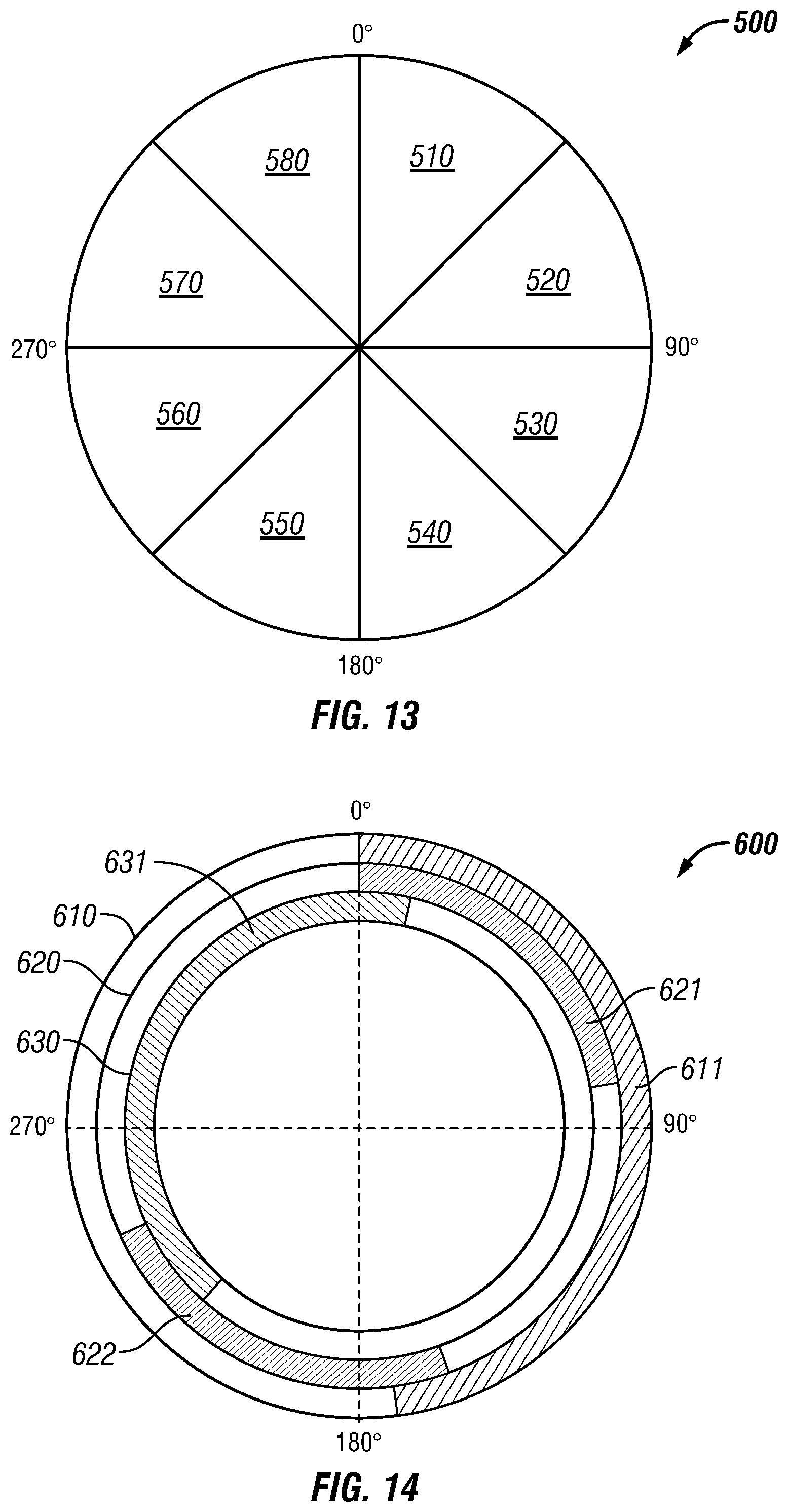
D00014

D00015

D00016

D00017

D00018

D00019
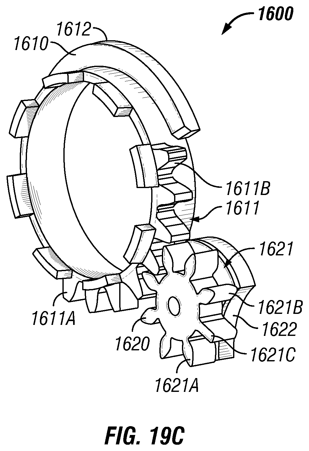
D00020

D00021

XML
uspto.report is an independent third-party trademark research tool that is not affiliated, endorsed, or sponsored by the United States Patent and Trademark Office (USPTO) or any other governmental organization. The information provided by uspto.report is based on publicly available data at the time of writing and is intended for informational purposes only.
While we strive to provide accurate and up-to-date information, we do not guarantee the accuracy, completeness, reliability, or suitability of the information displayed on this site. The use of this site is at your own risk. Any reliance you place on such information is therefore strictly at your own risk.
All official trademark data, including owner information, should be verified by visiting the official USPTO website at www.uspto.gov. This site is not intended to replace professional legal advice and should not be used as a substitute for consulting with a legal professional who is knowledgeable about trademark law.