Top Toy
MURAKI; Makoto ; et al.
U.S. patent application number 16/800457 was filed with the patent office on 2020-08-27 for top toy. This patent application is currently assigned to TOMY COMPANY, LTD.. The applicant listed for this patent is TOMY COMPANY, LTD.. Invention is credited to Yohei BANDO, Takeaki MAEDA, Makoto MURAKI.
| Application Number | 20200269147 16/800457 |
| Document ID | / |
| Family ID | 1000004704822 |
| Filed Date | 2020-08-27 |


| United States Patent Application | 20200269147 |
| Kind Code | A1 |
| MURAKI; Makoto ; et al. | August 27, 2020 |
TOP TOY
Abstract
A top toy includes a body and a shaft part being detachably attached to the body. The body includes a trunk main body, a first tip, and a second tip. The trunk main body includes an arc shaped hole with first and second ends. First and second insertion pieces of the first and second tips respectively are inserted in the arc shaped hole at the first and second ends respectively. The trunk main body includes a moving part being manually operated between first and second positions. In the second direction, a space, the resistance element, the first coupling member are aligned in order when the first tip is employed. In the first direction, the space, the second coupling member, and the resistance element are aligned in order when the second tip is employed. The body and the shaft part are to be detached at the space.
| Inventors: | MURAKI; Makoto; (Tokyo, JP) ; BANDO; Yohei; (Tokyo, JP) ; MAEDA; Takeaki; (Tokyo, JP) | ||||||||||
| Applicant: |
|
||||||||||
|---|---|---|---|---|---|---|---|---|---|---|---|
| Assignee: | TOMY COMPANY, LTD. Tokyo JP |
||||||||||
| Family ID: | 1000004704822 | ||||||||||
| Appl. No.: | 16/800457 | ||||||||||
| Filed: | February 25, 2020 |
| Current U.S. Class: | 1/1 |
| Current CPC Class: | A63F 9/16 20130101; A63H 1/02 20130101 |
| International Class: | A63H 1/02 20060101 A63H001/02 |
Foreign Application Data
| Date | Code | Application Number |
|---|---|---|
| Feb 26, 2019 | JP | 2019-033125 |
Claims
1. A top toy comprising: a body; and a shaft part being detachably attached to the body, the shaft part extending in an axial direction, the body including a trunk main body including a first coupling member, a first tip being attached to the trunk main body when employed for the top toy to be rotated in a first direction, and a second tip being attached to the trunk main body when employed for the top toy to be rotated in a second direction opposite to the first direction, the first and second tips being interchangeable, the shaft part including a second coupling member being coupled with the first coupling member, the first tip including a first insertion piece extending downwardly, the first insertion piece including a first resistance element at a bottom thereof, the second tip including a second insertion piece extending downwardly, the second insertion piece including a second resistance element at a bottom thereof, the trunk main body including an arc shaped hole having a first end and a second end opposite to the first end, the first insertion piece being inserted in the arc shaped hole at the first end, the second insertion piece being inserted in the arc shaped hold at the second end, the trunk main body including a moving part being configured to be manually operated by a user between first and second positions, in the second direction, a space, the resistance element, the first coupling member being aligned in order when the first tip is employed, in the first direction, the space, the second coupling member, and the resistance element being aligned in order when the second tip is employed, the body and the shaft part being to be detached at the space.
2. The top toy according to claim 1, wherein the moving part includes an insertion prevention part being configured to prevent the second insertion piece for being inserted at the first position, and to prevent the first insertion piece from being inserted at the second position.
3. The top toy according to claim 1, wherein the trunk main body includes an arc shaped slit and a locked part, the first tip includes a first locked part, the second tip includes a second locked part, the arc shaped slit having a diameter with a center being formed concentrically with the shaft part, a fork of a launcher of the top toy is to be inserted in arc shaped slit, the fork includes a locking part being configured to lock the first locked part at a first longitudinal direction end part of the arc shaped slit when the first tip is employed, the locking part is configured to lock the second locked part at a second longitudinal direction end part of the arc shaped slit when the second tip is employed, when rotational force is provided by rotation of the fork, the first locked part is configured to be released by stopping rotation of the fork, when rotational force is provided by rotation of the fork, the second locked part is configured to be released by stopping rotation of the fork.
Description
CROSS-REFERENCE TO THE RELATED APPLICATION
[0001] The present application claims priority under 35 U.S.C. 119 to Japanese Patent Application No. 2019-033125 filed on Feb. 26, 2019. The entire content of Japanese Patent Application No. 2019-033125 is incorporated herein by reference.
BACKGROUND
Technical Field
[0002] The present invention relates to a top toy.
Background Art
[0003] Conventionally known is a toy configured from a clockwise rotation top toy, a counterclockwise rotation top toy, and a launcher that comprises a launcher for rotating these top toys clockwise or counterclockwise (see Patent Document 1, for example).
[0004] [Patent Document 1] Utility Model Registration Publication No. 3071356
SUMMARY
Problems the Invention Is Intended to Solve
[0005] However, this top toy has a structure in which by matching the body and the shaft part from the axis center direction and rotating the body with respect to the shaft part in the rotation direction of the top toy, the top surface of a first claw on the body side and the bottom surface of a second claw on the shaft part side abut, coupling the body and the shaft part, and when an external impact acts on the body, when the body rotates with respect to the shaft part in the direction opposite to the rotation direction of the top toy, the coupling is released. Also, simultaneous with abutting of the top surface of the first claw of the body side and the bottom surface of the second claw of the shaft part side, the body side resistance element and the shaft part side resistance element are engaged. Then, relative rotation of the body and the shaft part is made to be performed in stages.
[0006] The rotation direction of the body and the shaft part differs between the clockwise rotation top toy and the counterclockwise rotation top toy, so the position of the first claw and the resistance element formed on the body is different. In light of that, in the past, a clockwise rotation body, and a counterclockwise rotation body for which the installation position of the first claw and the resistance element differs was used.
[0007] However, the body is relatively expensive because it occupies a large volume of the top toy.
[0008] The present invention was created considering these problems, and its purpose is to provide a relatively inexpensive top toy with which the rotation direction can be easily changed by replacing small parts.
Means for Solving the Problems
[0009] A top toy includes a body and a shaft part being detachably attached to the body. The shaft part extends in an axial direction.
[0010] The body includes a trunk main body including a first coupling member, a first tip being attached to the trunk main body when employed for the top toy to be rotated in a first direction, and a second tip being attached to the trunk main body when employed for the top toy to be rotated in a second direction opposite to the first direction. The first and second tips are interchangeable.
[0011] The shaft part includes a second coupling member being coupled with the first coupling member. The first tip includes a first insertion piece extending downwardly. The first insertion piece includes a first resistance element at a bottom thereof. The second tip includes a second insertion piece extending downwardly. The second insertion piece includes a second resistance element at a bottom thereof.
[0012] The trunk main body includes an arc shaped hole having a first end and a second end opposite to the first end.
[0013] The first insertion piece is inserted in the arc shaped hole at the first end. The second insertion piece is inserted in the arc shaped hold at the second end. The trunk main body includes a moving part being configured to be manually operated by a user between first and second positions.
[0014] In the second direction, a space, the resistance element, the first coupling member being aligned in order when the first tip is employed. In the first direction, the space, the second coupling member, and the resistance element being aligned in order when the second tip is employed.
[0015] The body and the shaft part are to be detached at the space.
BRIEF DESCRIPTION OF THE DRAWINGS
[0016] FIG. 1 is a perspective view showing a top toy and a launcher of an embodiment.
[0017] FIG. 2 is an exploded perspective view of the top toy.
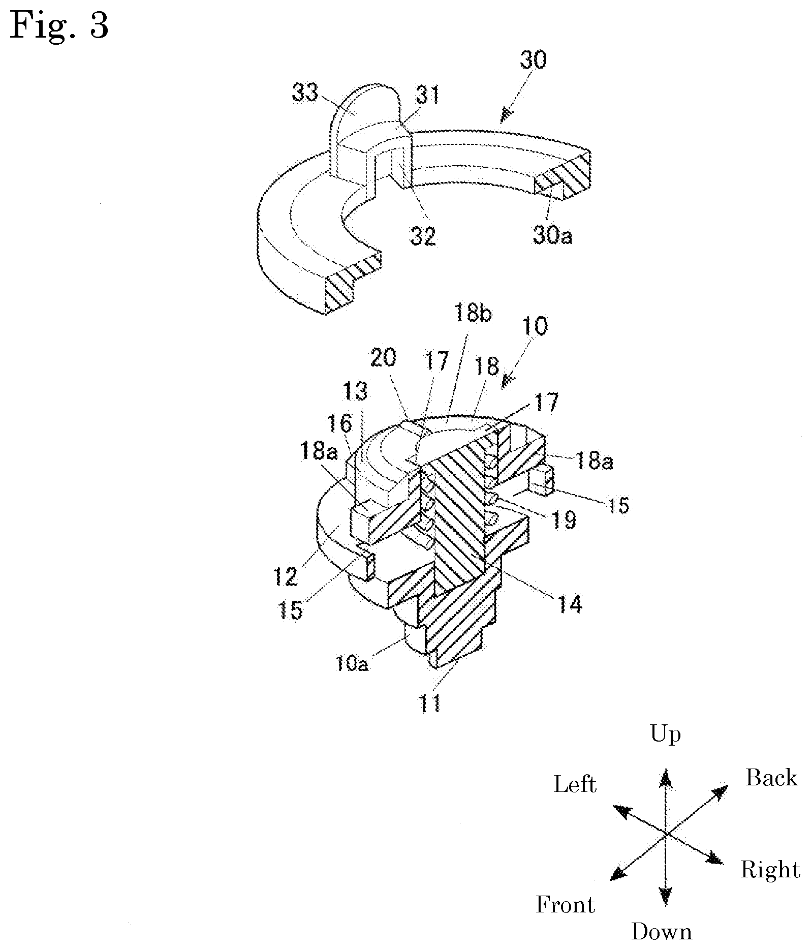
[0018] FIG. 3 is an exploded perspective view showing a cross section of the shaft part and a portion of the top toy of the present embodiment.
[0019] FIG. 4 is a plan view of the body with the tip removed seen from above.
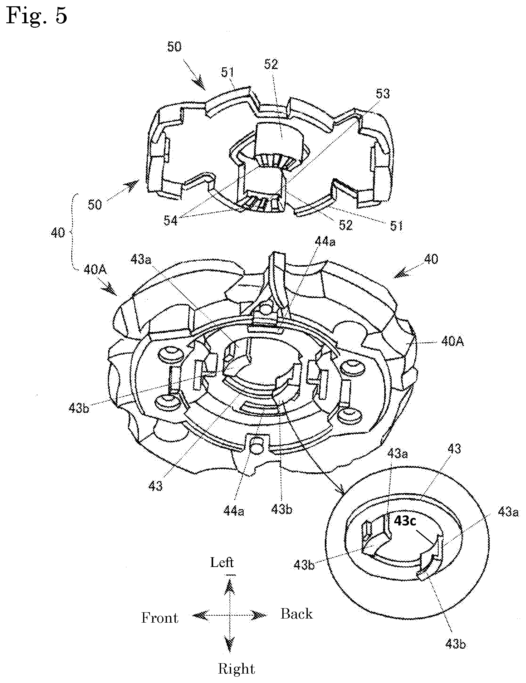
[0020] FIG. 5 is a perspective view of a trunk part and the tip mounted on the trunk part seen from below.
[0021] FIGS. 6A and 6B are bottom views of the trunk part and the tip when the top toy is rotated clockwise, where FIG. 6A shows the body in a state with the tip detached, and FIG. 6B shows the tip for clockwise rotation.
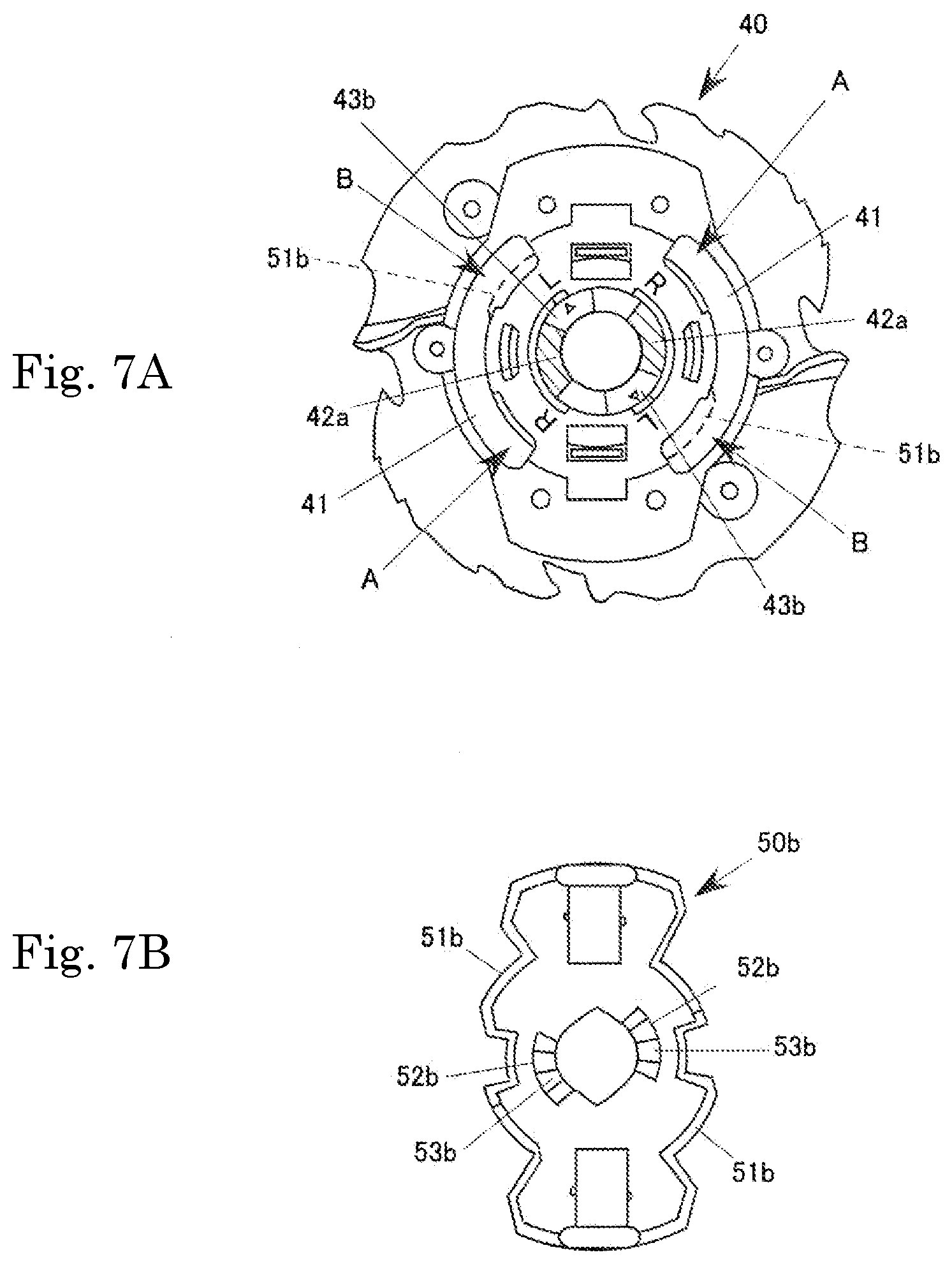
[0022] FIGS. 7A and 7B are bottom views of the trunk part and the tip when the top toy is rotated counterclockwise, where FIG. 7A shows the body in a state with the tip detached, and FIG. 7B shows the tip for counterclockwise rotation.
DETAILED DESCRIPTION OF THE PREFERRED EMBODIMENTS
[0023] Following, the top toy of the present invention is explained based on an embodiment shown in the drawings. In the specification, up and down, left and right, and front and rear mean the directions shown in FIG. 2.
Overall Configuration
[0024] FIG. 1 is a perspective view showing the top toy and the launcher of the embodiment.
[0025] This top toy 1 is configured by a shaft part 10 that configures the lower structure, and a variable performance ring 30 and a body 40 that configure the upper structure.
[0026] This top toy 1 has rotational force given by a launcher (top shooting device) 60, and is released into a battlefield.
Detailed Configuration
[0027] 1. Shaft Part 10
[0028] As shown in FIG. 2, the shaft part 10 comprises a rotation shaft 11 at the lower part, a flange 12 in the middle part, and a cylindrical part 13 in the upper part. The rotation shaft 11, the flange 12, and the cylindrical part 13 are formed using synthetic resin. Of course, the material is not limited to a synthetic resin, and the entirety or a portion may also be formed using metal or rubber, or another material.
[0029] The lower part of the flange 12 of the shaft part 10 has a shape that is constricted in stages facing from the flange 12 toward the rotation shaft 11, and overall, forms substantially an inverted cone shape.
[0030] One hole 15 each is formed front and rear on the flange 12 and the cylindrical part 13. Also, on the flange 12 and the cylindrical part 13, protruding parts 16 are formed at left and right of the flange 12. These protruding parts 16 are positioned at top and bottom of the flange 12, and the outer surface is flush with the outer circumference surface of the flange 12.
[0031] Also, as shown in FIG. 3, a cylindrical body 14 is erected on the inside of the cylindrical part 13. The top end of this cylindrical body 14 is not particularly limited, but is set at a position slightly higher than the top end of the cylindrical part 13. One each of a claw (example of the first coupling member) 17 protruding radially outward is formed front and rear on the top end part of this cylindrical body 14.
[0032] Also, the shaft part 10 comprises a cylindrical moving member 18 that is provided on the inside of the cylindrical part 13 and that surrounds the upper outer circumference of the cylindrical body 14. One each of a projecting piece 18a that protrudes radially outward at front and rear is formed on the lower end part of this moving member 18. Each projecting piece 18a is inserted in the hole 15. The moving member 18 is able to move in the vertical direction. Also, the moving member 18 is energized upward by a coil spring 19 that is wound around the cylindrical body 14, and normally, the projecting piece 18a abuts the top edge of the hole 15.
[0033] One each of a convex strip (resistance element) 20 is formed extending in the radial direction left and right on the top surface 18b of this moving member 18. [0034] 2. Variable Performance Ring 30
[0035] With this embodiment, a flywheel made of metal is used as the variable performance ring 30, for example. The variable performance ring 30 has substantially a plate shape. An annular step part 30a that can house the flange 12 of the shaft part 10 from below is formed on the bottom surface of this variable performance ring 30. Also, one inverse U-shaped protruding part 31 each protruding facing upward respectively at left and right is formed on the top surface of this variable performance ring 30. A concave part 32 that can house the protruding part 16 of the shaft part 10 from below is formed on the lower part of each protruding part 31. Meanwhile, a tongue piece 33 protruding upward just outside of each protruding part 31 is formed on the top surface of the variable performance ring 30.
[0036] As this variable performance ring 30, instead of the flywheel, or being integrally formed with the flywheel, this can be an item that has a protruding part on the outer circumference surface and makes it easy to attack the top toy 1 of the other party, or an item that has a concave part on the outer circumference surface and is less susceptible to attacks from the top toy 1 of the other party. [0037] 3. Body 40
[0038] As shown in FIG. 5, the body 40 comprises a trunk body 40A (example of the trunk main body) and a tip 50, and overall forms a disk shape. As shown in FIG. 4, one each of an arc shaped slit 41 is formed left and right on a ceiling wall 40a of the trunk body 40A. The arc shaped slit 41 is formed concentrically on the axis center of the body 40. Also, at the top surface center part of the ceiling wall 40a of the trunk body 40A, a concave part 40b that houses the tip 50 is defined. A plate 42 of substantially the same shape as the concave part 40b is housed in the concave part 40b.
[0039] One each of an arc shaped hole 42a is formed at left and right on the plate 42. The arc shaped hole 42a is formed concentrically with the axis center of the body 40. Also, as shown in FIG. 5, an annular disk 43 is attached to the plate 42. For example, the annular disk 43 is installed sandwiched between two claws 44a, 44a and the plate 42. Of course it is also possible to install in another manner. In brief, the annular disk 43 should not separate easily. As shown enlarged in FIG. 5, on this annular disk 43, one each of a projecting piece 43a is erected facing downward at two locations of the part sandwiching and opposing the axis center. With each projecting piece 43a, the horizontal cross section forms an arc shape, and on the bottom end is formed a first claw 43b (example of the second coupling member) protruding facing radially inward. This projecting piece 43a is provided projecting inward from the body of the annular disk 43. The top end of this projecting piece 43a configures an insertion prevention part 43c. [0040] 4. Tip 50
[0041] First, a clockwise rotation tip 50a and a counterclockwise rotation tip 50b are explained collectively as the tip 50 using FIG. 5. The clockwise rotation tip 50a and the counterclockwise rotation tip 50b are examples of the first and second tips. Incidentally, the clockwise rotation tip 50a is shown in FIG. 5, and the common parts are explained using this FIG. 5.
[0042] The tip 50 is a board shaped body housed in the concave part 40b, and is used fitted in the concave part 40b.
[0043] With the tip 50, a locked part 51 is formed for narrowing the width of the end part of the arc shaped slit 41 on the outer circumference part, and an insertion piece 52 is formed on the bottom surface. Of these, the locked part 51 forms a part locked by a projection (locking part) 63b of a fork 63 of the launcher 60 described later that narrows the width of one end part of the arc shaped slit 41. Also, a claw 53 projecting radially inward is provided on the bottom end of the insertion piece 52, and on the bottom surface of the claw 53 is formed a plurality of convex strips (resistance elements) 54 that engage with the convex strip 20 of the shaft part 10. This plurality of convex strips 54 functions together with the convex strip 20 as rotation resistance with the body 40 and the shaft part 10.
[0044] With the top toy 1 of the embodiment, as this tip 50, comprised are the clockwise rotation tip 50a (FIG. 6B) and the counterclockwise rotation tip 50b (FIG. 7B). The formation position of the locked part 51 and the insertion piece 52 are mutually different with the clockwise rotation tip 50a and the counterclockwise rotation tip 50b.
[0045] As shown in FIG. 6A and 6B, formed on the clockwise rotation tip 50a is a locked part 51a that can narrow the width of the clockwise side end part of the arc shaped slit 41 when mounted on the trunk body 40A. Also, on the clockwise rotation tip 50a, an insertion piece 52a is formed at the position of insertion in the counterclockwise side end part of the arc shaped hole 42a in a top view when mounted on the trunk body 40A.
[0046] Meanwhile, on the counterclockwise rotation tip 50b, as shown in FIG. 7A and 7B, a locked part 51b is formed at a position that can narrow the width of the end part of the counterclockwise side of the arc shaped slit 41 in the top view when mounted on the trunk body 40A. Also, on the counterclockwise rotation tip 50b, formed is an insertion piece 52b at the position of insertion in the clockwise side end part of the arc shaped hole 42a with the top view when mounted on the trunk body 40A.
[0047] Then, the clockwise rotation tip 50a and the counterclockwise rotation tip 50b are fitted to the concave part 40b in a state with the insertion pieces 52a, 52b inserted in the arc shaped holes 42a, 42a. [0048] 5. Launcher 60
[0049] Charging of the rotational force of the top toy 1 is performed using the launcher 60 like that shown in FIG. 1. The top toy 1 is mounted in this launcher 60. Specifically, the fork 63 is inserted in the arc shaped slit 41 of the body 40. Then, the locked part 51 of the body 40 is engaged with the projection 63b. By doing this, the top toy 1 is mounted on the launcher 60.
[0050] This launcher 60 comprises a disk (not illustrated) inside, and the configuration is such that this disk is energized in one rotation direction by a spiral spring (not illustrated), and also, when a cord (not illustrated) wound around the disk is pulled using a handle 61, the disk rotates, and a top holder 62 rotates. The rotation of this top holder 62 is transmitted to the top toy 1 by the fork 63 provided protruding downward, and the top toy 1 is rotated in one rotation direction. To rotate the top toy 1 in the other rotation direction with the launcher 60, the internal gear of the launcher 60 is switched, or another launcher 60 is used.
[0051] Then, when the handle 61 of the launcher 60 is pulled all the way, while the rotation of the disk and thus the top holder 62 is stopped, the top toy 1 still rotates by inertia, so it follows an inclined surface 63a of the fork 63 and the top toy 1 separates from the top holder 62. [0052] 6. Positional Relationship of Body 40, Tip 50
[0053] FIGS. 6A and 6B are bottom surface views showing the positional relationship of the body 40 of the top toy 1 and the clockwise rotation tip 50a when rotated clockwise. When attempting to rotate this top toy 1 clockwise, first, the annular disk 43 is rotated to an R position. In this state, the clockwise end part of the arc shaped hole 42a of the plate 42 is blocked. Then, the insertion piece 52a of the clockwise rotation tip 50a is inserted in the unblocked part (shaded part) of the arc shaped hole 42a, the clockwise rotation tip 50a is fitted with the concave part 40b (see FIG. 4) defined on the top surface of the body 40 and fixed to the body 40.
[0054] With the top toy 1 in this state, the locked part 51a of the clockwise rotation tip 50a is erected on the clockwise side end part of the arc shaped slit 41, in other words, the A part, and the width of the end part of the arc shaped slit 41 is narrowed.
[0055] Then, the second claw 17 of the shaft part 10 is engaged with this trunk part 40. Specifically, the claw 17 of the shaft part 10 and the claw (first claw) 43b of the annular disk 43 of the body 40 are in a coupled state overlapping vertically. Also, the convex strip 54a of the clockwise rotation tip 50a is engaged with the convex strip 20 of the moving member 18.
[0056] FIGS. 7A and 7Bares bottom surface views showing the positional relationship of the body 40 of the top toy 1 and the counterclockwise rotation tip 50b when rotated counterclockwise. When attempting to rotate this top toy 1 counterclockwise, first, the annular disk 43 is rotated to an L position. In this state, the counterclockwise end part of the arc shaped hole 42a of the plate 42 is blocked. Then, the insertion piece 52b of the counterclockwise rotation tip 50b is inserted in the unblocked part (shaded part) of the arc shaped hole 42a, the counterclockwise rotation tip 50b is fitted to the concave part 40b (see FIG. 4) defined on the top surface of the body 40, and fixed to the body 40.
[0057] With the top toy 1 in this state, the locked part 51b of the counterclockwise rotation tip 50b is positioned at the counterclockwise side end part of the two arc shaped slits 41, in other words, the B part, narrowing the width of the end part of the arc shaped slit 41.
[0058] Then, the second claw 17 of the shaft part 10 is engaged with this trunk part 40. Specifically, the claw 17 of the shaft part 10 and the claw (first claw) 43b of the annular disk 43 of the body 40 are in a coupled state overlapping in the vertical direction. Also, the convex strip 54b of the counterclockwise rotation tip 50b is engaged with the convex strip 20 of the moving member 18.
[0059] With the top toy 1 of this embodiment, after positioning the annular disk 43 in advance at the clockwise rotation position R or the counterclockwise rotation position L, by selectively mounting on the body 40 the clockwise rotation tip 50a or the counterclockwise rotation tip 50b suited to that, it is possible to change the body 40 to the body 40 for clockwise rotation or for counterclockwise rotation.
[0060] In this top toy 1, when an attempt is made to attach the counterclockwise rotation tip 50b to the body 40 in a state with the annular disk 43 positioned at the clockwise rotation position R, for example, since the insertion prevention part 43c is positioned at the position of the arc shaped hole 42a, the counterclockwise rotation tip 50b cannot be mounted in the body 40. The reverse is also the same. Therefore, accidental mounting of the tip 50 is prevented.
[0061] Above, an embodiment of the present invention was explained, but the present invention is not limited to this embodiment, and it goes without saying that various modifications are possible within a range that does not stray from the gist of the invention.
Effect of the Invention
[0062] It is possible to change the position of the first coupling element and the resistance element according to the rotation direction, so even if the rotation direction changes, it is possible to appropriately perform coupling of the body and the shaft part. Also, it is possible to easily change the rotation direction simply by replacing the tip and operating the moving part, realizing an inexpensive top toy. Furthermore, it is possible to change the rotation direction while changing the characteristics of the resistance element (irregularity count, material, inclination, etc.).
[0063] It is possible to prevent in advance accidental mounting of a tip of a different rotation direction.
[0064] It is possible to change the position of the locked part according to the rotation direction, so it is possible to reliably give rotational force to the top toy using the launcher.
[0065] The above and/or other aspects, features and/or advantages of various embodiments will be further appreciated in view of the following description in conjunction with the accompanying figures. Various embodiments can include and/or exclude different aspects, features and/or advantages where applicable. In addition, various embodiments can combine one or more aspect or feature of other embodiments where applicable. The descriptions of aspects, features and/or advantages of particular embodiments should not be construed as limiting other embodiments or the claims. In the drawings, the size and relative sizes of layers and regions may be exaggerated for clarity. Like numbers refer to like elements throughout. The terminology used herein is for the purpose of describing particular embodiments only and is not intended to be limiting of the invention. As used herein, the singular forms "a", "an" and "the" are intended to include the plural forms as well, unless the context clearly indicates otherwise. As used herein, the term "and/or" includes any and all combinations of one or more of the associated listed items and may be abbreviated as "/". It will be understood that, although the terms first, second, etc. may be used herein to describe various elements, these elements should not be limited by these terms. Unless indicated otherwise, these terms are only used to distinguish one element from another. For example, a first object could be termed a second object, and, similarly, a second object could be termed a first object without departing from the teachings of the disclosure. It will be further understood that the terms "comprises" and/or "comprising," or "includes" and/or "including" when used in this specification, specify the presence of stated features, regions, integers, steps, operations, elements, and/or components, but do not preclude the presence or addition of one or more other features, regions, integers, steps, operations, elements, components, and/or groups thereof. It will be understood that when an element is referred to as being "connected" or "coupled" to or "on" another element, it can be directly connected or coupled to or on the other element or intervening elements may be present. In contrast, when an element is referred to as being "directly connected" or "directly coupled" to another element, there are no intervening elements present. Other words used to describe the relationship between elements should be interpreted in a like fashion (e.g., "between" versus "directly between," "adjacent" versus "directly adjacent," etc.). However, the term "contact," as used herein refers to direct contact (i.e., touching) unless the context indicates otherwise. Terms such as "same," "planar," or "coplanar," as used herein when referring to orientation, layout, location, shapes, sizes, amounts, or other measures do not necessarily mean an exactly identical orientation, layout, location, shape, size, amount, or other measure, but are intended to encompass nearly identical orientation, layout, location, shapes, sizes, amounts, or other measures within acceptable variations that may occur, for example, due to manufacturing processes. The term "substantially" may be used herein to reflect this meaning. Unless otherwise defined, all terms (including technical and scientific terms) used herein have the same meaning as commonly understood by one of ordinary skill in the art to which this disclosure belongs. It will be further understood that terms, such as those defined in commonly used dictionaries, should be interpreted as having a meaning that is consistent with their meaning in the context of the relevant art and/or the present application, and will not be interpreted in an idealized or overly formal sense unless expressly so defined herein.
* * * * *
D00000
D00001
D00002
D00003
D00004
D00005
D00006
D00007
XML
uspto.report is an independent third-party trademark research tool that is not affiliated, endorsed, or sponsored by the United States Patent and Trademark Office (USPTO) or any other governmental organization. The information provided by uspto.report is based on publicly available data at the time of writing and is intended for informational purposes only.
While we strive to provide accurate and up-to-date information, we do not guarantee the accuracy, completeness, reliability, or suitability of the information displayed on this site. The use of this site is at your own risk. Any reliance you place on such information is therefore strictly at your own risk.
All official trademark data, including owner information, should be verified by visiting the official USPTO website at www.uspto.gov. This site is not intended to replace professional legal advice and should not be used as a substitute for consulting with a legal professional who is knowledgeable about trademark law.