Top Toy
MURAKI; Makoto ; et al.
U.S. patent application number 16/797614 was filed with the patent office on 2020-08-27 for top toy. This patent application is currently assigned to TOMY COMPANY, LTD.. The applicant listed for this patent is TOMY COMPANY, LTD.. Invention is credited to Yohei BANDO, Takeaki MAEDA, Makoto MURAKI.
| Application Number | 20200269146 16/797614 |
| Document ID | / |
| Family ID | 1000004702568 |
| Filed Date | 2020-08-27 |


| United States Patent Application | 20200269146 |
| Kind Code | A1 |
| MURAKI; Makoto ; et al. | August 27, 2020 |
TOP TOY
Abstract
A top toy includes a body including a first coupling element, and a shaft part being detachably attached to the body and including a second coupling element and a projection. The first and second coupling elements abut each. The body and the shaft part are detachable when the body is rotated relative to the shaft part. The body includes a rotating blade being configured on an outer circumference part thereof to be rotated. The rotating blade includes a shaft extending parallel to the axial direction and is configure to advance and retreat with respect to the arc shaped slit. The rotating blade includes a sliding part at an inner edge which is formed in a bow shape. The rotating blade is configured to be rotated around the shaft by the sliding part being slidably in contact with the projection.
| Inventors: | MURAKI; Makoto; (Tokyo, JP) ; BANDO; Yohei; (Tokyo, JP) ; MAEDA; Takeaki; (Tokyo, JP) | ||||||||||
| Applicant: |
|
||||||||||
|---|---|---|---|---|---|---|---|---|---|---|---|
| Assignee: | TOMY COMPANY, LTD. Tokyo JP |
||||||||||
| Family ID: | 1000004702568 | ||||||||||
| Appl. No.: | 16/797614 | ||||||||||
| Filed: | February 21, 2020 |
| Current U.S. Class: | 1/1 |
| Current CPC Class: | A63F 9/16 20130101; A63H 1/02 20130101 |
| International Class: | A63H 1/02 20060101 A63H001/02 |
Foreign Application Data
| Date | Code | Application Number |
|---|---|---|
| Feb 26, 2019 | JP | 2019-033198 |
Claims
1. A top toy comprising: a body including a first coupling element, and a shaft part being detachably attached to the body and including a second coupling element and a projection, the shaft part extending in an axial direction, the first and second coupling elements abutting each other in the axial direction in a state in which the body and the shaft part are attached, the body and the shaft part being detachable when the body is rotated relative to the shaft part, the body includes an arc shaped slit in which the projection is inserted, the body includes a rotating blade being configured on an outer circumference part thereof to be rotated, the rotating blade including a shaft extending parallel to the axial direction, the rotating blade being configure to advance and retreat with respect to the arc shaped slit, the rotating blade includes a sliding part at an inner edge thereof, the inner edge being formed in a bow shape, the rotating blade being configured to be rotated around the shaft by the sliding part being slidably in contact with the projection to advance and retreat with respect to the arc shaped slit.
2. The top toy according to claim 1, wherein the rotating blade, when the projection moves within the arc shaped slit in the direction in which coupling between the first and second coupling elements is released, the rotating blade includes a blade function part being configured to operate radially outward, and when an external impact is applied to the rotating blade, the projection is pushed back.
3. The top toy of claim 1, characterized in that with the rotating blade the rotating blade includes a blade function part, and when the projection moves within the arc shaped slit in the direction in which coupling between the first and second coupling elements is released, the blade function part operates radially inward.
Description
CROSS-REFERENCE TO THE RELATED APPLICATION
[0001] The present application claims priority under 35 U.S.C. 119 to Japanese Patent Application No. 2019-033198 filed on Feb. 26, 2019. The entire content of Japanese Patent Application No. 2019-033198 is incorporated herein by reference.
BACKGROUND
Technical Field
[0002] The present invention relates to a top toy, and particularly relates to a top toy suitable for a battle game.
Background Art
[0003] Conventionally known as a top toy is a top toy comprising a body on which a first coupling element is formed, and a shaft part on which a second coupling element is formed, the top toy having a structure with which by having the top surface of the first coupling element and the bottom surface of the second coupling element be abutted in a state for which the body and the shaft part are matched from the axis center direction, the body and the shaft part are coupled, and when an external impact acts on the body, the body and the shaft part rotate relatively, the coupling is released, and they are disassembled (see Patent Document 1, for example).
[0004] [Patent Document 1] Patent Publication No. 6377211
SUMMARY
Problems the Invention is Intended to Solve
[0005] With this top toy, a movable blade was operated using centrifugal force to change the shape of the blade of the entire top toy.
[0006] The present invention was created considering these problems, and its purpose is to provide a top toy with which it is possible to change the shape of the blade during rotation using a different simple structure.
Means for Solving the Problems
[0007] A top toy includes a body including a first coupling element, and a shaft part being detachably attached to the body and including a second coupling element and a projection. The shaft part extends in an axial direction.
[0008] The first and second coupling elements abut each other in the axial direction in a state in which the body and the shaft part are attached.
[0009] The body and the shaft part are detachable when the body is rotated relative to the shaft part. The body includes an arc shaped slit in which the projection is inserted. The body includes a rotating blade being configured on an outer circumference part thereof to be rotated.
[0010] The rotating blade includes a shaft extending parallel to the axial direction. The rotating blade being configure to advance and retreat with respect to the arc shaped slit. The rotating blade includes a sliding part at an inner edge thereof. The inner edge is formed in a bow shape. The rotating blade is configured to be rotated around the shaft by the sliding part being slidably in contact with the projection to advance and retreat with respect to the arc shaped slit.
BRIEF DESCRIPTION OF THE DRAWINGS
[0011] FIG. 1 is a perspective view of a top toy of an embodiment.
[0012] FIG. 2 is a perspective view of the top toy shown in FIG. 1 in a disassembled state.
[0013] FIG. 3 is a perspective view of half of a shaft part and a variable performance ring.
[0014] FIG. 4 is a perspective view of a body seen from below.
[0015] FIG. 5 is an exploded perspective view for explaining the configuration of the body.
[0016] FIGS. 6A and 6B are plan views for explaining the action of the top toy.
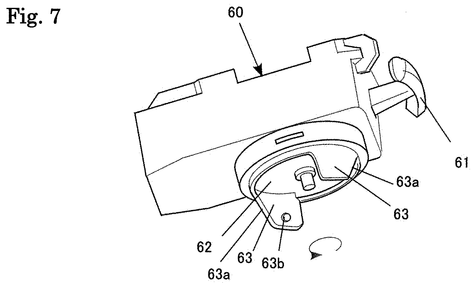
[0017] FIG. 7 is a perspective view of a launcher.
DETAILED DESCRIPTION OF PREFERRED EMBODIMENTS
[0018] Following, the top toy of the present invention is explained based on an embodiment shown in the drawings.
Overall Structure
[0019] FIG. 1 is a perspective view showing a top toy 1 of the present embodiment, and FIG. 2 is a perspective view of the top toy 1 in a disassembled state.
[0020] This top toy 1 is a top toy that can be used in a so-called battle game. This top toy 1 can be used in a battle game in which winning occurs by disassembling the other party's top toy 1 by the impact force of colliding with each other as shown in FIG. 2.
[0021] This top toy 1 is configured by a shaft part 10, a variable performance ring 30, and a body 40.
Details
1. Shaft Part 10
[0022] FIG. 3 is an exploded perspective view showing half of the shaft part 10 and the variable performance ring 30. The remaining half has a symmetrical shape.
[0023] The shaft part 10 comprises a rotation shaft 11 in the lower part, a flange 12 in the middle part, and a cylindrical part 13 in the upper part. The rotation shaft 11, the flange 12, and the cylindrical part 13 are formed using synthetic resin. Of course, the material is not limited to a synthetic resin, and the entirety or a portion may also be formed using metal or rubber, or another material.
[0024] The lower part of the flange 12 of the shaft part 10 has a shape that is constricted in stages facing from the flange 12 toward the rotation shaft 11, and overall, forms substantially an inverted cone shape.
[0025] One hole 15 each is formed front and rear on the flange 12 and the cylindrical part 13. Also, on the flange 12 and the cylindrical part 13, one protruding part 16 each is formed at left and right of the flange 12. These protruding parts 16 are positioned at top and bottom of the flange 12, and the outer surface is flush with the outer circumference surface of the flange 12.
[0026] Also, a cylindrical body 14 is erected on the inside of the cylindrical part 13. The top end of this cylindrical body 14 is not particularly limited, but is set at a position slightly higher than the top end of the cylindrical part 13. One each of a claw (first coupling element) 17 protruding radially outward is formed front and rear on the top end part of this cylindrical body 14.
[0027] Also, the shaft part 10 comprises a cylindrical moving member 18 that is provided on the inside of the cylindrical part 13 and that surrounds the upper outer circumference of the cylindrical body 14. One each of a projecting piece 18a that protrudes radially outward at front and rear is formed on the lower end part of this moving member 18. Each projecting piece 18a is inserted in the hole 15. The moving member 18 is able to move in the vertical direction. Also, the moving member 18 is energized upward by a coil spring 19 that is wound around the cylindrical body 14, and normally, the projecting piece 18a abuts the top edge of the hole 15.
[0028] One each of a convex strip (resistance element) 20 is formed extending in the radial direction at left and right on the top surface 18b of this moving member 18.
2. Variable Performance Ring 30
[0029] With this embodiment, a flywheel made of metal is used as the variable performance ring 30, for example. The variable performance ring 30 has substantially a plate shape. An annular step part 30a that can house the flange 12 of the shaft part 10 from below is formed on the bottom surface of this variable performance ring 30. Also, one inverse U-shaped protruding part 31 each protruding facing upward respectively in the lateral direction is formed on the top surface of this variable performance ring 30. A concave part 32 that can house the protruding part 16 of the shaft part 10 from below is formed on the lower part of each protruding part 31. Meanwhile, a tongue piece 33 (an example of the projection) protruding upward just outside of each protruding part 31 is formed on the top surface of the variable performance ring 30.
[0030] As this variable performance ring 30, instead of the flywheel, or being integrally formed with the flywheel, this can be an item that has a protruding part on the outer circumference surface and makes it easy to attack the top toy 1 of the other party, or an item that has a concave part on the outer circumference surface and is less susceptible to attacks from the top toy 1 of the other party.
3. Body 40
[0031] FIG. 4 is a perspective view of the body 40 seen from below, FIG. 5 is an exploded perspective view of the body 40, and FIGS. 6A and 6B are plan views for explaining the action of the top toy.
[0032] The body 40 comprises a trunk main body 40a, a weight 40b, and a tip 40c, and the body 40 is configured by assembling these.
[0033] The trunk main body 40a comprises a ceiling wall 42, and is formed in a disk shape. At the bottom end surface of an annular wall 43 of the inside of the trunk main body 40a, claws 44 extending radially inward are provided projecting at two symmetrical positions. Also, at the bottom end surface of the projection of the tip 40c, a corrugated part (resistance element) 45 for which unevenness is continuously formed extending in the radial direction is formed at two symmetrical positions, and this corrugated part 45 meshes with the convex strip (resistance element) 20 of the shaft part 10.
[0034] Also, arc shaped slits 46 for which the tongue piece 33 of the variable performance ring 30 can be inserted from below are respectively formed at two symmetrical positions on the trunk main body 40a. The circumference direction length of each arc shaped slit 46 is a length by which the tongue piece 33 can move sufficiently.
[0035] A blade 47 is arranged along the entire circumference on the outer circumference of the trunk main body 40a. With the top toy 1 of the embodiment, as the blade 47, an upper blade 48 and a lower blade 49 are comprised.
[0036] Of these, the upper blade 48 is a series of fixed blades having a corrugated form for the external form. Meanwhile, as shown in FIGS. 6A and 6B, the lower blade 49 is configured from two fixed blades 49a having a corrugated form for the external form respectively formed at two symmetrical positions, and two rotating blades 51 having a corrugated form for the external form respectively arranged at two symmetrical positions, and has a form for which the fixed blades 49a and the rotating blades 51 are arranged alternately in the circumference direction.
[0037] The rotating blades 51 are configured to be able to rotate with shafts 50, that are provided at the outer circumference part of the body 40, and that are parallel to the axis center, at the center. The shafts 50 support the rotating blades 51 at the rotation direction rear part side of the top toy 1. With the shaft 50 as a reference, following we will explain the front side part of the rotation direction of the top toy 1 as the tip side part of the rotating blade 51, and the rear side part of the rotation direction as the base end side part of the rotating blade 51.
[0038] A corrugated part (blade function part) 51a is formed on the outside of the part near the shaft 50 of the tip side part of the rotating blade 51. Also, a sliding part 51b that advances and retreats with respect to the arc shaped slit 46 by rotating is formed on the inner edge of the rotating blade 51. The edge of the inside of the sliding part 51b is indented in a bow shape.
[0039] The tip end side part of this rotating blade 51, when retreated from the arc shaped slit 46, sticks out further radially outward than the maximum diameter part of the upper blade 48 and the fixed blade 49a (FIG. 6A). When the sliding part 51b is advanced fully in the arc shaped slit 46, the tip end side part of this rotating blade 51 is retracted further radially inward than the maximum diameter part of the upper blade 48 and the fixed blade 49a (FIG. 6B). This position is taken when the tongue piece 33 is at the counterclockwise side end part of the arc shaped slit 46. At this time, the tongue piece 33 touches the end of the base end side part of the rotating blade 51, and with the tip end side part of the rotating blade 51, the sliding part 51b fully advances in the arc shaped slit 46b.
[0040] From this state, when the body 40 and the shaft part 10 perform relative rotation in the direction that releases coupling, the tongue piece 33 moves facing the clockwise side end part of the arc shaped slit 46b. Also, while in sliding contact with the sliding part 51b, the tongue piece 33 pushes the tip end side part of the rotating blade 51 further radially outward than the maximum diameter part of the fixed blade 49a. This state is shown in FIG. 6A.
4. Assembly Method for Top Toy 1
[0041] First, the protruding part 16 of the shaft part 10 is matched with the concave part 32 of the variable performance ring 30 from below, and the shaft part 10 and the variable performance ring 30 are assembled in a fitted state. Next, this assembled body approaches the body 40 from below. At this time, the tongue piece 33 of the variable performance ring 30 of the assembled body is matched to the end part 46b of the clockwise side of the arc shaped slit 46 of the body 40. This state is a state in which the claw 17 of the shaft part 10 and the claw 44 of the body 40 do not overlap in the vertical direction, specifically, the claw 17 of the shaft part is positioned between the claws 44 of the body 40. This state is the coupling release state. After that, the shaft part 10 of the assembled body is pressed to the body 40 side. Having done that, first, the variable performance ring 30 is pressed against the bottom surface of the body 40. Furthermore, the coil spring 19 inside the shaft part 10 flexes, and the claw 17 of the shaft part 10 is pushed up relatively upward compared to the claw 44 of the body 40. Also, the shaft part 10 is rotated integrally with the variable performance ring 30 with respect to the body 40 until the tongue piece 33 reaches an end part 46a of the opposite side to the abovementioned end part 46b. Having done that, the claw 17 of the shaft part 10 and the claw 44 of the body 40 are in a state overlapping vertically. In this state, when the hand lets go of the shaft part 10, by the energizing force of the spring 19 within the shaft part 10, the bottom surface of the claw 17 of the shaft part 10 and the top surface of the claw 44 of the body 40 abut. This state, specifically, the state in which the bottom surface of the claw 17 of the body 40 and the top surface of the claw 44 of the body 40 abut, is the coupled state. By doing this, the shaft part 10, the variable performance ring 30, and the body 40 are coupled, and the top toy 1 like that shown in FIG. 1 is assembled.
5. How to Play
[0042] Following, an example of how to play using this top toy 1 is explained.
[0043] The charge of the rotational force of the top toy 1 is performed by a launcher 60 such as that shown in FIG. 7. The top toy 1 is mounted in this launcher 60. Specifically, a fork 63 is inserted in the arc shaped slit 46 of the body 40. Then, a projection 63b is engaged with the edge of the end part of the rotation direction side of the arc shaped slit 46 of the body 40. By doing this, the top toy 1 is mounted in the launcher 60.
[0044] This launcher 60 comprises a disk (not illustrated) inside, and the configuration is such that this disk is energized in one rotation direction by a spiral spring (not illustrated), and also, when a cord (not illustrated) wound around the disk is pulled using a handle 61, the disk rotates, and a top holder 62 rotates. The rotation of this top holder 62 is transmitted to the top toy 1 by the fork 63 provided protruding downward, and the top toy 1 is rotated in one rotation direction. To rotate the top toy 1 in the other rotation direction with the launcher 60, the internal gear of the launcher 60 is switched, or another launcher 60 is used.
[0045] Then, when the handle 61 of the launcher 60 is pulled all the way, while the rotation of the disk and thus the top holder 62 is stopped, the top toy 1 still rotates by inertia, so it follows an inclined surface 63a of the fork 63 and the top toy 1 separates from the top holder 62.
[0046] With an example of this play method, the top toy 1 released into the field is rotated in the clockwise direction. In the initial state, the corrugated part 51a of the rotating blade 51 is positioned by the tongue piece 33 further radially inward than a maximum diameter part (shown by the double dot-dash line) A of the upper blade 48 and the fixed blade 49a as shown in FIG. 6B. Then, when the upper blade 48 and the fixed blade 49 collide with the other party top toy 1 in a prescribed field, due to impact force or rubbing, etc., due to the collision, a force in the direction opposite to the rotation force of the shaft part 10 and the variable performance ring 30 acts on the body 40, and the body 40 rotates relatively in the direction opposite to the rotation direction of the shaft part 10 and the variable performance ring 30.
[0047] However, the convex strip 20 meshes with the corrugated part 45 of the bottom surface of the body 40, and the energizing force of the spring 19 within the shaft part 10 acts on the convex strip 20, so with each acting of the impact force due to collision, the shaft part 10 rotates relatively to the body 40, changing the meshing position. Then, at the coupling release position, specifically, when the tongue piece 33 reaches the end part 46a of the clockwise direction side of the arc shaped slit 46, the claw 44 of the body 40 separates from the claw 17 of the shaft part 10, so the body 40 breaks away from the shaft part 10 by the energization force of the spring 19 within the shaft part 10. Then, the top toy 1 is disassembled as shown in FIG. 2.
[0048] With this top toy 1, the corrugated part 51b of the rotating blade 51 gradually moves further radially outward than the maximum diameter part A following movement of the tongue piece 33 in the coupling release direction within the arc shaped slit 46. Then, when the top toy 1 of the other party collides with the rotating blade 51 in the state shown in FIG. 6A, the rotating blade 51 is rotated in the clockwise direction with the shaft 50 as the center as shown in FIG. 6B, and the tongue piece 33 and thus the shaft part 10 rotate relative to the body 40 in the direction that returns to the start.
[0049] By doing this, it is possible to delay disassembly of the body 40 and the shaft part 10.
[0050] Above, an embodiment of the present invention was explained, but the present invention is not limited to this embodiment, and it goes without saying that various modifications are possible within a range that does not stray from the gist of the invention.
[0051] For example, with the abovementioned embodiment, we explained a case of doing relative rotation in the direction by which the shaft part 10 and the body 40 return to the start when the body 40 receives an external impact, but it is also possible to, when the tongue piece 33 moves in the coupling release direction, have the corrugated part 51a of the rotating blade 51 move radially inward by being in sliding contact with that tongue piece 33. This can be easily understood if considering moving of the tongue piece 33 in the direction of the end part 46b of the counterclockwise direction side from the end part 46a of the clockwise direction side in FIGS. 6A and 6B. Working in this way, as the tongue piece 33 approaches the coupling release direction, the entire blade 49 approaches a perfect circle, so the defense power gradually increases.
[0052] Also, with the abovementioned embodiment, both end parts of the rotating blade 51 are configured to advance into the inside of the arc shaped slit 46 alternately according to the rotation direction of the rotating blade 51, but it is also possible to have a structure with which the sliding part 51b of the rotating blade 51 can advance and retreat at least in the movement direction of the tongue piece 33.
[0053] Also, with the abovementioned embodiment, the outer circumference shape was changed following the movement of the tongue piece 33, but when the centrifugal force at rotation start is large, the corrugated part 51a of the rotating blade 51 is operated radially outward by centrifugal force, and when the centrifugal force weakens and the sliding part 51b of the rotating member 51 advances inside the arc shaped slit 46, by being in sliding contact with the tongue piece 33, the rotating blade 51 is rotated, and it is possible to operate the corrugated part 51a radially outward.
[0054] Also, with the abovementioned embodiment, a spring that energizes the rotating blade 51 is not provided, but it is also possible to provide a spring that energizes in the direction for which the sliding part 51b of the rotating blade 51 advances in the movement direction of the tongue piece 33.
Effect of the Invention
[0055] The rotating blade rotates by movement of a projection within an arc shaped slit, so it is possible to reliably change the external form of a blade of a top toy.
[0056] With the rotating blade, when the projection moves within the arc shaped slit in the direction in which coupling is released, a blade function part operates radially outward, and when an external impact is applied to the rotating blade, the projection is pushed back relatively integrally with the shaft part, so it is possible to delay disassembly of the body and the shaft part.
[0057] With the rotating blade, when the projection is moved within the arc shaped slit in the direction in which coupling is released, the blade function part operates radially inward, so the rotating blade is housed, becoming a shape closer to a perfect circle, making is possible to realize a top toy for which defense power is increased as it goes to the latter half of a match.
[0058] The above and/or other aspects, features and/or advantages of various embodiments will be further appreciated in view of the following description in conjunction with the accompanying figures. Various embodiments can include and/or exclude different aspects, features and/or advantages where applicable. In addition, various embodiments can combine one or more aspect or feature of other embodiments where applicable. The descriptions of aspects, features and/or advantages of particular embodiments should not be construed as limiting other embodiments or the claims. In the drawings, the size and relative sizes of layers and regions may be exaggerated for clarity. Like numbers refer to like elements throughout. The terminology used herein is for the purpose of describing particular embodiments only and is not intended to be limiting of the invention. As used herein, the singular forms "a", "an" and "the" are intended to include the plural forms as well, unless the context clearly indicates otherwise. As used herein, the term "and/or" includes any and all combinations of one or more of the associated listed items and may be abbreviated as "/". It will be understood that, although the terms first, second, etc. may be used herein to describe various elements, these elements should not be limited by these terms. Unless indicated otherwise, these terms are only used to distinguish one element from another. For example, a first object could be termed a second object, and, similarly, a second object could be termed a first object without departing from the teachings of the disclosure. It will be further understood that the terms "comprises" and/or "comprising," or "includes" and/or "including" when used in this specification, specify the presence of stated features, regions, integers, steps, operations, elements, and/or components, but do not preclude the presence or addition of one or more other features, regions, integers, steps, operations, elements, components, and/or groups thereof. It will be understood that when an element is referred to as being "connected" or "coupled" to or "on" another element, it can be directly connected or coupled to or on the other element or intervening elements may be present. In contrast, when an element is referred to as being "directly connected" or "directly coupled" to another element, there are no intervening elements present. Other words used to describe the relationship between elements should be interpreted in a like fashion (e.g., "between" versus "directly between," "adjacent" versus "directly adjacent," etc.). However, the term "contact," as used herein refers to direct contact (i.e., touching) unless the context indicates otherwise. Terms such as "same," "planar," or "coplanar," as used herein when referring to orientation, layout, location, shapes, sizes, amounts, or other measures do not necessarily mean an exactly identical orientation, layout, location, shape, size, amount, or other measure, but are intended to encompass nearly identical orientation, layout, location, shapes, sizes, amounts, or other measures within acceptable variations that may occur, for example, due to manufacturing processes. The term "substantially" may be used herein to reflect this meaning. Unless otherwise defined, all terms (including technical and scientific terms) used herein have the same meaning as commonly understood by one of ordinary skill in the art to which this disclosure belongs. It will be further understood that terms, such as those defined in commonly used dictionaries, should be interpreted as having a meaning that is consistent with their meaning in the context of the relevant art and/or the present application, and will not be interpreted in an idealized or overly formal sense unless expressly so defined herein.
* * * * *
D00000
D00001
D00002
D00003
D00004
D00005
D00006
XML
uspto.report is an independent third-party trademark research tool that is not affiliated, endorsed, or sponsored by the United States Patent and Trademark Office (USPTO) or any other governmental organization. The information provided by uspto.report is based on publicly available data at the time of writing and is intended for informational purposes only.
While we strive to provide accurate and up-to-date information, we do not guarantee the accuracy, completeness, reliability, or suitability of the information displayed on this site. The use of this site is at your own risk. Any reliance you place on such information is therefore strictly at your own risk.
All official trademark data, including owner information, should be verified by visiting the official USPTO website at www.uspto.gov. This site is not intended to replace professional legal advice and should not be used as a substitute for consulting with a legal professional who is knowledgeable about trademark law.