Top Toy
MURAKI; Makoto ; et al.
U.S. patent application number 16/791532 was filed with the patent office on 2020-08-27 for top toy. This patent application is currently assigned to TOMY COMPANY, LTD.. The applicant listed for this patent is TOMY COMPANY, LTD.. Invention is credited to Takeaki MAEDA, Makoto MURAKI.
| Application Number | 20200269145 16/791532 |
| Document ID | / |
| Family ID | 1000004690831 |
| Filed Date | 2020-08-27 |


| United States Patent Application | 20200269145 |
| Kind Code | A1 |
| MURAKI; Makoto ; et al. | August 27, 2020 |
TOP TOY
Abstract
An upper part includes an upward facing surface and a rod-shaped shaft being vertically movable. A lower part includes a downward facing surface and a tubular shaft in which the rod-shaped shaft is inserted. The upper part is relatively rotatable against the lower part and being detachably attached to the lower part. A lower tip is configured to protrude from a lower end of the tubular shaft when the upper part is attached to the lower part and when the lower tip is in no contact with a floor. The lower tip is accommodated in the tubular shaft when the upper part is attached to the lower part and when the lower tip is in contact with the floor. A second engaging part is configured to restrict a relative rotation between the upper part and the lower part when the lower tip is in no contact with the floor.
| Inventors: | MURAKI; Makoto; (Tokyo, JP) ; MAEDA; Takeaki; (Tokyo, JP) | ||||||||||
| Applicant: |
|
||||||||||
|---|---|---|---|---|---|---|---|---|---|---|---|
| Assignee: | TOMY COMPANY, LTD. Tokyo JP |
||||||||||
| Family ID: | 1000004690831 | ||||||||||
| Appl. No.: | 16/791532 | ||||||||||
| Filed: | February 14, 2020 |
| Current U.S. Class: | 1/1 |
| Current CPC Class: | A63H 1/02 20130101; A63F 9/16 20130101; A63H 1/18 20130101 |
| International Class: | A63H 1/02 20060101 A63H001/02; A63H 1/18 20060101 A63H001/18 |
Foreign Application Data
| Date | Code | Application Number |
|---|---|---|
| Feb 26, 2019 | JP | 2019-032927 |
Claims
1. A top toy, comprising an upper part; and a lower part, the upper part including an upward facing surface and a rod-shaped shaft being vertically movable, the rod-shaped shaft including a lower tip, the lower part including a downward facing surface and a tubular shaft in which the rod-shaped shaft is inserted, the upper part being relatively rotatable with respect to the lower part and being detachably attached to the lower part while the upward facing surface abuts the downward facing surface, the lower tip being configured to protrude from a lower end of the tubular shaft when the upper part is attached to the lower part and when the lower tip is in no contact with a floor, the upper part including a first engaging part on the rod-shaped shaft, the lower part including a second engaging part being engaged with the first engaging part, the lower tip being accommodated in the tubular shaft when the upper part is attached to the lower part and when the lower tip is in contact with the floor, the second engaging part being configured to restrict a relative rotation between the upper part and the lower part when the lower tip is in no contact with the floor, the second engaging part being detached from the first engaging part when the lower tip is in contact with the floor.
2. The top toy according to claim 1, wherein the lower part includes a lower part main body, the tubular shaft is movable vertically with respect to the lower part main body and is urged downward by a spring, the second engaging part is configured on the lower part main body or the tubular shaft, and by moving the tubular shaft up with respect to the lower part main body against urging force of the spring, the upward facing surface and the downward facing surface abut to each other.
3. The top toy according to claim 2, wherein the top toy is a combined type top toy provided with a first top toy and a second top toy, wherein the upper part is the first top toy, and the lower part is the second top toy.
4. The top toy of claim 3, wherein the lower part main body is a body of the second top toy, and when abutting between the upward facing surface and the downward facing surface of the lower part is released, the body of the second top toy is pushed up by the urging force of the spring to fly the first top toy.
Description
CROSS-REFERENCE TO THE RELATED APPLICATION
[0001] The present application claims priority under 35 U.S.C. 119 to Japanese Patent Application No. 2019-032927 filed on Feb. 26, 2019. The entire content of Japanese Patent Application No. 2019-032927 is incorporated herein by reference.
BACKGROUND
Technical Field
[0002] The present invention relates to a top toy.
Background Art
[0003] Conventionally known as a top toy is a top toy comprising a body on which a first claw is formed, and a shaft part on which a second claw is formed, the top toy having a structure with which by having the top surface of the first claw of the body side and the bottom surface of the second claw of the shaft part side be abutted in a state for which the body and the shaft part are matched from the axis center direction, the body and the shaft part are coupled, and when an external impact acts on the body, the body and the shaft part rotate relatively, the coupling is released, and they are disassembled (see Patent Document 1, for example).
[0004] [Patent Document 1] Patent Publication No. 5793631
SUMMARY
Problems the Invention is Intended to Solve
[0005] However, there are cases not only when the top toy is released in the field, but also cases when an external force acts such as by which the body and the shaft part perform relative rotation. For example, there are cases when the top toy is handled holding only one of the body and the shaft part. In specific terms, there are cases when the body and the shaft part are attached to a launcher. In such a case, there was the risk of the body and the shaft part having relative rotation in the direction that releases engagement, and having unintended disassembly occurring. Such a risk occurs not only between the body and the shaft part, but also in the case of a combined type top toy in which two top toys are coupled.
[0006] The present invention was created considering these problems, and its purpose is to provide a top toy that can suppress unintended disassembly.
Means for Solving the Problems
[0007] A top toy, comprising an upper part; and a lower part.
[0008] The upper part includes an upward facing surface and a rod-shaped shaft being vertically movable. The rod-shaped shaft includes a lower tip.
[0009] The lower part includes a downward facing surface and a tubular shaft in which the rod-shaped shaft is inserted.
[0010] The upper part is relatively rotatable with respect to the lower part and being detachably attached to the lower part while the upward facing surface abuts the downward facing surface.
[0011] The lower tip is configured to protrude from a lower end of the tubular shaft when the upper part is attached to the lower part and when the lower tip is in no contact with a floor.
[0012] The upper part includes a first engaging part on the rod-shaped shaft. The lower part includes a second engaging part being engaged with the first engaging part.
[0013] The lower tip is accommodated in the tubular shaft when the upper part is attached to the lower part and when the lower tip is in contact with the floor,
[0014] The second engaging part is configured to restrict a relative rotation between the upper part and the lower part when the lower tip is in no contact with the floor.
[0015] The second engaging part is detached from the first engaging part when the lower tip is in contact with the floor.
BRIEF DESCRIPTION OF THE DRAWINGS
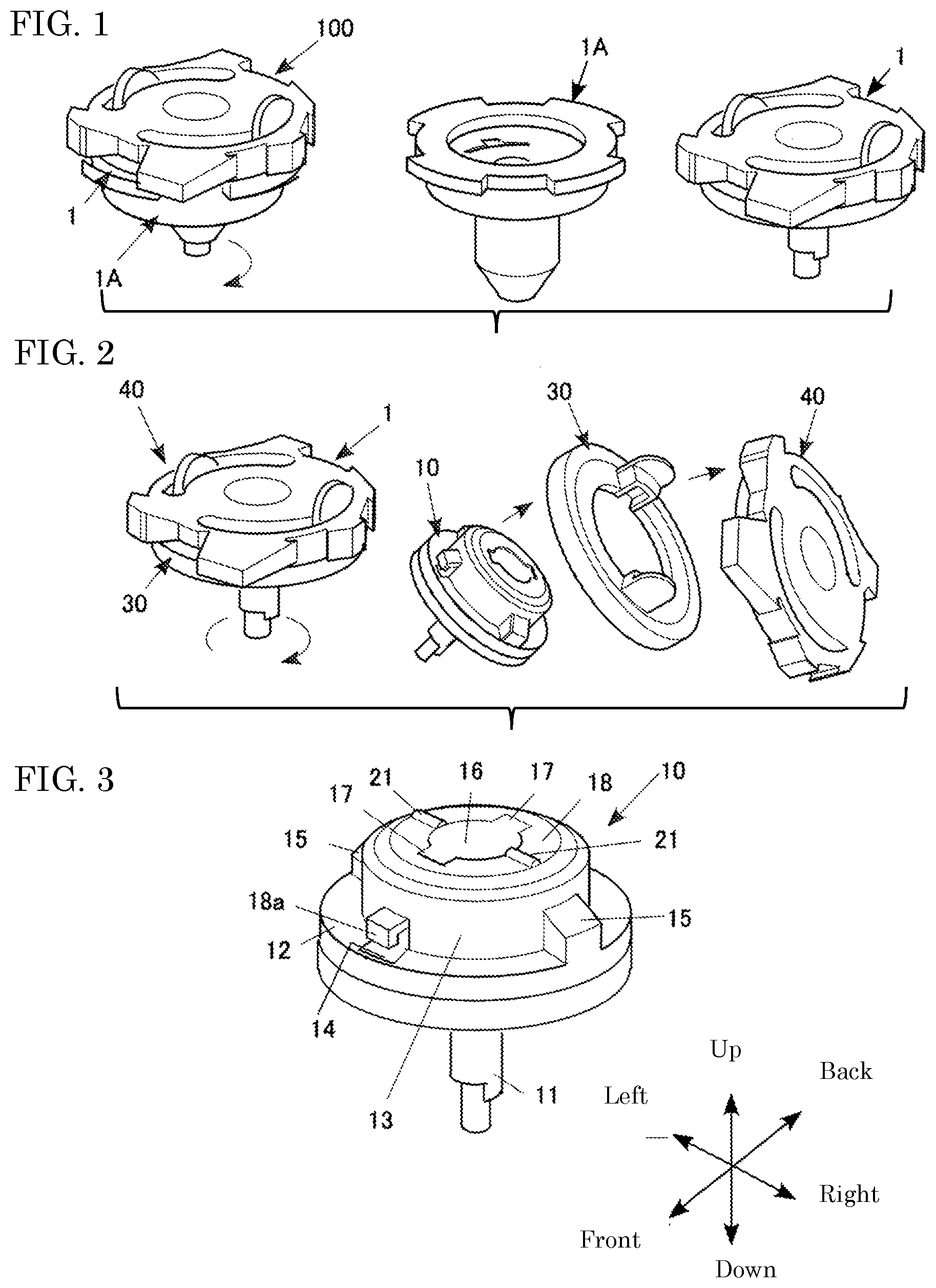
[0016] FIG. 1 is a perspective view showing the state of a first stage disassembly of the top toy of the present invention.
[0017] FIG. 2 is a perspective view showing the state of a second stage disassembly of the first top toy.
[0018] FIG. 3 is a perspective view showing a shaft part of the first top toy.
[0019] FIG. 4 is an exploded perspective view showing half of the shaft part of the first top toy.
[0020] FIG. 5 is an exploded perspective view showing half of the body and the variable performance ring of the first top toy.
[0021] FIG. 6 is a perspective view showing a second top toy.
[0022] FIG. 7 is a vertical cross section view showing half of the second top toy.
[0023] FIG. 8 is a perspective view showing an example of a launcher that rotationally drives the top toy.
[0024] FIG. 9 is a plan view showing the coupling structure of the first top toy and the second top toy.
DETAILED DESCRIPTION OF PREFERRED EMBODIMENTS
[0025] Following, the top toy of the present invention is explained based on an embodiment shown in the drawings.
[0026] FIG. 1 is a perspective view showing the state of the first stage disassembly of the top toy of the present embodiment.
[0027] FIG. 2 is a perspective view showing the state of the second stage disassembly of the top toy.
[0028] A top toy 100 of the embodiment is a combined type top toy that can be used in a so-called battle game. In specific terms, with this top toy 100, as shown in FIG. 1, by the impact force of colliding with each other, the top toy 100 is disassembled in a first stage into a first top toy 1 (hereafter called "top toy 1") and a second top toy 1A (an example of a lower part, hereafter called "top toy 1A"), and as shown in FIG. 2, the first top toy 1 is further disassembled in a second stage into disassembly elements.
[0029] It is also possible to use this top toy 1 alone. It is also possible for the top toy 1 and the second top toy 1A to continue spinning even after disassembly.
First Top Toy 1
[0030] As shown in FIG. 2, the top toy 1 comprises a shaft part 10 (an example of the upper part), a variable performance ring 30, and a body 40.
Detailed Configuration of Top Toy 1
1. Shaft Part 10
[0031] FIG. 3 is a perspective view showing the shaft part 10, and FIG. 4 is a cross section perspective view showing half of the shaft part 10. Here, only half is shown, but the remaining half has the same structure except for a rod-shaped shaft 11.
[0032] The shaft part 10 comprises the rod-shaped shaft 11 which is a grounding part, a flange 12 at the vertical direction middle part, and a cylindrical part 13 at the upper part. Of these, the flange 12 and the cylindrical part 13 are formed as an integral unit.
[0033] One hole 14 each is formed at front and back on the flange 12 and the cylindrical part 13. Also, one protruding part 15 each is formed at left and right on the cylindrical part 13. The outer surface of the protruding part 15 is flush with the outer circumference surface of the flange 12.
[0034] A cylindrical body 16 is placed inside the cylindrical part 13. The cylindrical body 16 is erected on a lower plate 101 attached below the flange 12. One claw 17 each is formed front and back on the upper end of this cylindrical body 16. The bottom surface of the claw 17 configures the downward facing surface. The rod-shaped shaft 11 is provided to be able to move vertically on the interior of the cylindrical body 16. Specifically, on the upper end part of the rod-shaped shaft 11, a long hole 11a that is long in the vertical direction is formed, and the rod-shaped shaft 11 is supported on the cylindrical body 16 by a pin 102 passed through the long hole 11a. This rod-shaped shaft 11 pierces through the lower plate 101 and extends to below the lower plate 101. The lower end part of the rod-shaped shaft 11 is a small diameter part 11b (a bottom part thereof is an example of the lower tip), and an engaging projection 11c is formed on the upper end part of the small diameter part 11b. This engaging projection 11c is an example of a first engaging part.
[0035] Also, the shaft part 10 comprises a cylindrical shaped pressing member 18. This pressing member 18 is installed to surround the outer circumference of the cylindrical body 16 on the inside of the cylindrical part 13. One leg part 18a each is provided at left and right on the outer circumference lower end part of the pressing member 18. The leg part 18a is inserted in the hole 14 formed over the flange 12 and the cylindrical part 13. Also, the pressing member 18 is energized upward by a coil spring 19. Also, the pressing member 18 has upward movement by the leg part 18a restricted by the top edge of the hole 14, and normally, the upper end of the pressing member 18 is at the same height position as the upper end of the cylindrical part 13. Also, one convex strip (protrusion) 21 each is formed extending in the radial direction left and right on the top surface of the ceiling part of the pressing member 18.
2. Variable Performance Ring 30
[0036] FIG. 5 is a cross section perspective view showing half of the variable performance ring 30 and the body 40. Here, only half is shown, but the remaining half also has the same structure except for the identification component 60.
[0037] With this embodiment, a flywheel is used as the variable performance ring 30. This variable performance ring 30 has a plate shape. An annular step part 31 that can house the flange 12 of the shaft part 10 from below is formed on the bottom surface of this variable performance ring 30. Also, one protruding part 32 protruding facing upward at left and right each is formed on the top surface of this variable performance ring 30. A concave part 33 that can house the protruding part 15 of the shaft part 10 from below is formed on the lower part of each protruding part 32. Also, a tongue piece 34 extending upward just outside of each protruding part 32 is formed on the top surface of the variable performance ring 30.
[0038] As this variable performance ring 30, instead of the flywheel, or being integrally formed with the flywheel, this can be an item that has a protruding part on the outer circumference surface and makes it easy to attack the top toy of the other party, or an item that has a concave part on the outer circumference surface and is less susceptible to attacks from the top toy of the other party.
3. Body 40
[0039] As shown in FIG. 5, unevenness 40a is formed on the outer circumference of the body 40. Also, an annular recess 42 that can house the protruding part 32 of the variable performance ring 30 from below is formed on the bottom surface of the body 40. One claw 44 that protrudes facing radially inward each is provided protruding at front and back at the inner circumference surface lower end of an inner peripheral wall 43a that partitions and forms this annular recess 42.
[0040] Also, one protrusion 47 that protrudes facing radially inward at left and right each is provided protruding at the vertical direction middle part of the inner circumference surface of the inner peripheral wall 43a.
[0041] Furthermore, a corrugated part 45 that meshes with the convex strip 21 for which unevenness is continuously formed in the lateral direction is formed on the lower end surface of the inner peripheral wall 43a.
[0042] Also, an arc shaped slit 46 in which can be inserted from below each tongue piece 34 of the variable performance ring 30 is formed on a ceiling wall 43b that partitions and forms the annular recess 42 of the body 40. The length of this arc shaped slit 46 is long enough for the tongue piece 34 to be able to move. Also, one end part of the arc shaped slit 46 is a narrow width so that a claw 54b of a launcher 50 described later engages with the edge bottom.
4. Assembly Method for Top Toy 1
[0043] Next, an example of an assembly method of the top toy 1 is explained.
[0044] First, the protruding part 15 of the shaft part 10 is matched with the concave part 33 of the variable performance ring 30 from below, and the shaft part 10 and the variable performance ring 30 are assembled in a fitted state.
[0045] Next, this assembled body approaches the body 40 from below. At this time, the tongue piece 34 of the variable performance ring 30 of the assembled body is matched to a prescribed end of the arc shaped slit 46 of the body 40. This state is a state in which the claw 17 of the shaft part 10 and the claw 44 of the body 40 do not overlap in the vertical direction. This state is the coupling release state.
[0046] After that, the shaft part 10 of the assembled body is pressed to the body 40 side. Having done that, first, the variable performance ring 30 is pressed against the bottom surface of the body 40. Furthermore, the coil spring 19 shrinks, and the claw 17 of the shaft part 10 is pushed up relatively upward compared to the claw 44 of the body 40.
[0047] Also, the shaft part 10 is rotated integrally with the variable performance ring 30 with respect to the body 40 until the tongue piece 34 moves to the end of the side opposite to the prescribed end noted above. Having done that, the claw 17 of the shaft part 10 and the claw 44 of the body 40 are in a state overlapping vertically. Also, the state in which the bottom surface of the claw 17 of the shaft part 10 and the top surface of the claw 44 of the body 40 have abutted, in which when the hand lets go of the shaft part 10, by the energizing force of the coil spring 19, the bottom surface of the claw 17 of the shaft part 10 and the top surface of the claw 44 of the body 40 abut, is the coupled state. By doing this, the shaft part 10, the variable performance ring 30, and the body 40 are coupled, and the top toy 1 is assembled.
Configuration of Top Toy 1A
1. Overall
[0048] FIG. 6 is a perspective view showing the top toy 1A. FIG. 7 is a cross section perspective view showing half of the top toy 1A. Here, only half is shown, but the remaining half also has the same structure except for a coil spring 114.
[0049] The top toy 1A comprises a tubular shaft 110 and a body 150 (an example of the lower part main body). The tubular shaft 110 is provided to be able to move vertically with respect to the body 150.
2. Body 150
[0050] The body 150 is substantially a disk shape, and a round concave part 151 concentric with the axis center is formed on the top surface. The lower plate 101 of the shaft part 10 is seated on this round concave part 151. On the floor of the round concave part 151 is formed a round hole 152 that is concentric with the axis center at the center. The rod-shaped shaft 11 is inserted through this round hole 152 from above. Also, on the floor of the round concave part 151, one arc shaped hole 153 each is formed concentrically with the axis center at two locations sandwiching and facing the round hole 152. On the arc shaped hole 153 is formed a notch 153a that expands radially outward at the circumference direction middle part.
[0051] The bottom surface of the body 150 is an inclined surface of an inverted cone shape so as to gradually have the diameter decrease facing downward. At the bottom surface of the body 150, a round hole 154 connecting with the abovementioned round hole 152 is formed concentrically with the axis center at the center. The tubular shaft 110 is inserted in this round hole 154.
3. Tubular Shaft 110
[0052] The tubular shaft 110 is formed in a substantially cylindrical shape overall. The bottom surface of the tubular shaft 110 is formed in an inverted cone shape. A round hole 111 that is concentric with the axis center as the center is formed on the bottom surface of the tubular shaft 110. The small diameter part 11b of the rod-shaped shaft 11 is inserted from above in this round hole 111. Also, as shown in the enlarged view of FIG. 7, at the bottom wall of the tubular shaft 110, an engaging recess 112 that can engage with the abovementioned engaging projection 11c is formed on the top surface. This engaging recess 112 is an example of a second engaging part.
[0053] The upper half of the tubular shaft 110 forms two arch shaped walls 110b, 110b partitioned by two slits 110a, 110a extending in the vertical direction. Each arch shaped wall 110b is inserted from below in the corresponding arc shaped hole 153. Also, at the circumferential direction middle part of each arc shaped wall 110b, a protrusion 110c (FIG. 9) is formed at the upper end outside. The bottom surface of the protrusion 110c configures the downward facing surface. Each protrusion 110c is inserted from below in the corresponding notch 153a.
[0054] This makes it possible for the tubular shaft 110 to move vertically with respect to the body 150.
[0055] Though not illustrated, a flange is formed on the outer circumference on the tubular shaft 110, and meanwhile, on the body 150, attached is a dropout stopping prevention member that supports that flange from below to prevent dropping out.
[0056] Also, the coil spring 114 is provided inside the tubular shaft 110. The coil spring 114 is arranged between the top surface of the bottom wall of the tubular shaft 110 and the upper wall of the round hole 154, energizing the tubular shaft 110 downward.
Coupling of Top Toy 1 and Top Toy 1A
[0057] The top toy 1 and the top toy 1A are matched to each other from the vertical direction, and the rod-shaped shaft 11 and the round hole 152 are made to be matched, and the shaft part 10 of the top toy 1, that is, the lower plate 101, is seated on the round concave part 151. At this time, the rod-shaped shaft 11 is in a dropped position, but does not protrude from the lower end of the tubular shaft 110.
[0058] Next, the tubular shaft 110 is strongly pushed by hand into the body 150 against the energizing force of the coil spring 114. By doing this, the tubular shaft 110 moves up with respect to the body of the top toy 1A (body 150), and the protrusion 110c is engaged with the top surface of a convex part 101b of the top toy 1 side. The part for which the top part top surface of the convex part 101b is formed has elasticity. The top surface of this convex part 101b configures the upward facing surface. Also, by the tubular shaft 110 moving up, the engaging projection 11c and the engaging recess 112 are engaged. By doing this, the relative rotation of the shaft part 10 of the top toy 1 and the top toy 1A becomes impossible. Meanwhile, the engagement of the engaging projection 11c and the engaging recess 112 is released when the rod-shaped shaft 11 touches ground. By doing this, the relative rotation of the shaft part 10 of the top toy 1 and the top toy 1A becomes possible.
[0059] As shown in FIG. 9, in specific terms, the convex part 101b is formed at the circumference direction middle of a groove 101a extending in the vertical direction of the lower plate 101. The engagement of the engaging projection 11c and the engaging recess 112 is released when the shaft part 10 of the top toy 1 and the top toy 1A perform relative rotation, and the tubular shaft 110 protrudes downward relative to the top toy 1A by the energizing force of the coil spring 114.
How to Play
[0060] Following, the method of using this top toy 100 is explained.
[0061] The charge of the rotational force of the top toy 100 in this case is performed by the launcher 50 such as that shown in FIG. 8. This launcher 50 is a mechanism for rotation of a top holder 53 when a handle 51 is pulled.
[0062] A fork 54 is formed on this top holder 53, this fork 54 is plugged into the arc shaped slit 46 of the body 40, and the claw 54b is engaged with the edge bottom of the arc shaped slit 46. Then, when the handle 51 of the launcher 50 is pulled all the way, while rotation of the round disk and thus the top holder 53 is stopped, the top toy 1 still rotates due to inertial force, so the top toy 1 follows the inclined surface 54a of the fork 54 and separates from the top holder 53.
[0063] The top toy 100 shot in this way is rotated in a prescribed field, and when it collides with the other party's top toy 100, due to impact force or rubbing, etc., due to the collision force, a force (external impact) in the direction opposite to the rotation force of the shaft part 10 and the variable performance ring 30 acts on the body 40. By doing this, the first top toy 1 and the top toy 1A are disassembled (first stage disassembly). After the first stage disassembly as well, the top toy 1 and the top toy 1A continue to spin. Then, when the external impact acts on the body 40 of the top toy 1, the body 40 performs relative rotation in the direction opposite to the rotation direction of the shaft part 10 and the variable performance ring 30. Having done this, the convex strip 21 meshes with the corrugated part 45 of the body 40, and the energizing force of the coil spring 19 acts on the convex strip 21, so with each acting of the impact force due to collision, when the coupling release position is reached by changing the meshing position by performing relative rotation of the shaft part 10 with respect to the body 40, the claw 44 of the body 40 separates from the claw 17 of the shaft part 10, so the body 40 breaks away from the shaft part 10 due to the energizing force of the coil spring 19 (second stage disassembly). Then, in FIG. 1, as shown at the right side, the top toy 1 is disassembled.
Modification Examples of the Present Embodiment
[0064] Above, an embodiment of the present invention was explained, but the present invention is not limited to this embodiment, and it goes without saying that various modifications are possible within a range that does not stray from the gist of the invention.
[0065] For example, with the abovementioned embodiment, a case was shown with the upper part being the shaft part 10 of the first top toy 1, and the lower part being the second top toy 1A, but as long as it is a part for which a rod-shaped shaft is provided on the upper part, it is also possible to apply this to one top toy.
[0066] Also, with the abovementioned embodiment, an example was explained of the rod-shaped shaft 11 dropping by its own weight, but it is also possible to be dropped by energization by a spring. Working in this way, it is possible to suppress relative rotation even in a state when the top toy 100 is not upright.
[0067] Furthermore, with the abovementioned embodiment, the engaging projection 11c of the rod-shaped shaft 11 was engaged in the engaging recess 112 of the tubular shaft 110, but it is also possible to engage the engaging projection 11c in the body 150.
[0068] With the first engaging part and the second engaging part, when the rod-shaped shaft is ungrounded, the first engaging part and the second engaging part engage, blocking relative rotation of the upper part and the lower part, so it is possible to suppress unintended disassembly of the upper part and the lower part. Meanwhile, when the rod-shaped shaft touches ground, the rod-shaped shaft moves up and the engagement of the first engaging part and the second engaging part is automatically released, making it possible to enjoy desired play.
[0069] When the upper part and the lower part are coupled, the spring stores energy, so when the abutment of the upward facing surface of the upper part and the downward facing surface of the lower part is released, it is possible to fly the upper part.
[0070] It is possible to suppress unintended disassembly of the first top toy and the second top toy.
[0071] Disassembly of the first top toy and the second top toy can be performed easily.
[0072] The above and/or other aspects, features and/or advantages of various embodiments will be further appreciated in view of the following description in conjunction with the accompanying figures. Various embodiments can include and/or exclude different aspects, features and/or advantages where applicable. In addition, various embodiments can combine one or more aspect or feature of other embodiments where applicable. The descriptions of aspects, features and/or advantages of particular embodiments should not be construed as limiting other embodiments or the claims. In the drawings, the size and relative sizes of layers and regions may be exaggerated for clarity. Like numbers refer to like elements throughout. The terminology used herein is for the purpose of describing particular embodiments only and is not intended to be limiting of the invention. As used herein, the singular forms "a", "an" and "the" are intended to include the plural forms as well, unless the context clearly indicates otherwise. As used herein, the term "and/or" includes any and all combinations of one or more of the associated listed items and may be abbreviated as "/". It will be understood that, although the terms first, second, etc. may be used herein to describe various elements, these elements should not be limited by these terms. Unless indicated otherwise, these terms are only used to distinguish one element from another. For example, a first object could be termed a second object, and, similarly, a second object could be termed a first object without departing from the teachings of the disclosure. It will be further understood that the terms "comprises" and/or "comprising," or "includes" and/or "including" when used in this specification, specify the presence of stated features, regions, integers, steps, operations, elements, and/or components, but do not preclude the presence or addition of one or more other features, regions, integers, steps, operations, elements, components, and/or groups thereof. It will be understood that when an element is referred to as being "connected" or "coupled" to or "on" another element, it can be directly connected or coupled to or on the other element or intervening elements may be present. In contrast, when an element is referred to as being "directly connected" or "directly coupled" to another element, there are no intervening elements present. Other words used to describe the relationship between elements should be interpreted in a like fashion (e.g., "between" versus "directly between," "adjacent" versus "directly adjacent," etc.). However, the term "contact," as used herein refers to direct contact (i.e., touching) unless the context indicates otherwise. Terms such as "same," "planar," or "coplanar," as used herein when referring to orientation, layout, location, shapes, sizes, amounts, or other measures do not necessarily mean an exactly identical orientation, layout, location, shape, size, amount, or other measure, but are intended to encompass nearly identical orientation, layout, location, shapes, sizes, amounts, or other measures within acceptable variations that may occur, for example, due to manufacturing processes. The term "substantially" may be used herein to reflect this meaning. Unless otherwise defined, all terms (including technical and scientific terms) used herein have the same meaning as commonly understood by one of ordinary skill in the art to which this disclosure belongs. It will be further understood that terms, such as those defined in commonly used dictionaries, should be interpreted as having a meaning that is consistent with their meaning in the context of the relevant art and/or the present application, and will not be interpreted in an idealized or overly formal sense unless expressly so defined herein.
* * * * *
D00000
D00001
D00002
D00003
D00004
XML
uspto.report is an independent third-party trademark research tool that is not affiliated, endorsed, or sponsored by the United States Patent and Trademark Office (USPTO) or any other governmental organization. The information provided by uspto.report is based on publicly available data at the time of writing and is intended for informational purposes only.
While we strive to provide accurate and up-to-date information, we do not guarantee the accuracy, completeness, reliability, or suitability of the information displayed on this site. The use of this site is at your own risk. Any reliance you place on such information is therefore strictly at your own risk.
All official trademark data, including owner information, should be verified by visiting the official USPTO website at www.uspto.gov. This site is not intended to replace professional legal advice and should not be used as a substitute for consulting with a legal professional who is knowledgeable about trademark law.