Clear Mat For Layered Borderless Frames And Methods Of Making
Doherty; Morgan ; et al.
U.S. patent application number 16/797878 was filed with the patent office on 2020-08-27 for clear mat for layered borderless frames and methods of making. This patent application is currently assigned to Wexel Art. The applicant listed for this patent is Wexel Art. Invention is credited to Morgan Doherty, Natasha McRee.
| Application Number | 20200268179 16/797878 |
| Document ID | / |
| Family ID | 1000004704720 |
| Filed Date | 2020-08-27 |


| United States Patent Application | 20200268179 |
| Kind Code | A1 |
| Doherty; Morgan ; et al. | August 27, 2020 |
CLEAR MAT FOR LAYERED BORDERLESS FRAMES AND METHODS OF MAKING
Abstract
A clear mat is formed from a transparent or translucent machinable material and has an opening dimensioned to receive an article. The clear mat is sized to precisely match the width and height of a borderless frame. The borderless frame has a front panel and a back panel and is also made of a transparent or translucent machinable material. The opening of the clear mat has a thickness ranging from about 1/16 to about two inches. The clear mat is sandwiched between the front and back panels of the borderless frame with the article held in the opening without having to touch the front panel. The clear mat can prevent dust or foreign elements to come in contact with the article. The borderless frame with the clear mat can be mounted on a wall using mounting hardware through aligned holes in the clear mat and the front and back panels.
| Inventors: | Doherty; Morgan; (Austin, TX) ; McRee; Natasha; (Austin, TX) | ||||||||||
| Applicant: |
|
||||||||||
|---|---|---|---|---|---|---|---|---|---|---|---|
| Assignee: | Wexel Art |
||||||||||
| Family ID: | 1000004704720 | ||||||||||
| Appl. No.: | 16/797878 | ||||||||||
| Filed: | February 21, 2020 |
Related U.S. Patent Documents
| Application Number | Filing Date | Patent Number | ||
|---|---|---|---|---|
| 62809322 | Feb 22, 2019 | |||
| Current U.S. Class: | 1/1 |
| Current CPC Class: | A47G 1/0638 20130101 |
| International Class: | A47G 1/06 20060101 A47G001/06 |
Claims
1. A clear mat, comprising: a body formed from a transparent or translucent machinable material, the body having an interior opening, four edges, and corner holes, the four edges machined to precisely match edges of a front panel and a back panel of a borderless frame, the borderless frame made of the transparent or translucent machinable material, the corner holes sized to receive mounting hardware therethrough and positioned in alignment with corner holes in the front panel and the back panel of the borderless frame, the interior opening having a width, a height, and a depth to accommodate an article such that, when placed in the interior opening of the clear mat between the front panel and the pack panel of the borderless frame, the article is substantially free from contacting the front panel of the borderless frame.
2. The clear mat of claim 1, wherein the depth of the interior opening is in a range of about 1/16 of an inch to about two inches.
3. The clear mat of claim 1, wherein the transparent or translucent machinable material comprises glass, clear acrylic, clear plastic, polymethyl methacrylate, or thermoplastic.
4. The clear mat of claim 1, wherein the interior opening has a boxy shape, a circular shape, or a free form.
5. The clear mat of claim 1, wherein the article is thicker than a flat sheet of paper or film.
6. The clear mat of claim 1, wherein the article is a record album, a compact disc, textile, a book, a rug, a comic book, a photograph, a piece of art, a calendar, or a puzzle.
7. The clear mat of claim 1, further comprising: a plurality of holes positioned along the four edges.
8. A borderless frame, comprising: a front panel having four edges and corner holes; a back panel having four edges and corner holes; and a clear mat having an interior opening, four edges, and corner holes; wherein the front panel, the back panel, and the clear mat are formed from a transparent or translucent machinable material; wherein the four edges of the clear mat are machined to precisely match the four edges of the front panel and of the back panel; wherein the corner holes of the clear mat are sized to receive mounting hardware therethrough and positioned in alignment with the corner holes in the front panel and the back panel; and wherein the interior opening of the clear mat has a width, a height, and a depth to accommodate an article such that, when placed in the interior opening of the clear mat between the front panel and the pack panel, the article is substantially free from contacting the front panel.
9. The borderless frame of claim 8, wherein the depth of the interior opening of the clear mat is in a range of about 1/16 of an inch to about two inches.
10. The borderless frame of claim 8, wherein the transparent or translucent machinable material comprises glass, clear acrylic, clear plastic, polymethyl methacrylate, or thermoplastic.
11. The borderless frame of claim 8, wherein the interior opening has a boxy shape, a circular shape, or a free form.
12. The borderless frame of claim 8, wherein the article is thicker than a flat sheet of paper or film.
13. The borderless frame of claim 8, wherein the article is a record album, a compact disc, textile, a book, a rug, a comic book, a photograph, a piece of art, a calendar, or a puzzle.
14. The borderless frame of claim 8, wherein each of the clear mat, the front panel, and the back panel further comprises: a plurality of holes positioned along the four edges.
15. A method of making the clear mat of claim 1, the method comprising: determining a size of the borderless frame; determining dimensions of the article; determining a size of the mounting hardware; programming a precision cutting machine with a plurality of input parameters, the plurality of input parameters including a first input parameter for the four edges based on the size of the borderless frame, a second input parameter for the interior opening based on the dimensions of the article, and a third input parameter for the corner holes based on the size of mounting hardware; and operating the precision cutting machine on the transparent or translucent machinable material to form the clear mat of claim 1.
16. The method according to claim 15, further comprising: creating a project with the plurality of input parameters, wherein the operating further comprises executing the project.
17. The method according to claim 15, wherein the precision cutting machine is a laser cutter or a computer numerical control router.
18. A method of using the clear mat of claim 1, the method comprising: securing two corners of the back panel, the clear mat, and the front panel together using a first pair of the mounting hardware through two of the corner holes, leaving one side of the borderless frame open for access; placing the article in the interior opening of the clear mat between the front panel and the back panel; and securing remaining two corners of the back panel, the clear mat, and the front panel together using a second pair of the mounting hardware through remaining two of the corner holes.
19. The method according to claim 18, further comprising: removing the second pair of the mounting hardware from the borderless frame; lifting the front panel; and retrieving the article from the interior opening of the clear mat.
20. The method according to claim 19, further comprising: placing the article back to the interior opening of the clear mat; and reinstalling the second pair of the mounting hardware to secure the article in the interior opening of the clear mat between the front panel and the back panel of the borderless frame.
Description
CROSS-REFERENCE TO RELATED APPLICATION(S)
[0001] This is a conversion of, and claims a benefit of priority under 35 U.S.C. .sctn. 119(e) from, U.S. Provisional Application No. 62/809,322, filed Feb. 22, 2019, entitled "CLEAR MAT FOR LAYERED BORDERLESS FRAMES AND METHODS OF MAKING," which is fully incorporated by reference herein for all purposes. This application relates to U.S. patent application Ser. No. 29/681,199, filed Feb. 22, 2019, entitled "CLEAR MAT," which is also fully incorporated by reference herein for all purposes.
TECHNICAL FIELD
[0002] This disclosure relates generally to picture frames. More particularly, this disclosure relates to borderless frames. Even more particularly, embodiments disclosed herein relate to a clear mat useful for double-panel or multi-layer framing of three-dimensional books, art, and textiles.
BACKGROUND OF THE RELATED ART
[0003] A picture frame is a physical structure that encloses and displays a generally planar or flat article. A mat is a sheet of material usually placed around the article as a border to hold the article in place so that the article can be observed or otherwise seen through a viewing window of the picture frame. Different styles of picture frames can be found in U.S. Pat. Nos. 5,960,573, 6,460,280, 6,865,837, 7,412,792, 8,365,452, and 9,380,892.
[0004] One of the many styles of picture frames is referred to as "Borderless frames." Borderless frames are usually made from an entirely glass, acrylic, or similarly clear or translucent material, giving a frameless look when used.
[0005] With borderless frames, pictures are generally mounted between transparent panels, which protect pictures from the front and the back. The panel in the front is generally referred to as the glazing panel. The panel in the back is generally referred to as the backing or backer panel. Examples of different kinds of borderless frames can be found in EP2222209B9 and GB2450379A.
SUMMARY OF THE DISCLOSURE
[0006] Embodiments disclosed herein provide a new approach to structure clear acrylic, glass, or other clear, transparent, or translucent machinable materials for borderless framing and signage. This new approach is realized in a unique clear mat for borderless frames, making them useful for framing more challenging articles and meeting conservational requirements.
[0007] In some embodiments, a clear mat can be formed of a clear or translucent material and cut to perfectly match the outer layer panels (e.g., a front panel and a back panel), keeping the "frameless" look that is desired. Holes may be formed to match any mechanical or mounting hardware that must pass through the clear mat to hold the framed package together.
[0008] The interior of the clear mat can be formed to exactly match the border of the article or object (e.g., a piece of art or textile) to be held or otherwise contained there-within. This serves a dual-purpose--it serves to support the weight of the framed object, allowing for the possibility of not having to adhere the object to the back panel. It may also allow the object to appear to float between layers without visible mounting techniques such as sewing, taping or gluing.
[0009] The clear mat can be formed in a thinner or thicker profile as needed. Optionally, it can be glued or using any appropriate adhesion method to create a bonded set of panels that will not allow air to pass through. To save cost and reduce weight, mats can be formed with very thin profiles that are glued or bonded only around the edges of either or both panels, and/or only around the edges of the art. In some embodiments, the clear mat can be tightly sandwiched between the panels but is not bonded or glued to any panel.
[0010] These, and other, aspects of the disclosure will be better appreciated and understood when considered in conjunction with the following description and the accompanying drawings. It should be understood, however, that the following description, while indicating various embodiments of the disclosure and numerous specific details thereof, is given by way of illustration and not of limitation. Many substitutions, modifications, additions, and/or rearrangements may be made within the scope of the disclosure without departing from the spirit thereof, and the disclosure includes all such substitutions, modifications, additions, and/or rearrangements.
BRIEF DESCRIPTION OF THE DRAWINGS
[0011] The drawings accompanying and forming part of this specification are included to depict certain aspects of the invention. A clearer impression of the invention, and of the components and operation of systems provided with the invention, will become more readily apparent by referring to the exemplary, and therefore non-limiting, embodiments illustrated in the drawings, wherein identical reference numerals designate the same components. Note that the features illustrated in the drawings are not necessarily drawn to scale.
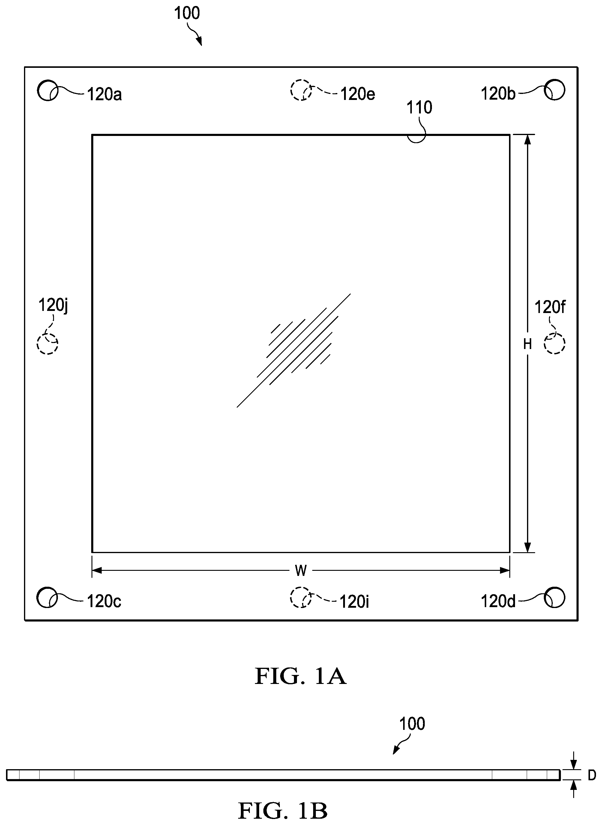
[0012] FIG. 1A depicts a diagrammatic representation of an example of a clear mat according to some embodiments.
[0013] FIG. 1B depicts a profile view of the clear mat shown in
[0014] FIG. 1A.
[0015] FIG. 2A depicts a diagrammatic representation of an example of a clear mat in use with a borderless frame.
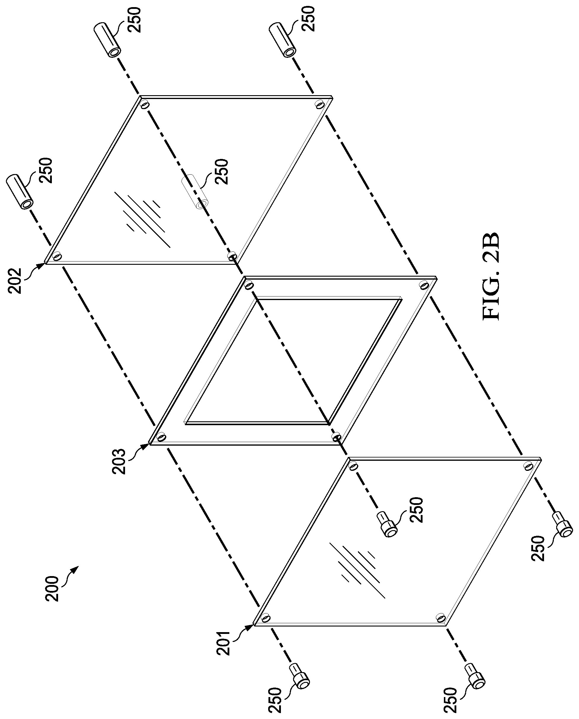
[0016] FIG. 2B depicts an exploded view of the borderless frame with the clear mat shown in FIG. 2A.
[0017] FIG. 3A depicts a diagrammatic representation of another example of a clear mat according to some embodiments.
[0018] FIG. 3B depicts the clear mat of FIG. 3A in use with a borderless frame.
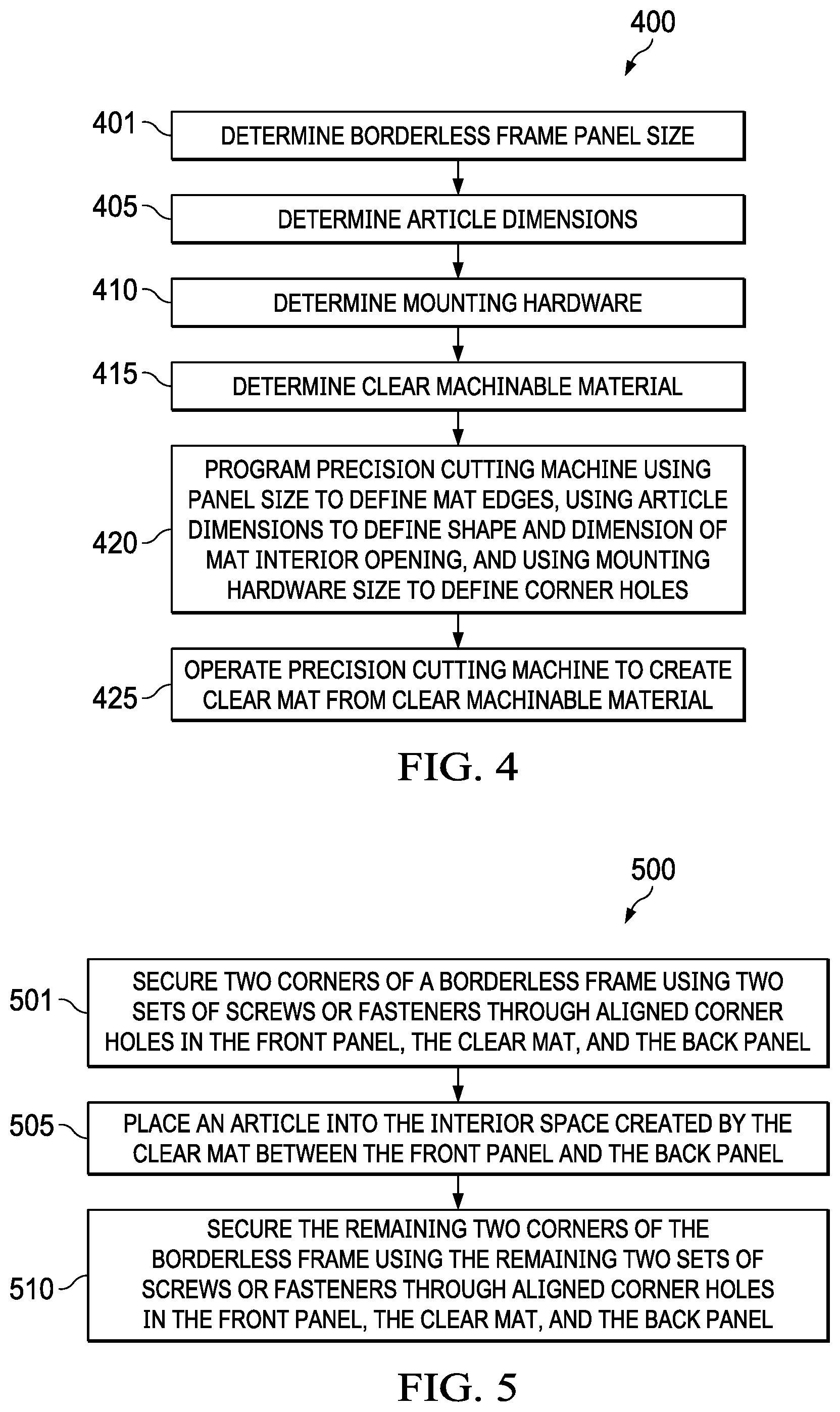
[0019] FIG. 4 is a flow chart illustrating an example of a method of making a clear mat disclosed herein.
[0020] FIG. 5 is a flow chart illustrating an example of mounting a borderless frame with a clear mat disclosed herein.
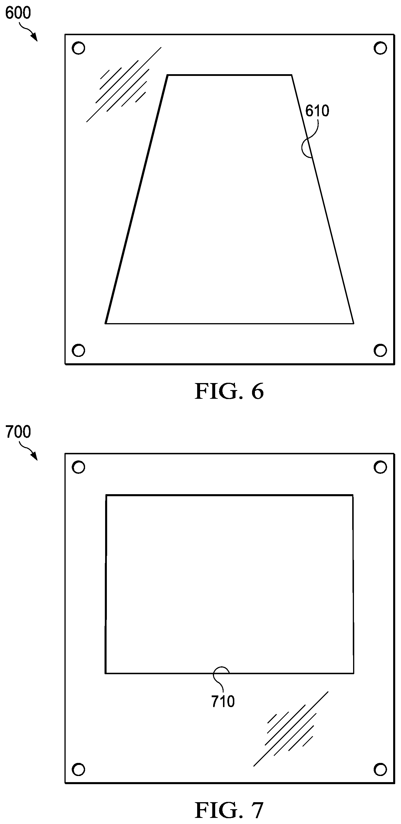
[0021] FIGS. 6-8 depict diagrammatic representations of examples of a clear mat having a custom opening according to some embodiments.
DETAILED DESCRIPTION
[0022] The invention and the various features and advantageous details thereof are explained more fully with reference to the non-limiting embodiments that are illustrated in the accompanying drawings and detailed in the following description. Descriptions of well-known starting materials, processing techniques, components, and equipment are omitted so as not to unnecessarily obscure the invention in detail. It should be understood, however, that the detailed description and the specific examples, while indicating some embodiments of the invention, are given by way of illustration only and not by way of limitation. Various substitutions, modifications, additions, and/or rearrangements within the spirit and/or scope of the underlying inventive concept will become apparent to those skilled in the art from this disclosure.
[0023] Several challenges exist for making and using borderless frames. For instance, for reasons of conservation, fine arts should not be pressed flat against the glazing panel because they may become stuck together over time. This conservation principle applies whenever an article is at risk of adhering to the surface of the glazing panel over time (e.g., due to humidity in the environment where the article is displayed).
[0024] To prevent an accidental adhesion between the article and the glazing panel, a gap between the glazing panel and the article is needed to allow the glazing panel to "float" above and does not touch the article. However, such a gap is not desirable for a borderless frame as the gap can make the article less secure, and can allow dust and other elements (e.g., insects, hair, fiber, etc.) to easily enter between the glazing and backing panels. Thus, conventional borderless frames generally are not suitable for use in displaying fine art or any article that cannot or should not have direct contact with the glazing panel.
[0025] Another challenge relates to the type of articles that a borderless frame can accommodate. Because a borderless frame is usually made of two panels, they are ideal for holding generally planar (flat) articles such as a flat sheet of paper, picture, or photograph. However, art and textiles are often thicker than a flat sheet of paper. As such, when an article that is thicker than a flat sheet of paper or film is placed between the glazing panel and the backing panel, the article (e.g., a record album, a CD, a rug, a piece of textile, a piece of art such as a three-dimensional art, an oil painting, etc.) will create a gap between the panels. Again, such a gap is not desirable for a borderless frame as the gap allows dust and other elements to easily enter between the glazing and backing panels and accumulate on and/or stick to the article. For these reasons, borderless frames are generally not suitable for showcasing non-planar articles.
[0026] Further, while existing methods of matting have been developed for traditional picture framing, for instance, with opaque moulding, opaque matting, opaque backing, etc., the same cannot be said for borderless framing. Indeed, in the more contemporary style of clear and frameless framing, fewer solutions exist that solve the aforementioned conservational problem of not allowing an article to come in contact with the glazing panel when the article is mounted between the two clear panels.
[0027] A prior approach uses spacers around the mounting hardware to create a gap between the two clear panels. This approach does not solve the problem in that the gap thus created by the spacers also creates a void that allows dust and other elements to enter in between the two clear panels and settle on and/or stick to the article.
[0028] The same technique may be used to intentionally create a gap between two panels when a borderless frame is used to frame thicker articles. However, an additional challenge exists due to the weight of a thicker article. The heavier an article is, the harder it can be for a borderless frame to support the article because there is less friction between the glazing and backing panels of the borderless frame.
[0029] Another prior approach uses clear or translucent moulding where a rebate (or rabbet, which is a recess or groove cut into the edge of a piece of machinable material) is routed into a thicker slab of acrylic, and glazing is dropped into the rebate much like traditional framing.
[0030] Yet another approach uses five-sided clear shadowboxes mounted over a backer substrate to create a case around three dimensional objects.
[0031] However, these approaches can be expensive, difficult to make, and the resulting display apparatuses do not have the same appearance of a clear borderless, frameless frame in which an article held by the frame seems to be floating or suspended in air.
[0032] In view of the challenges for clear borderless frames and the drawbacks of prior approaches, embodiments disclosed herein provide a new approach to structure clear acrylic, glass, or other clear, transparent, or translucent machinable materials for borderless framing and signage.
[0033] As alluded to above, this new approach is realized in a unique clear mat for borderless frames, making them useful for framing more challenging articles and meeting conservational requirements. Various embodiments of the clear mat and methods of making and using the clear mat will now be described with references to the drawings.
[0034] FIG. 1A depicts a diagrammatic representation of a clear mat 100. As illustrated in FIG. 1A, clear mat 100 can have four edges, four corners, an interior opening 110, and four or more corner holes 120a, 120b, 120c, and 120d. Additional holes (e.g., 120e, 120f, 120i, 120j) can be positioned between 120a, 120b, between 120b, 120d, between 120c, 120d, or between 120a, 120c, as shown in FIG. 1A.
[0035] Alternatively or additionally, any number of holes in the perimeter of clear mat 100 can be added. Clear mat 100 can be formed from a single sheet, piece, or slab of clear, transparent, or translucent durable machinable material, such as poly(methyl methacrylate) (PMMA) (e.g., acrylic, Plexiglas.RTM., etc.), glass, or any transparent thermoplastic, and so on.
[0036] Interior opening 110 is dimensioned to receive or otherwise accommodate an article (e.g., a book, a comic book, a photograph, a certificate, an award, etc.). In the example of FIGS. 1A and 1B, the dimensions of interior opening 110 can be defined by a height (H), a width (W), and a depth (D).
[0037] FIG. 2A depicts a diagrammatic representation of an example of a clear mat 203 sandwiched between a front panel 201 and a back panel 202 of a borderless frame 200. In the example of FIG. 2A, borderless frame 200 is mounted to wall 280 through corner holes 220 and a set of four mounting screws 250.
[0038] As illustrated in FIG. 2A, an interior opening 210 of clear mat 203 creates an interior space between front panel 201 and back panel 202, allowing borderless frame 200 to hold an article, while the body of clear mat 203 is tightly coupled to front panel 201 and back panel 202 without leaving any space or gap that might allow dust, insects, or other particles to settle on or come in contact with the article.
[0039] In some embodiments, the interior space created by interior opening 210 of clear mat 203 can have a thickness ranging from approximately 1/16 inch to 2-inch without risking the article getting stuck to front panel 301 over time or allowing dust to settle on the article. This thickness allows the article to be positioned in interior opening 210 of clear mat 203 without having to come in contact with front panel 201, making borderless frame 200 useful for conservational purposes.
[0040] FIG. 2B depicts an exploded view of the borderless frame with the clear mat shown in FIG. 2A. As illustrated in FIGS. 2A-2B, front panel 201, back panel 202, and clear mat 203 are all made of a clear material, allowing the article to appear as if it is floating or suspended in air without any border or frame.
[0041] FIG. 3A depicts a diagrammatic representation of another example of a clear mat 300 according to some embodiments. Similar to clear mat 100 and clear mat 203 described above, clear mat 300 has four corner holes 320 sized to accommodate fasteners or mounting hardware.
[0042] In the example of FIG. 3A, clear mat 303 can have an interior opening 310 that is dimensioned to receive or otherwise to accommodate an article having a circular shape and a profile thicker than a sheet of paper (e.g., a record, a CD, etc.). According to embodiments disclosed herein, the shape and dimensions of an interior opening of a clear mat can be defined by the shape and dimensions of an article for which the clear mat is made to accommodate.
[0043] As a non-limiting example, an article can have a thickness in the range of about 1/16 of an inch to about two inches. Accordingly, the interior opening of a clear mat disclosed herein can have a depth that accommodates thicknesses in the range of about 1/16 inch to about two inches.
[0044] FIG. 3B depicts clear mat 300 sandwiched between a front panel 301 and a back panel 302 of a borderless frame 330. Each of front panel 301, back panel 302, and clear mat 300 has four corner holes 320 sized to accommodate mounting hardware 350. AS shown in FIG. 3B, corner holes 320 are positioned on each of front panel 301, back panel 302, and clear mat 300 has four corner holes 320 so that they are aligned. The interior opening of clear mat 300 is dimensioned to accommodate an article 390 (e.g., a phonograph record), leaving no gap around the perimeters of borderless frame 330. Since front panel 301, back panel 302, and clear mat 300 are all made of a clear, transparent material, when borderless frame 330 is mounted on a wall, article 390 would appear to float in front of the wall.
[0045] In some embodiments, the four edges of the clear mat disclosed herein are machined to precisely match the edges of a front panel and a back panel of a borderless frame. Likewise, the four corner holes of the clear mat disclosed herein are machined to match the size and alignment of the corner holes in the front panel and the back panel which, in turn, are sized to receive or otherwise accommodate mounting hardware such as mounting screws. Alternatively or additionally, different styles of hardware (e.g., clamps) may be used along the edges of a frame.
[0046] FIG. 4 is a flow chart illustrating an example of a method of making a clear mat disclosed herein. In some embodiments, method 400 can include determining the size of the double-panel of a borderless frame (401). The borderless frame may already exist and need a clear mat. With an existing borderless frame, the outer edges of the clear mat are sized to precisely match those of the existing borderless frame. Alternatively, the borderless frame and the clear mat can be made contemporaneously.
[0047] Equally important is the size of the article to be held or otherwise contained by the borderless frame. Accordingly, method 400 may further comprise determining the dimensions of the article (405).
[0048] Further, the type and size of mounting hardware might need to be determined as they are deterministic to the size and position of the corner holes of the clear mat (410). For an existing borderless frame, this step can entail matching the size and position of the corner holes already in the front and back panels of the borderless frame which, in some embodiments, can be part of step 401. In that scenario, it is not necessary to separately determine the type and size of the mounting hardware that will be used to mount the borderless frame. Moreover, while method 400 is shown in FIG. 4 in a certain order, steps 401, 405, 410, and 415 need not take place in the exact order shown in FIG. 4. For instance, one can first determine what clear machinable material should be used as the body for the clear mat (415).
[0049] Once all the parameters needed to create a clear mat have been determined (401-415), method 400 can comprise programming a precision cutting machine with the determined parameters for the outer edges, the interior opening, and the corner holes of the clear mat (420). This may entail creating a project in a laser cutter, a computer numerical control (CNC) router, or any suitable precision cutting machine capable of cutting clear durable machinable materials such as those described above. While this material can be cut using saws, drills, etc., precision laser-cutting provides the ability to precisely match existing shapes.
[0050] As an example, the edges of the clear mat can be defined to match exactly those of the front and back panels of the borderless frame; the dimensions of the interior opening of the clear mat can be defined to accommodate the dimensions of the article to be held by the borderless frame; and the size of the corner holes can be defined to accommodate that of the mounting hardware or to match exactly the size of the corner holes of the front and back panels of the borderless frame.
[0051] With the parameters of the project defined, method 400 can comprise operating the precision cutting machine to execute the project and create the clear mat from the clear machinable material (425). In embodiments where a laser cutter is used, the clear mat thus created can have very few chips and scratches since the laser does not actually touch the clear material like a drill or saw would.
[0052] FIG. 5 is a flow chart illustrating a non-limiting example of mounting a borderless frame with a clear mat disclosed herein. In some embodiments, method 500 can comprise securing two corners of a borderless frame using two sets of screws through holes that are aligned in the corners of the front panel, the clear mat, and the back panel (501). The invention works for wall mounted and free-standing frames. For a wall mounted frame, this step can entail mounting a back panel, a clear mat, and a front panel of the frame to a wall using two sets of mounting screws. For a free-standing frame such as a clear tabletop frame, this step can entail securing a back panel, a clear mat, and a front panel of the clear tabletop frame together using two sets of screws or any suitable fasteners. This leaves one side of the borderless frame open for access.
[0053] Accordingly, method 500 can further comprise inserting an article into the interior space created by the clear mat between the front panel and the back panel (505). As described above, the clear mat is structured to have an interior opening that is dimensioned to receive or otherwise accommodate the dimensions of the article. Thus, when the clear mat is sandwiched between the front panel and the back panel, the interior opening of the clear mat is enclosed by the front panel and the back panel, creating the interior space that is perfectly suited for holding and enclosing the article.
[0054] Once the article is inserted or otherwise placed in the interior space created by the clear mat, the remaining two corners of the borderless frame can be secured (e.g., to the wall or to each other) using the remaining two sets of screws or fasteners through the aligned corner holes in the front panel, the clear mat, and the back panel (510). In some embodiments, the clear mat is not glued or otherwise bonded to the double-panel. This allows easy access to the article by removing two sets of mounting screws from the borderless frame and lifting the front panel to retrieve the article.
[0055] Those skilled in the art appreciate that a borderless frame with a clear mat disclosed herein can be assembled in many ways. As another non-limiting example, during assembly, a clear mat is placed on top of a back panel, an article is placed in the interior opening of the clear mat, and a front panel is positioned over the clear mat and the article. The back panel, the clear mat, and the front panel are aligned and all fasteners are secured. For ease of disassembly, two of the fasteners may remain in place, while remaining fasteners are loosened or removed to allow easy removal of the article.
[0056] The degree of disassembly or reassembly of a borderless frame containing a clear mat (with respect to the number of fasteners loosened and/or removed) can depend on the rigidity of the article to be inserted into or removed from the interior opening of the clear mat. For instance, non-rigid items such as textiles and paper certificate, more rigid items like softcover books, and very rigid items such as vinyl records can be assembled, disassembled, and/or reassembled with all or some of the fasteners loosened and/or removed. This versatility is possible due to the presence of a clear mat disclosed herein.
[0057] The invention is an improvement to previous solutions because it is tailored to the unique challenges of frameless clear panel framing. It maintains the desired aesthetic of borderless framing, while solving the conservational problems created when the objects are too thick for the sandwich method, but not thick enough to warrant using a clear display box. It can also improve the conservational quality of framing, by holding the top layer of glazing off of the art, while maintaining a frameless or borderless appearance. During the production of framing the object, these mats also ensure the object will be properly placed (e.g., straight and centered) within the frame, greatly reducing assembly time that is usually taken by measuring and leveling an object relative to a frame. It may also decrease or eliminate the need for further mounting or adhering.
[0058] One example is using the clear mats to frame record albums. The record album rests within the inside space of the clear mat, and may be quickly and easily removed in order to play the record, since no adhesives are required in mounting. The record is held upright and pressed flat in its optimal storage position while framed. The person using the frame does not have to measure anything to ensure proper placement of the record album when it is returned to the frame.
[0059] Other examples include framing a book that may be removed for reading, framing a calendar that may be removed to turn a page, or framing puzzles that may be removed for use and reinstalled.
[0060] Embodiments disclosed herein can be implemented in many ways. For instance, the clear acrylic panel assembly can be flipped around for viewing the back of an article or articles (e.g., book jackets). The clear mat allows the article to remain positioned without disassembly. Further, as discussed above, the shape and dimensions of an interior opening of a clear mat can be defined by the shape and dimensions of an article. Thus, the interior opening of the clear mat can have uneven borders. FIGS. 6-8 show various examples of a clear mat. FIG. 6 shows a clear mat 600 having an interior opening 610 with an irregular shape and uneven borders. FIG. 7 shows a clear mat 700 having an interior opening 710 with a boxy shape positioned off-center from the edges of clear mat 700. FIG. 8 shows a clear mat 800 having an interior opening 810 with a freeform shape.
[0061] The detailed description and the specific examples disclosed herein, while indicating some embodiments, are given by way of illustration only and not by way of limitation. Furthermore, descriptions of known materials and manufacturing techniques may be omitted so as not to unnecessarily obscure the disclosure in detail. Various substitutions, modifications, additions and/or rearrangements within the spirit and/or scope of the underlying inventive concept will become apparent to those skilled in the art from this disclosure and the accompanying drawings.
[0062] As used herein, the terms "comprises," "comprising," "includes," "including," "has," "having," or any other variation thereof, are intended to cover a non-exclusive inclusion. For example, a process, product, article, or apparatus that comprises a list of elements is not necessarily limited only those elements but may include other elements not expressly listed or inherent to such process, process, article, or apparatus.
[0063] Furthermore, the term "or" as used herein is generally intended to mean "and/or" unless otherwise indicated. For example, a condition A or B is satisfied by any one of the following: A is true (or present) and B is false (or not present), A is false (or not present) and B is true (or present), and both A and B are true (or present). As used herein, including the accompanying appendices, a term preceded by "a" or "an" (and "the" when antecedent basis is "a" or "an") includes both singular and plural of such term, unless clearly indicated otherwise (i.e., that the reference "a" or "an" clearly indicates only the singular or only the plural). Also, as used in the description herein and in the accompanying appendices, the meaning of "in" includes "in" and "on" unless the context clearly dictates otherwise.
[0064] It will also be appreciated that one or more of the elements depicted in the drawings/figures can also be implemented in a more separated or integrated manner, or even removed or rendered as inoperable in certain cases, as is useful in accordance with a particular application. Additionally, any signal arrows in the drawings/Figures should be considered only as exemplary, and not limiting, unless otherwise specifically noted. The scope of the present disclosure should be determined by the following claims and their legal equivalents.
* * * * *
D00000
D00001
D00002
D00003
D00004
D00005
D00006
D00007
D00008
XML
uspto.report is an independent third-party trademark research tool that is not affiliated, endorsed, or sponsored by the United States Patent and Trademark Office (USPTO) or any other governmental organization. The information provided by uspto.report is based on publicly available data at the time of writing and is intended for informational purposes only.
While we strive to provide accurate and up-to-date information, we do not guarantee the accuracy, completeness, reliability, or suitability of the information displayed on this site. The use of this site is at your own risk. Any reliance you place on such information is therefore strictly at your own risk.
All official trademark data, including owner information, should be verified by visiting the official USPTO website at www.uspto.gov. This site is not intended to replace professional legal advice and should not be used as a substitute for consulting with a legal professional who is knowledgeable about trademark law.