Packaging Container, Package Device And Method Of Manufacturing Packaging Container
LIN; Hsiao-Yun
U.S. patent application number 16/281536 was filed with the patent office on 2020-08-27 for packaging container, package device and method of manufacturing packaging container. The applicant listed for this patent is LIBO COSMETICS CO., LTD.. Invention is credited to Hsiao-Yun LIN.
| Application Number | 20200268126 16/281536 |
| Document ID | / |
| Family ID | 1000003898258 |
| Filed Date | 2020-08-27 |


View All Diagrams
| United States Patent Application | 20200268126 |
| Kind Code | A1 |
| LIN; Hsiao-Yun | August 27, 2020 |
PACKAGING CONTAINER, PACKAGE DEVICE AND METHOD OF MANUFACTURING PACKAGING CONTAINER
Abstract
The present disclosure provides a packaging container. The packaging container includes a sleeve having at least one through hole and a bottle body fitted within the sleeve. The bottle body has at least one curved portion for being clasped within the through hole to securely retain the bottle body within the sleeve.
| Inventors: | LIN; Hsiao-Yun; (Lukang Township, TW) | ||||||||||
| Applicant: |
|
||||||||||
|---|---|---|---|---|---|---|---|---|---|---|---|
| Family ID: | 1000003898258 | ||||||||||
| Appl. No.: | 16/281536 | ||||||||||
| Filed: | February 21, 2019 |
| Current U.S. Class: | 1/1 |
| Current CPC Class: | A45D 40/265 20130101; A45D 40/264 20130101 |
| International Class: | A45D 40/26 20060101 A45D040/26 |
Claims
1. A packaging container, comprising: a sleeve having at least one through hole; and a bottle body fitted within an inner peripheral surface of the sleeve and having at least one curved portion being clasped within the through hole.
2. The packaging container of claim 1, wherein the bottle body comprises: a bottom wall; a peripheral wall connected to the bottle wall, wherein at least one portion of the peripheral wall is bent outwardly to form the curved portion; a shoulder at an end of the bottle body, wherein the shoulder is remote from the bottom wall and is connected to the peripheral wall; and a neck disposed contiguous with the shoulder.
3. The packaging container of claim 2, wherein the peripheral wall has a substantially uniform thickness.
4. The packaging container of claim 2, wherein the peripheral wall has a thickness less than thicknesses of the shoulder and the neck.
5. The packaging container of claim 1, wherein a material of the sleeve is different from that of the bottle body.
6. A package device, comprising: a packaging container comprising: a sleeve having at least one through hole; and a bottle body fitted within an inner peripheral surface of the sleeve and having at least one curved portion being clasped within the through hole; and an applicator, comprising: a rod; a brush installed at an end of the rod, wherein the rod and the brush are stored in the bottle body; and a grip attached to the end of the rod opposite to the brush, wherein the grip is coupled to an open end of the bottle body, wherein the rod and the brush are withdrawn from the packaging container by turning and removing the grip.
7. The package device of claim 6, wherein the bottle body comprises: a bottom wall; a peripheral wall connected to the bottom wall, wherein at least one portion of the peripheral wall is bent outwardly to form the curved portion; a shoulder at an end of the bottle body, wherein the shoulder is separate from the bottom wall and connected to the peripheral wall; and a neck disposed contiguous with the shoulder.
8. The package device of claim 7, wherein the peripheral wall has a thickness less than thicknesses of the shoulder and the neck.
9. The package device of claim 7, further comprising a wiper installed in the opening of the bottle body and having: a first annular segment having at least one groove on an outer peripheral surface of the first annular segment, wherein the at least one groove is for engaging with at least one groove provided on an inner peripheral surface of the neck; a second annular segment connected to one end of the first annular segment and having an aperture that gradually decreases in size at positions of increasing distance from the first annular segment; and a flange connected to the end of the first annular segment opposite to the second annular segment, wherein the flange is pressed against a rim of the neck.
10. The package device of claim 7, further comprising an inner cap engaged with the grip.
11. The package device of claim 10, further comprising an outer cap receiving the inner cap, wherein the outer cap and the sleeve are made of the same material.
12. The package device of claim 6, wherein a material of the sleeve is different from that of the bottle body.
13. The package device of claim 6, wherein the rod and the grip are integrally formed.
14. A method of manufacturing a packaging container, comprising: providing a preform comprising a body, a shoulder connected to an open end of the body, and a neck disposed contiguous with the shoulder; arranging the preform in a sleeve having at least one through hole, wherein the shoulder is engaged at an open front end of the sleeve; and introducing a material into an inner space of the preform to stretch the preform and form at least one curved portion clasped within the through hole.
15. The method of claim 14, further comprising heating the body before introducing a material.
16. The method of claim 15, wherein the preform is heated to a temperature below a melting temperature of the preform.
17. The method of claim 14, wherein the body is a cylindrical body, and before the material is introduced into the inner space, the body has a thickness greater than a thickness of the neck.
18. The method of claim 17, wherein the preform and the sleeve are separated by a distance before the material is introduced into is the inner space.
19. The method of claim 14, wherein the body is a collapsible liner body, and before the material is introduced into the inner space, the collapsible liner body has a thickness less than a thickness of the neck.
Description
TECHNICAL FIELD
[0001] The present disclosure relates to a packaging container, a package device, and a method of manufacturing the packaging container, and more particularly to a cosmetic packaging container, a cosmetic package device, and a method of manufacturing the cosmetic packaging container.
DISCUSSION OF THE BACKGROUND
[0002] There are numerous cosmetic on the market. Each one is designed to enhance, improve and/or alter the appearance of one or is more aesthetic features of a person. However, cost of the container of the cosmetic impacts the pricing of the cosmetic product. Therefore, it is desired to provide cosmetic containers having reasonable cost and an impressed appearance.
[0003] This Discussion of the Background section is provided for background information only. The statements in this Discussion of the Background are not an admission that the subject matter disclosed in this Discussion of the Background section constitute prior art to the present disclosure, and no part of this Discussion of the Background section may be used as an admission that any part of this application, including this Discussion of the Background section, constitutes prior art to the present disclosure.
SUMMARY
[0004] One aspect of the present disclosure provides a packaging container. The packaging container includes a sleeve and a bottle body. The sleeve has at least one through hole. The bottle body is fitted within an inner peripheral surface of the sleeve and has at least one curved portion being clasped within the through hole.
[0005] In some embodiments, the bottle body includes a bottle wall, a peripheral wall, a shoulder, and a neck; the peripheral wall is connected to the bottle wall, and at least one portion of the peripheral wall is bent outwardly to form the curved portion; the shoulder is at an end of the bottle body separate from the bottle wall, and the shoulder is connected to the peripheral wall; and the neck is disposed contiguous with the shoulder.
[0006] In some embodiments, the peripheral wall has a substantially uniform thickness.
[0007] In some embodiments, the peripheral wall has a thickness less than thicknesses of the shoulder and the neck.
[0008] In some embodiments, a material of the sleeve is different from that of the bottle body.
[0009] Another aspect of the present disclosure provides a package device that includes a packaging container and an applicator. The packaging container includes a sleeve and a bottle body. The sleeve has at least one through hole, and the bottle body is fitted within an inner peripheral surface of the sleeve. The bottle body has at least one curved portion being clasped within the through hole. The applicator includes a rod, a brush, and a grip. The brush is installed at an end of the rod, and the rod and the brush are stored in the bottle body. The grip is attached to another end of the rod, opposite from the brush, and the grip is coupled to an open end of the bottle body. The rod and the brush are withdrawn from the packaging container by turning and removing the grip.
[0010] In some embodiments, the bottle body includes a bottle wall, a peripheral wall, a shoulder, and a neck; the peripheral wall is connected to the bottle wall, and at least one portion of the peripheral wall is bent outwardly to form the curved portion; the shoulder is at an end of the bottle body remote from the bottle wall, and the shoulder is connected to the peripheral wall; and the neck is disposed contiguous with the shoulder.
[0011] In some embodiments, the peripheral wall has a thickness less than thicknesses of the shoulder and the neck.
[0012] In some embodiments, the package device further includes a wiper installed in the opening of the bottle body, and the wiper has a first annular segment, a second annular segment, and a flange; the first annular segment has at least one groove on an outer peripheral surface of the first annular segment for engaging with at least one groove disposed on an inner peripheral surface of the neck, the second annular segment is connected to one end of the first annular segment and has an aperture that gradually decreases in size at positions of increasing distance from the first annular segment, and the flange is connected to the other end of the first annular segment and is pressed against a rim of the neck.
[0013] In some embodiments, the package device further includes an inner cap engaged with the grip.
[0014] In some embodiments, the package device further includes an outer cap receiving the inner cap, wherein the outer cap and the sleeve are made of the same material.
[0015] In some embodiments, a material of the sleeve is different from that of the bottle body.
[0016] In some embodiments, the rod and the grip are integrally formed.
[0017] Another aspect of the present disclosure provides a method of manufacturing a packaging container. The method includes steps of providing a preform comprising a body, a shoulder connected to an open end of the body, and a neck disposed contiguous with the shoulder; arranging the preform in a sleeve having at least one through hole, wherein the shoulder is engaged at an open front end of the sleeve; and introducing a material into an inner space of the preform to stretch is the preform and form at least one curved portion clasped within the through hole.
[0018] In some embodiments, the method further includes a step of heating the body before introducing a material.
[0019] In some embodiments, the preform is heated to a temperature below a melting temperature of the preform.
[0020] In some embodiments, the body is a cylindrical body, and before the material is introduced into the inner space, the body has a thickness greater than a thickness of the neck.
[0021] In some embodiments, before the material is introduced into the inner space, the preform and the sleeve are separated by a distance.
[0022] In some embodiments, the body is a collapsible liner body, and before the material is introduced into the inner space, the collapsible liner body has a thickness less than a thickness of the neck.
[0023] The foregoing has outlined rather broadly the features and technical advantages of the present disclosure in order that the detailed description of the disclosure that follows may be better understood. Additional features and technical advantages of the disclosure are described hereinafter, and form the subject of the claims of the disclosure. It should be appreciated by those skilled in the art that the concepts and specific embodiments disclosed may be utilized as a basis for modifying or designing other structures, or processes, for carrying out the purposes of the present disclosure. It should also be realized by those skilled in the art that such equivalent constructions do not depart from the spirit or scope of the disclosure as set forth in the appended claims.
BRIEF DESCRIPTION OF THE DRAWINGS
[0024] A more complete understanding of the present disclosure may be derived by referring to the detailed description and claims. The disclosure should also be understood to be coupled to the figures' reference numbers, which refer to similar elements throughout the description.
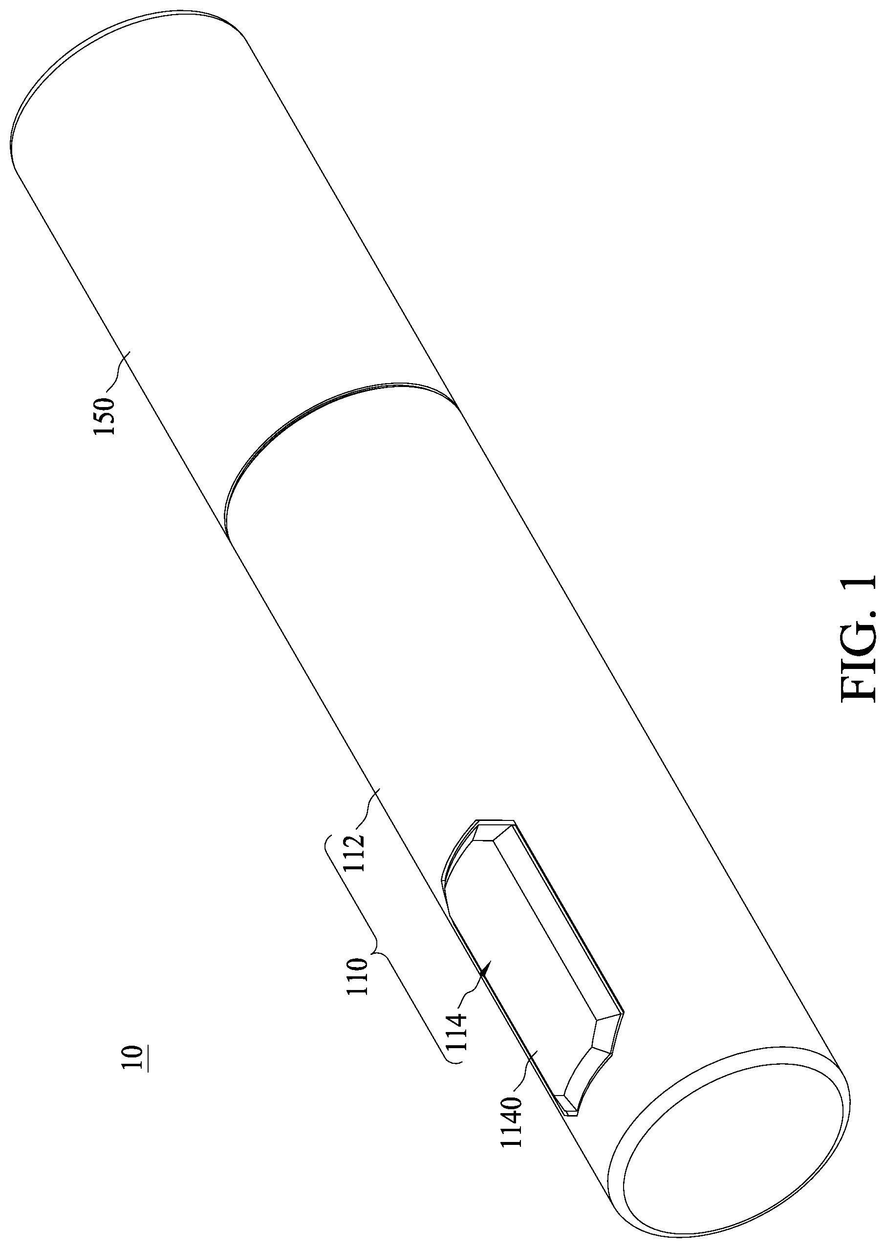
[0025] FIG. 1 is a perspective view of a package device in accordance with some embodiments of the present disclosure.
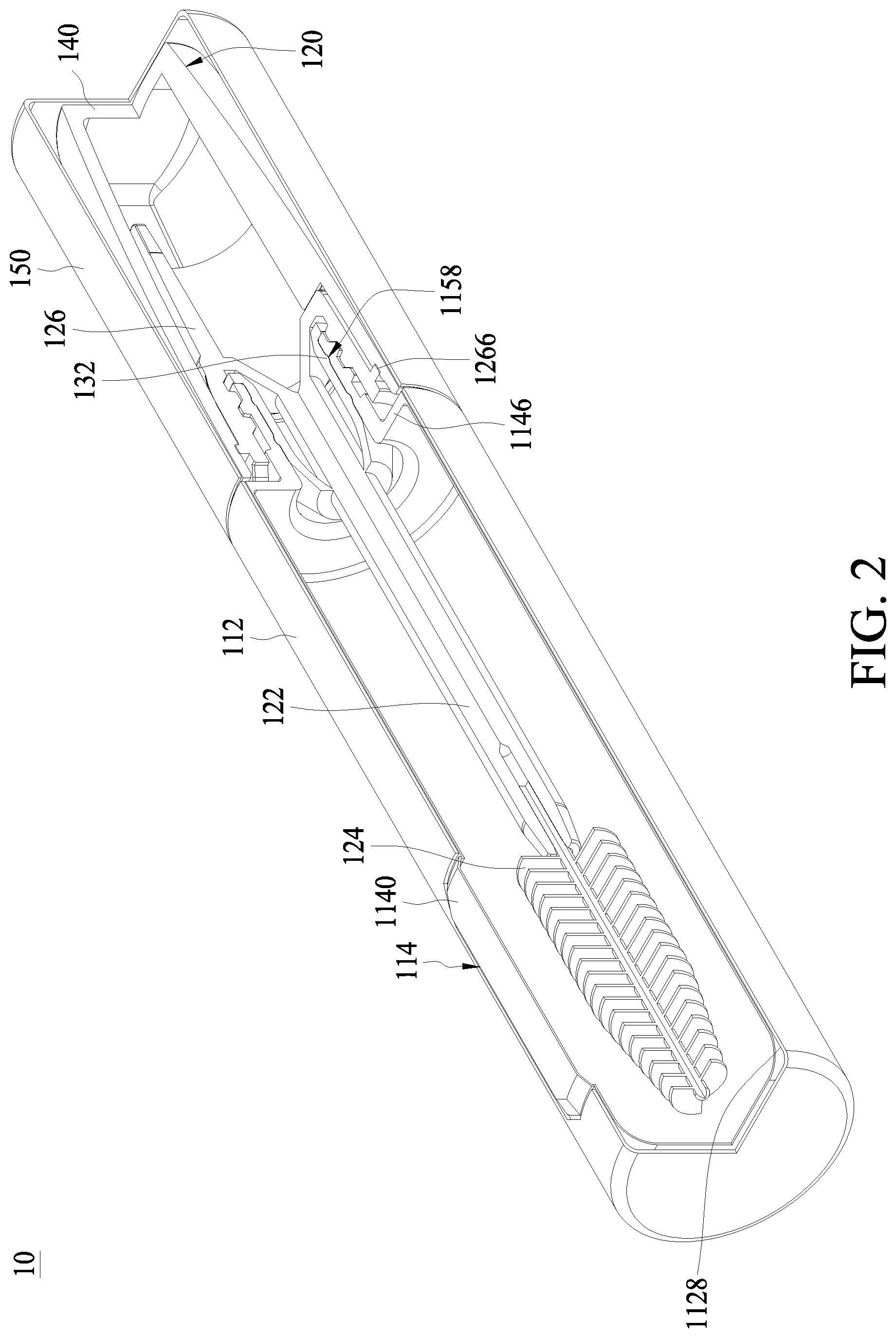
[0026] FIG. 2 is a perspective view of the package device of FIG. 1, with a portion of the package device shown as being cut longitudinally.
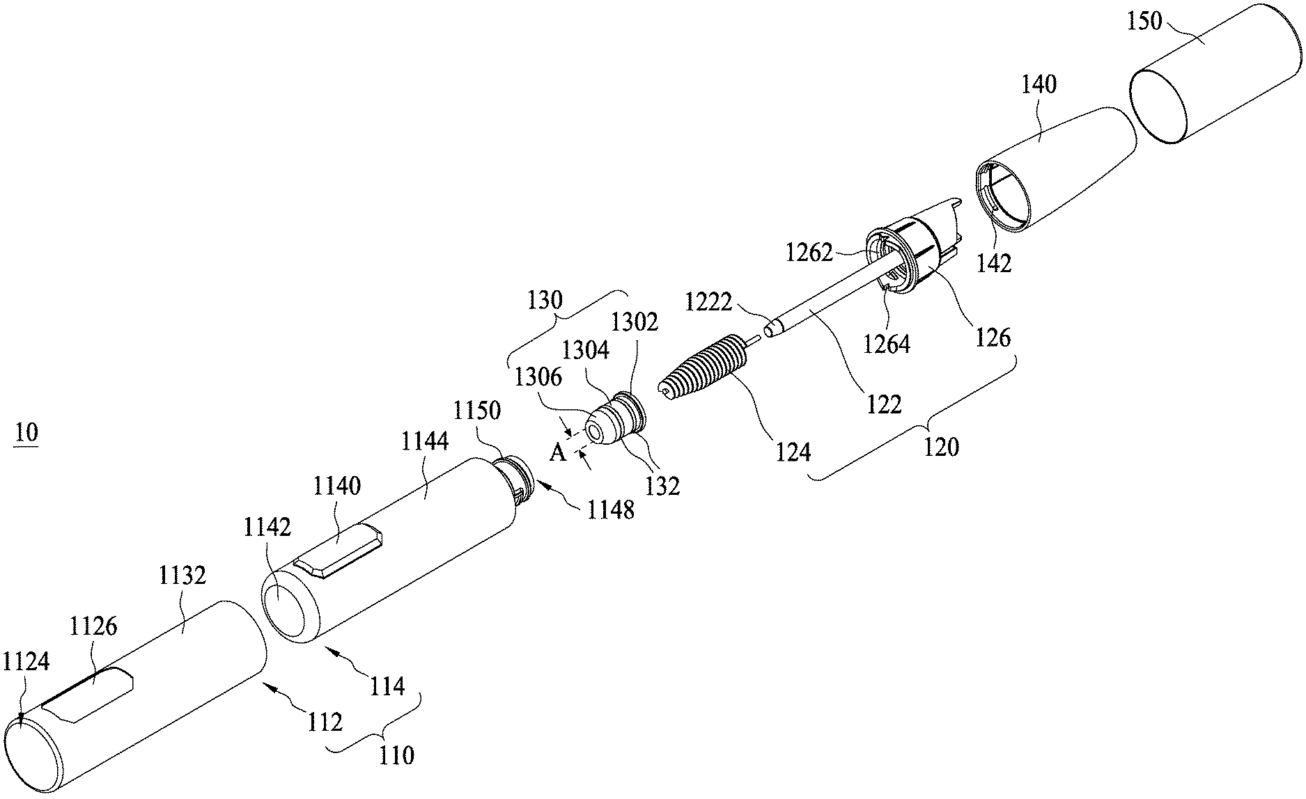
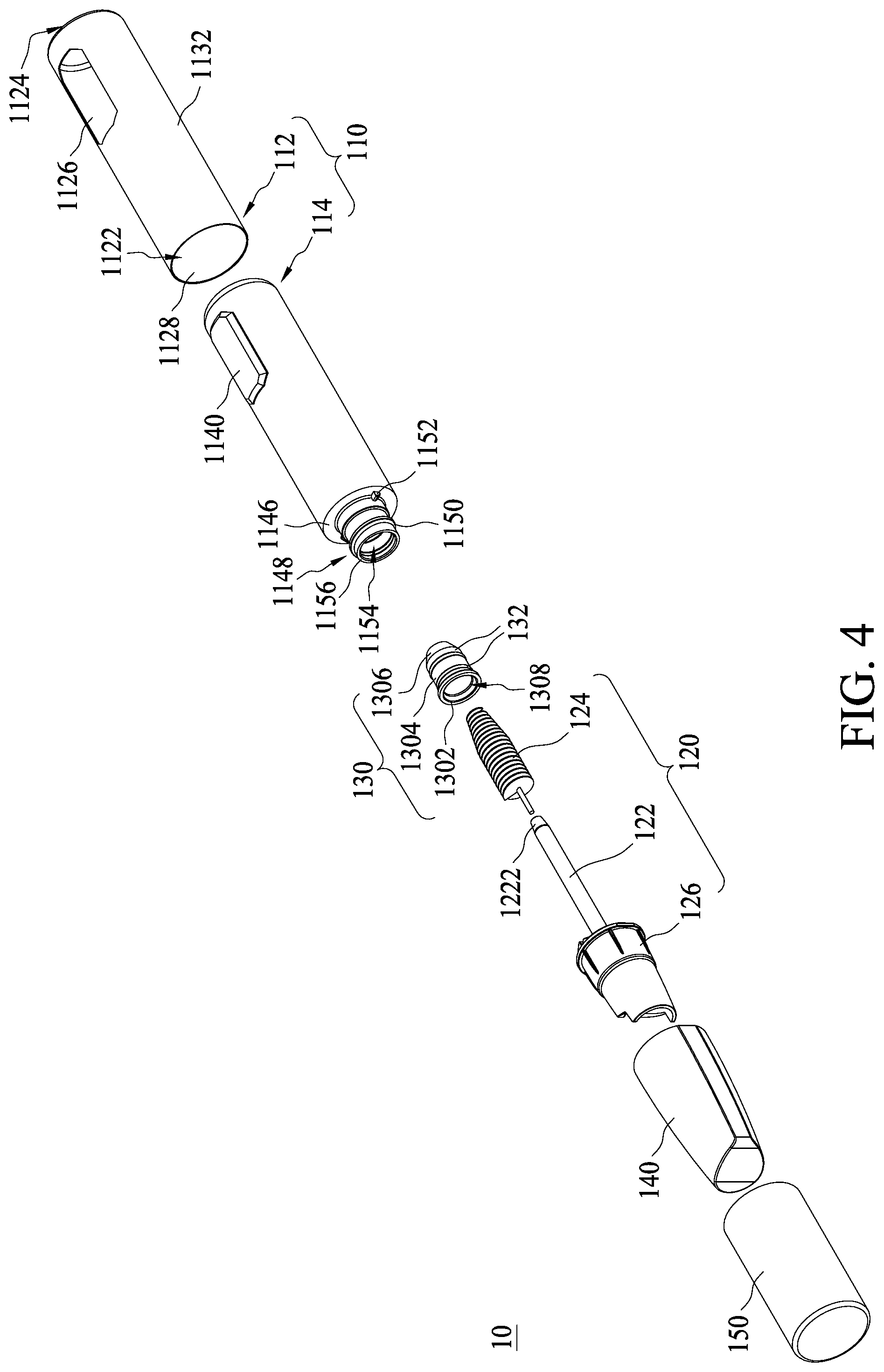
[0027] FIGS. 3 and 4 are exploded views of the package device of FIG. 1 at different view angles in accordance with some embodiments of the present disclosure.
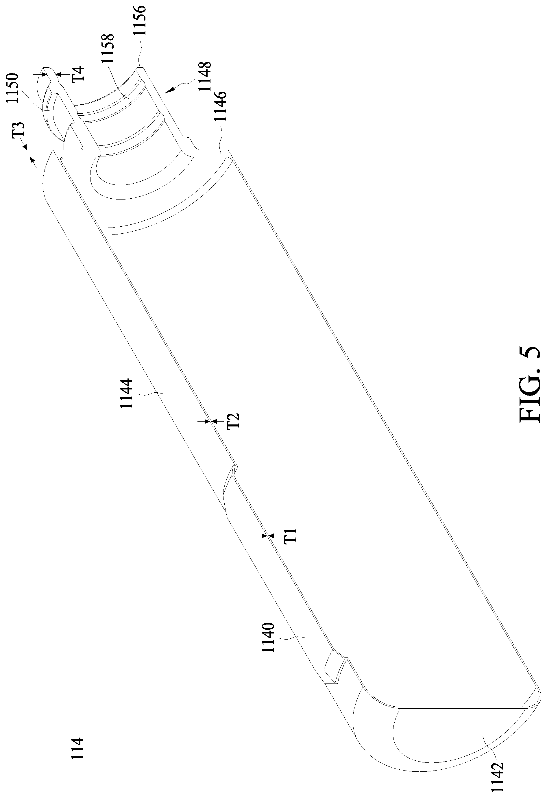
[0028] FIG. 5 is a sectional view of a bottle body of the package device of FIG. 1 in accordance with some embodiments of the present disclosure.
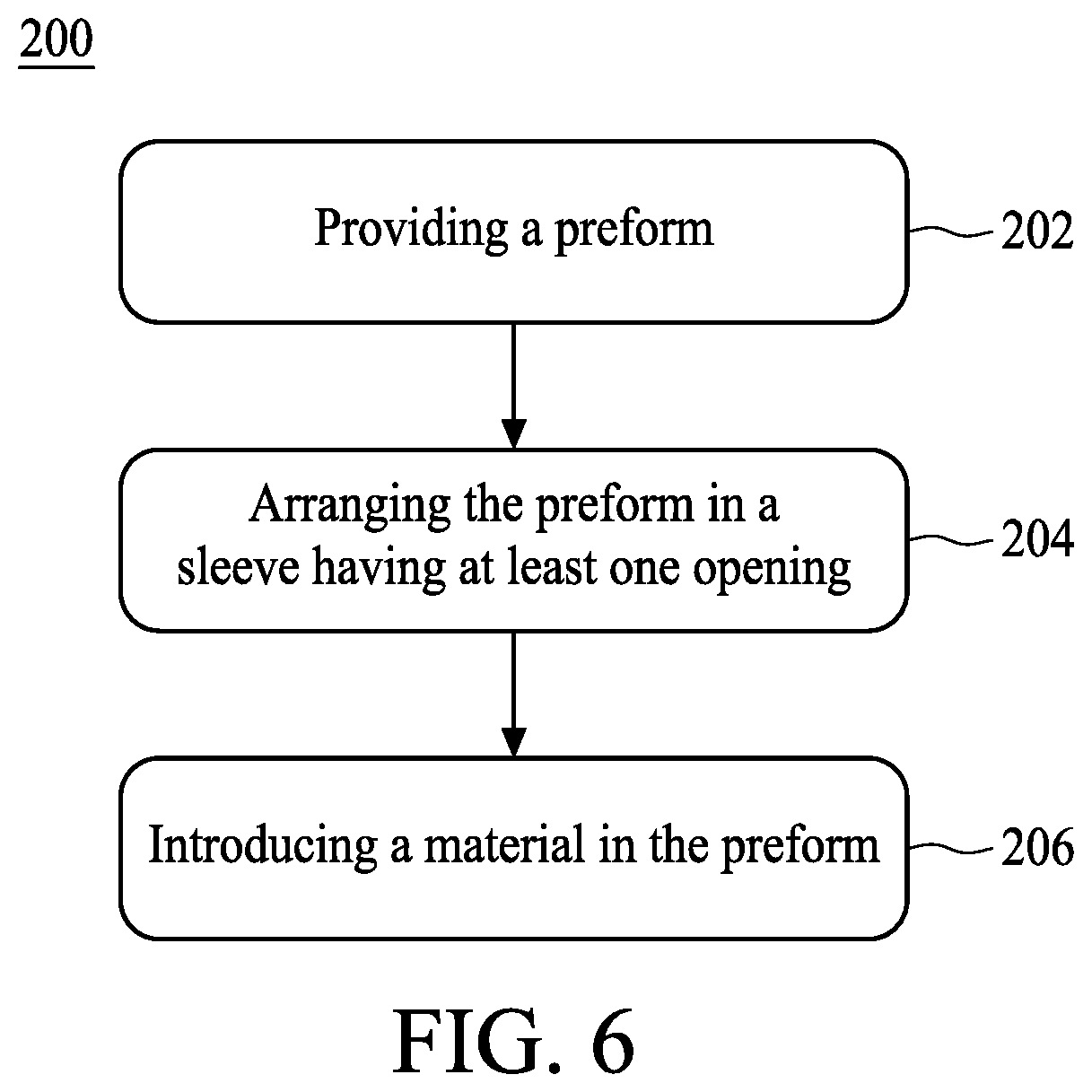
[0029] FIG. 6 is a flow diagram illustrating a method of manufacturing a package device in accordance with some embodiments of the present disclosure.
[0030] FIGS. 7 through 11 illustrate perspective views of intermediate stages in the formation of the package device in accordance with some embodiments of the present disclosure.
DETAILED DESCRIPTION
[0031] Embodiments, or examples, of the disclosure illustrated in the is drawings are now described using specific language. It shall be understood that no limitation of the scope of the disclosure is hereby intended. Any alteration or modification of the described embodiments, and any further applications of principles described in this document, are to be considered as normally occurring to one of ordinary skill in the art to which the disclosure relates. Reference numerals may be repeated throughout the embodiments, but this does not necessarily mean that feature(s) of one embodiment apply to another embodiment, even if they share the same reference numeral.
[0032] It shall be understood that, although the terms first, second, third, etc. may be used herein to describe various elements, components, regions, layers or sections, these elements, components, regions, layers or sections are not limited by these terms. Rather, these terms are merely used to distinguish one element, component, region, layer or section from another element, component, region, layer or section. Thus, a first element, component, region, layer or section discussed below could be termed a second element, component, region, layer or section without departing from the teachings of the present inventive concept.
[0033] The terminology used herein is for the purpose of describing particular example embodiments only and is not intended to be limited to the present inventive concept. As used herein, the singular forms "a," "an" and "the" are intended to include the plural forms as well, unless the context clearly indicates otherwise. It shall be further understood that the terms "comprises" and "comprising," when used in this specification, point out the presence of stated features, integers, steps, is operations, elements, or components, but do not preclude the presence or addition of one or more other features, integers, steps, operations, elements, components, or groups thereof.
[0034] FIG. 1 is a perspective view of a package device 10 in accordance with some embodiments of the present disclosure, FIG. 2 is a perspective view of the package device 10 of FIG. 1 with a portion of the package device 10 shown as being cut longitudinally, and FIGS. 3 and 4 are exploded views of the package device 10 of FIG. 1 at different view angles in accordance with some embodiments of the present disclosure. Referring to FIGS. 1 to 3, the package device 10 includes a packaging container 110 used for being filled with a cosmetic product (such as a mascara material) and an applicator 120 received in the packaging container 110.
[0035] In some embodiments, the packaging container 110 may be formed as an elongated cylindrical shape. In some embodiments, the shape of the packaging container 110 can be any shape, such as rectangular or the like. In some embodiments, the packaging container 110 includes a sleeve 112 and a bottle body 114 arranged in the sleeve 112.
[0036] Referring to FIGS. 3 and 4, in some embodiments, the sleeve 112 has an open front end 1122, a closed rear end 1124, and one or more through holes 1126 extending from an inner peripheral surface 1128 of the sleeve 112 to an outer peripheral surface 1132 of the sleeve 112. In some embodiments, the through holes 1126 may be shaped as closed geometric figures such as ovals, squares, rectangles, triangles, hexagons, hearts, stars, etc. In some embodiments, the sleeve 112 may be made of a first material such as a metal or a thermosetting plastic. In is some embodiments, the sleeve 112 may be made of anodized plastic to provide a metallic look.
[0037] FIG. 5 is a sectional view of the bottle body 114 in accordance with some embodiments of the present disclosure. Referring to FIG. 5, in some embodiments, the bottle body 114 includes a bottom wall 1142 and a peripheral wall 1144 connected to the bottom wall 1142. In some embodiments, one or more portions of the peripheral wall 1144 bend outwardly to form the curved portions 1140. In some embodiments, the curved portions 1140 have a thickness T1, which is substantially equal to a thickness T2 of other portions of the peripheral wall 1144. In some embodiments, the peripheral wall 1144 has a substantially uniform thickness.
[0038] Referring again to FIG. 2, in some embodiments, the bottle body 114 is fitted within the inner peripheral surface 1128 of the sleeve 112 and has one or more curved portions 1140 for being clasped within the through holes 1126 to securely retain the bottle body 114 within the sleeve 112. In some embodiments, the curved portions 1140 have one or more shapes that respectively correspond to the shapes of the through holes 1126.
[0039] Referring again to FIG. 5, in some embodiments, the bottle body 114 further includes a shoulder 1146 and a neck 1148, the shoulder 1146 is at an end of the bottle body 114 remote from the bottom wall 1142, the shoulder 1146 is connected to the peripheral wall 1144, and the neck 1148 is disposed contiguous with the shoulder 1146. In some embodiments, the shoulder 1146 has a thickness T3 substantially greater than the thickness T2 of the peripheral wall 1144, and the neck 1148 has a thickness T4 substantially greater than the is thickness T2. In some embodiments, the bottle body 114 may be transparent. In some embodiments, the bottle body 114 is made of a second material different from the first material of the sleeve 112. In some embodiments, the sleeve 112 and the bottle body 114 may have different colors, which may be considered aesthetically preferable in some situations. In some embodiments, the second material may be a thermoplastic elastomer (TPE), including but not limited to polyethylene terephthalate (PET) or polypropylene (PP), PET blends, polystyrene (PS), polycarbonate (PC), polybutylene terephthalate (PBT), PEN or combinations of such materials.
[0040] Referring again to FIGS. 2 to 4, in some embodiments, the applicator 120 includes a rod 122 formed as a solid body, a brush 124 installed at one end of the rod 122, and a grip 126 attached to the end of the rod 122 opposite to the brush 124. In some embodiments, the applicator 120 is withdrawn from the packaging container 110 by turning and removing the grip 126. In some embodiments, a diameter of the rod 122 at a distal end 1222 of the rod 122 close to the brush 124 gradually decreases at positions of decreasing distance from the brush 124. In some embodiments, the brush 124 is made of rubber. In some embodiments, the brush 124 may be used for applying the cosmetic product to an eyelash. In some embodiments, the rod 122 and the grip 126 may be integrally formed. In some embodiments, the rod 122 and the grip 126 are made of plastic material by molding. In some embodiments, the grip 126 is preferably sized to fit over a portion of the bottle body 114 and is capable of reversibly engaging the substantially cylindrical neck 1148 using any suitable reversible connector mechanism. In some embodiments, the grip 126 has internal threads 1262 which are threaded at external threads 1150 provided on is the neck 1148 for being secured on the bottle body 114. In some embodiments, the grip 126 further includes a depression 1264 for engaging a notch 1152 correspondingly provided on the neck 1148.
[0041] In some embodiments, the package device 10 further includes a wiper 130 installed in an opening 1154 of the bottle body 114 to sweep the cosmetic product. In some embodiments, the wiper 130 includes a flange 1302, a first annular segment 1304, and a second annular segment 1306; the first annular segment 1304 is sandwiched between the flange 1302 and the second annular segment 1306. In some embodiments, the flange 1302 is pressed against a rim 1156 of the neck 1148, and one or more protrusions 132 provided on the outer peripheral surface of the first annular segment 1034 are respectively engaged with one or more grooves 1158 formed on the inner peripheral surface of the neck 1148, thereby fixing the wiper 130 on the neck 1148.
[0042] In some embodiments, an aperture A of the second annular segment 1306 gradually decreases in size at positions of increasing distance from the first annular segment 1304. In some embodiments, the aperture A of the second annular segment 1306 at the position distal from the first annular segment 1304 is substantially equal to or slightly greater than a diameter of the rod 122, such that when the brush 124 of the applicator 120 passes through the opening 1308 in the wiper 130 at the time of removing the brush 124 from the packaging container 110, a portion of the cosmetic product adhering to the brush 124 can be squeezed off effectively, and as a result, it is possible to prevent the cosmetic product from adhering excessively to the brush 124 and dripping, and to prevent the cosmetic product from spilling out of the packaging container 110 at the time of application.
[0043] In some embodiments, the package device 10 further includes an inner cap 140 and an outer cap 150. The grip 126 is preferably sized to fit over a portion of the inner cap 140 and is engaged with the inner cap 140 using any suitable reversible connector mechanism. In some embodiments, the inner cap 140 includes one or more blocks 142 for engaging with one or more slots 1266 provided on the grip 126. In some embodiments, the outer cap 150 receives the inner cap 140. In some embodiments, a material of the outer cap 150 may be the same as that of the sleeve 112.
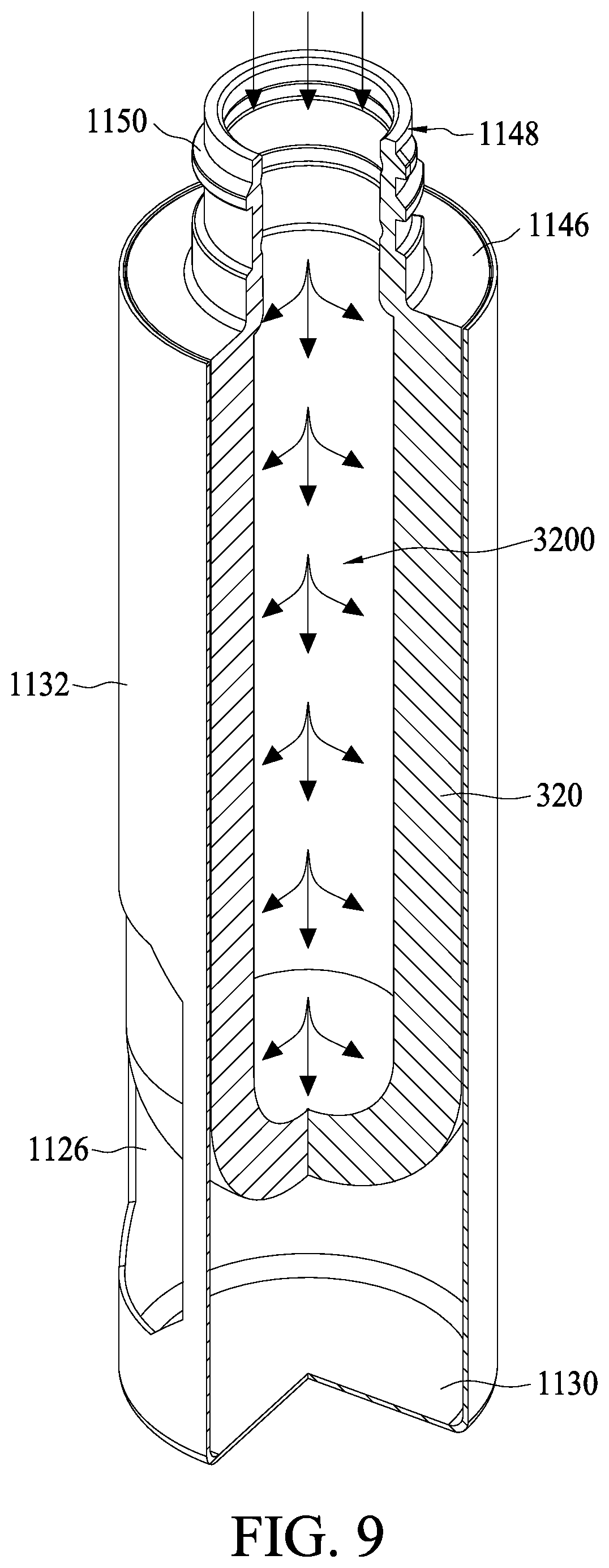
[0044] FIG. 6 is a flow diagram illustrating a method 200 of manufacturing the packaging container 110 of FIG. 1 in accordance with some embodiments of the present disclosure. FIGS. 7 to 10 are schematic diagrams illustrating various fabrication stages constructed according to the method 200 of manufacturing the packaging container 110 in accordance with some embodiments of the present disclosure. The stages shown in FIGS. 7 to 10 are also illustrated schematically in the flow diagram in FIG. 6. In the subsequent discussion, the fabrication stages shown in FIGS. 7 to 10 are discussed in reference to the process steps in FIG. 6.
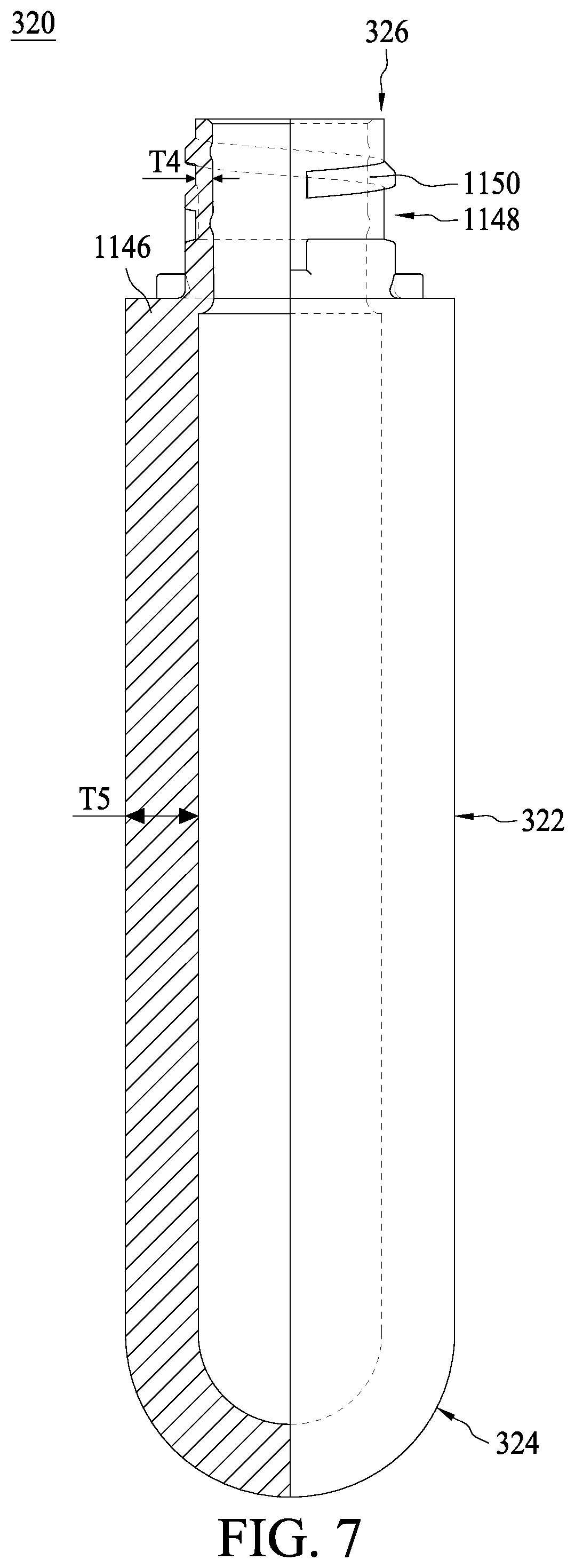
[0045] Referring to FIG. 7, a preform 320 is provided according to a step 202 in FIG. 6. In some embodiments, the preform 320 is a precursor of the bottle body 114 shown in FIG. 5. In some embodiments, the preform 320 may have a tube shape made by injection molding or extrusion thermoplastic elastomers, such as PET or PP. However, the preform 320 may also be made of a different material, such as but not limited to PET blends, polystyrene (PS), polycarbonate (PC), polybutylene terephthalate (PBT), PEN or a is combination of such materials. In some embodiments, the preform 320 has a cylindrical body 322 having a closed end 324 and an open end 326. In some embodiments, the preform 320 further includes a shoulder 1146 connected to the open end 326 and a neck 1148 disposed contiguous with the shoulder 1146. In some embodiments, an outer surface of the neck 1148 is provided with external threads 1150. In some embodiments, a thickness T5 of the cylindrical body 322 is greater than a thickness T4 of the neck 1148. In some embodiments, one or more patterns may be previously formed on the cylindrical body 322. In some embodiments, the preform 320 may be manufactured using injection molding.
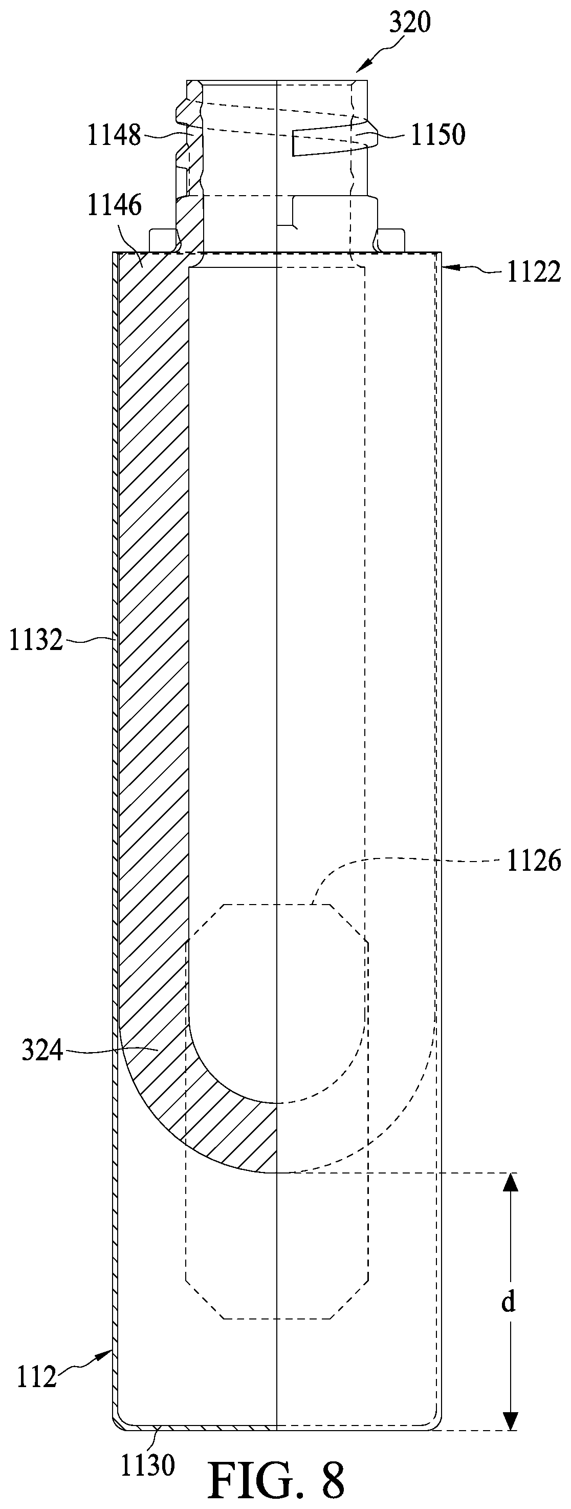
[0046] Referring to FIG. 8, in some embodiments, the preform 320 is arranged in a sleeve 112 according a step 204 in FIG. 6. In some embodiments, the shoulder 1146 is engaged at the open front end 1122 of the sleeve 112, and the closed end 324 of the preform 320 is separated from a bottom wall 1130 of the sleeve 112 by a distance d. In some embodiments, the sleeve 112 further includes a peripheral wall 1132 connected to the bottom wall 1130. In some embodiments, the sleeve 112 has one or more through holes 1126, penetrating through the peripheral wall 1132. In some embodiments, the one or more patterns formed on the cylindrical body 322 with profiles corresponding to the through holes 1126. In some embodiments, the sleeve 112 may be made of metal or thermosetting plastic, and may be manufactured by molding. In some embodiments, the preform 320 may be heated to a temperature that is below the melting temperature of the preform, but sufficiently high to be pliable after being arranged into the sleeve 112, such that the preform 320 can be stretched in a longitudinal direction.
[0047] Referring to FIGS. 9 and 10, in some embodiments, a material, such as compressed air or centrifugal force, is introduced into an inner space 3200 of the preform 320 according to a step 208 in FIG. 6. Accordingly, the preform 320 is stretched to the bottom wall 1130 of the sleeve 112 to form the bottle body 114, wherein a portion of bottle body 114 is bent outwardly to form the curved portion clasped within the through hole, and thus the packaging container 110 as shown in FIG. 10 is formed.
[0048] FIG. 11 illustrates the formation of bottle body 114 in accordance with alternative embodiments. Referring to FIG. 11, the preform 320' being a precursor of the bottle body 114 shown in FIG. 5 is arranged in a sleeve 112. In some embodiments, the preform 320' may be made of thermoplastic elastomers, such as PET, PP, PET blends, PS, PC, PBT, PEN or a combination of such materials. In some embodiments, the preform 320' has a collapsible liner body 322', a shoulder 1146 connected to the collapsible liner body 322', and a neck 1148 disposed contiguous with the shoulder 1146. In some embodiments, an outer surface of the neck 1148 is provided with external threads 1150. In some embodiments, and a thickness T of the collapsible liner 322' is less the thickness T4 of the neck 1148.
[0049] In some embodiments, the shoulder 1146 is engaged at the open front end 1122 of the sleeve 112. In some embodiments, the sleeve 112 further includes a peripheral wall 1132 connected to the bottom wall 1130. In some embodiments, the sleeve 112 has one or more through holes 1126, penetrating through the peripheral wall 1132. In some embodiments, the preform 320' may be heated to a temperature that is below the melting temperature of the preform 320', but sufficiently high to be pliable after being arranged into the sleeve 112, such that the preform 320' can be stretched in a longitudinal direction.
[0050] Next, a material, such as compressed air or centrifugal force, is introduced into an inner space 3200' of the preform 320' according to a step 208 in FIG. 6. Accordingly, the preform 320' is stretched to the bottom wall 1130 of the sleeve 112 to form the bottle body 114, wherein a portion of bottle body 114 is bent outwardly to form the curved portion clasped within the through hole, and thus the packaging container 110 as shown in FIG. 10 is formed.
[0051] One aspect of the present disclosure provides a packaging container. The packaging container includes a sleeve and a bottle body. The sleeve has at least one through hole. The bottle body is fitted within an inner peripheral surface of the sleeve and has at least one curved portion for being clasped within the through hole.
[0052] One aspect of the present disclosure provides a package device. The package device includes a packaging container and an applicator. The packaging container includes a sleeve having at least one through hole and a bottle body fitted within an inner peripheral surface of the sleeve and having at least one curved portion being clasped within the through hole. The applicator includes a rod, a brush, and a grip. The brush is installed at one end of the rod, and the rod and the brush are stored in the packaging container. The grip is attached to the end of the rod opposite to the brush, and the grip is coupled to an open end of the bottle body. The rod and the brush are withdrawn from the packaging container by turning and removing the grip.
[0053] One aspect of the present disclosure provides a method of manufacturing a package device. The method includes steps of providing a preform comprising a body, a shoulder connected to an open end of the body, and a neck disposed contiguous with the shoulder; arranging the preform in a sleeve having at least one through hole, wherein the shoulder is engaged at an open front end of the sleeve; and introducing a material into an inner space of the preform to stretch the preform and form at least one curved portion clasped within the through hole.
[0054] Although the present disclosure and its advantages have been described in detail, it should be understood that various changes, substitutions and alterations can be made herein without departing from the spirit and scope of the disclosure as defined by the appended claims. For example, many of the processes discussed above can be implemented in different methodologies and replaced by other processes, or a combination thereof.
[0055] Moreover, the scope of the present application is not intended to be limited to the particular embodiments of the process, machine, manufacture, and composition of matter, means, methods and steps described in the specification. As one of ordinary skill in the art will readily appreciate from the present disclosure, processes, machines, manufacture, compositions of matter, means, methods, or steps, presently existing or later to be developed, that perform substantially the same function or achieve substantially the same result as the corresponding embodiments described herein may be utilized according to the present disclosure. Accordingly, the appended claims are intended to include within their scope such processes, machines, manufacture, compositions of matter, means, methods, and steps.
* * * * *
D00000
D00001
D00002
D00003
D00004
D00005
D00006
D00007
D00008
D00009
D00010
D00011
XML
uspto.report is an independent third-party trademark research tool that is not affiliated, endorsed, or sponsored by the United States Patent and Trademark Office (USPTO) or any other governmental organization. The information provided by uspto.report is based on publicly available data at the time of writing and is intended for informational purposes only.
While we strive to provide accurate and up-to-date information, we do not guarantee the accuracy, completeness, reliability, or suitability of the information displayed on this site. The use of this site is at your own risk. Any reliance you place on such information is therefore strictly at your own risk.
All official trademark data, including owner information, should be verified by visiting the official USPTO website at www.uspto.gov. This site is not intended to replace professional legal advice and should not be used as a substitute for consulting with a legal professional who is knowledgeable about trademark law.