Tough Iron-Based Glasses with High Glass Forming Ability and High Thermal Stability
Na; Jong Hyun ; et al.
U.S. patent application number 16/719838 was filed with the patent office on 2020-08-20 for tough iron-based glasses with high glass forming ability and high thermal stability. This patent application is currently assigned to GlassiMetal Technology, Inc.. The applicant listed for this patent is GlassiMetal Technology, Inc.. Invention is credited to Marios D. Demetriou, Kyung-Hee Han, William L. Johnson, Jong Hyun Na.
| Application Number | 20200263267 16/719838 |
| Document ID | 20200263267 / US20200263267 |
| Family ID | 1000004605963 |
| Filed Date | 2020-08-20 |
| Patent Application | download [pdf] |


View All Diagrams
| United States Patent Application | 20200263267 |
| Kind Code | A1 |
| Na; Jong Hyun ; et al. | August 20, 2020 |
Tough Iron-Based Glasses with High Glass Forming Ability and High Thermal Stability
Abstract
The disclosure provides Fe--Cr--Ni--Mo--P--C--B metallic glass-forming alloys and metallic glasses that have a high glass forming ability along with a high thermal stability of the supercooled liquid against crystallization.
| Inventors: | Na; Jong Hyun; (Pasadena, CA) ; Han; Kyung-Hee; (Pasadena, CA) ; Demetriou; Marios D.; (West Hollywood, CA) ; Johnson; William L.; (San Marino, CA) | ||||||||||
| Applicant: |
|
||||||||||
|---|---|---|---|---|---|---|---|---|---|---|---|
| Assignee: | GlassiMetal Technology,
Inc. Pasadena CA |
||||||||||
| Family ID: | 1000004605963 | ||||||||||
| Appl. No.: | 16/719838 | ||||||||||
| Filed: | December 18, 2019 |
Related U.S. Patent Documents
| Application Number | Filing Date | Patent Number | ||
|---|---|---|---|---|
| 62805845 | Feb 14, 2019 | |||
| Current U.S. Class: | 1/1 |
| Current CPC Class: | C21D 6/001 20130101; C22C 38/08 20130101; C22C 38/12 20130101; C22C 38/002 20130101; C22C 33/04 20130101 |
| International Class: | C21D 6/00 20060101 C21D006/00; C22C 38/12 20060101 C22C038/12; C22C 38/08 20060101 C22C038/08; C22C 38/00 20060101 C22C038/00; C22C 33/04 20060101 C22C033/04 |
Claims
1. A metallic glass-forming alloy having a composition represented by the following formula: Fe.sub.(100-a-b-c-d-e-f)Cr.sub.aNi.sub.bMo.sub.cP.sub.dC.sub.eB.sub.f where: a is up to 10 atomic percent, b ranges from 3 to 13 atomic percent, c ranges from 2 to 7 atomic percent, d+e+f ranges from 21.25 to 23.75 atomic percent, e ranges from 4.5 to 8; atomic percent, and f ranges from 1 to 9 atomic percent; and wherein the metallic glass-forming alloy has a critical rod diameter of at least 3 mm, and wherein the thermal stability of the supercooled liquid of a metallic glass formed from the metallic glass-forming alloy against crystallization is at least 45.degree. C.
2. The metallic glass-forming alloy of claim 1, wherein a is up to 9 atomic percent, b ranges from 4 to 12 atomic percent, c ranges from 3 to 6.5 atomic percent, d+e+f ranges from 21.5 to 23.5 atomic percent, e ranges from 5.25 to 7.5 atomic percent, and f ranges from 1.5 to 8.5 atomic percent, wherein the metallic glass-forming alloy has a critical rod diameter of at least 4 mm, and wherein the thermal stability of the supercooled liquid of the metallic glass forming alloy formed from the metallic glass-forming alloy against crystallization is at least 47.5.degree. C.
3. The metallic glass-forming alloy of claim 1, wherein a is less than 3.5 atomic percent, and wherein the critical bending diameter of the metallic glass formed from the metallic glass-forming alloy is at least 0.5 mm.
4. The metallic glass-forming alloy of claim 1, wherein c ranges from 2 to less than 6.5 atomic percent, and wherein the critical bending diameter of the metallic glass formed from the metallic glass-forming alloy is at least 0.6 mm.
5. The metallic glass-forming alloy of claim 1, wherein d+e+f ranges from 21.25 to less than 23.5 atomic percent, and wherein the critical bending diameter of the metallic glass formed from the metallic glass-forming alloy is at least 0.6 mm.
6. The metallic glass-forming alloy of claim 1, wherein e ranges from greater than 5.25 to 8 atomic percent, and wherein the critical bending diameter of the metallic glass formed from the metallic glass-forming alloy is at least 0.8 mm.
7. The metallic glass-forming alloy of claim 1, wherein f ranges from 1 to less than 5 atomic percent, and wherein the critical bending diameter of the metallic glass formed from the metallic glass-forming alloy is at least 0.5 mm.
8. The metallic glass-forming alloy of claim 1, wherein up to 5 atomic percent of Fe is substituted by Co, Ru, Mn, or a combination thereof.
9. The metallic glass-forming alloy of claim 1, wherein up to 2 atomic percent of Ni is substituted by Pd, Pt, or a combination thereof.
10. The metallic glass-forming alloy of claim 1, wherein up to 1 atomic percent of Mo is substituted by Nb, Ta, V, W, or a combination thereof.
11. The metallic glass-forming alloy of claim 1, wherein up to 2 atomic percent of P is substituted by Si.
12. A method for forming a metallic glass comprising: providing a sample of a metallic glass-forming alloy having a composition represented by the following formula: Fe.sub.(100-a-b-c-d-e-f)Cr.sub.aNi.sub.bMo.sub.cP.sub.dC.sub.eB.sub.f where: a is up to 10 atomic percent, b ranges from 3 to 13 atomic percent, c ranges from 2 to 7 atomic percent, d+e+f ranges from 21.25 to 23.75 atomic percent, e ranges from 4.5 to 8; atomic percent, and f ranges from 1 to 9 atomic percent, and wherein the metallic glass-forming alloy has a critical rod diameter of at least 3 mm, and wherein the thermal stability of the supercooled liquid of a metallic glass formed from the metallic glass-forming alloy against crystallization is at least 45.degree. C.; heating and melting the sample of the metallic glass-forming alloy under inert atmosphere to create a molten alloy; and quenching the molten alloy fast enough to avoid crystallization of the molten alloy.
13. The method of claim 12, further comprising, prior to quenching, heating the molten alloy to at least 100.degree. C. above the liquidus temperature of the metallic glass-forming alloy.
14. The method of claim 12, further comprising, prior to quenching, heating the molten alloy to at least 1200.degree. C.
15. A method of thermoplastically shaping a metallic glass into an article, comprising: providing a sample of a metallic glass having a composition represented by the following formula: Fe.sub.(100-a-b-c-d-e-f)Cr.sub.aNi.sub.bMo.sub.cP.sub.dC.sub.eB.sub.f where: a is up to 10 atomic percent, b ranges from 3 to 13 atomic percent, c ranges from 2 to 7 atomic percent, d+e+f ranges from 21.25 to 23.75 atomic percent, e ranges from 4.5 to 8; atomic percent, and f ranges from 1 to 9 atomic percent, and wherein the thermal stability of the supercooled liquid of the metallic glass against crystallization is at least 45.degree. C.; heating the sample to a softening temperature T.sub.o above the glass transition temperature T.sub.g, of the metallic glass to create a heated sample; applying a deformational force to shape the heated sample over a time t.sub.o that is shorter than the time it takes for the metallic glass to crystallize at T.sub.o; and cooling the heated sample to a temperature below T.sub.g to form an article.
16. The method of claim 15, wherein T.sub.o is higher than T.sub.g and lower than the liquidus temperature of a metallic glass-forming alloy having the composition of the metallic glass.
17. The method of claim 15, wherein T.sub.o is in the range of 550 to 850.degree. C.
18. The method of claim 15, wherein T.sub.o is such that the supercooling temperature is in the range of 200 to 300.degree. C.
19. The method of claim 15, wherein T.sub.o is such that the normalized supercooling temperature is in the range of 0.25 to 0.5.
20. The method of claim 15, wherein the viscosity of the sample at T.sub.o is less than 10.sup.5 Pa-s.
Description
CROSS-REFERENCE TO RELATED APPLICATIONS
[0001] The present application claims priority under 35 U.S.C. 119(e) to U.S. Provisional Application No. 62/805,845, entitled "Tough Iron-Based Glasses with High Glass Forming Ability and High Thermal Stability" to Na et al., filed Feb. 14, 2019, the disclosure of which is incorporated herein by reference in its entirety.
FIELD
[0002] The disclosure is directed to Fe--Cr--Mo--Ni--P--C--B metallic glasses having a high glass forming ability and a high thermal stability of the supercooled liquid against crystallization.
BACKGROUND
[0003] U.S. Pat. Nos. 8,529,712 and 8,911,572 entitled "Tough Iron-Based Bulk Metallic Glass Alloys," the disclosures of which is incorporated herein by reference in their entirety, disclose Fe-based glass forming alloys comprising at least P, C, and B demonstrating a critical rod diameter of at least 2 mm and a shear modulus of less than 60 GPa, where the Fe atomic concentration is at least 60 percent, the P atomic concentration varies in the range of 5 to 17.5 percent, the C atomic concentration varies in the range of 3 to 6.5 percent, and the B atomic concentration varies in the range of 1 to 3.5 percent. The patents also disclose that the Fe-based alloys may optionally comprise Mo in an atomic concentration varying in the range of 2 to 8 percent, Cr in an atomic concentration varying in the range of 1 to 7 percent, and Ni in an atomic concentration varying in the range of 3 to 7 percent. The patents present several examples of amorphous Fe--P--C--B alloys that comprise Mo, Cr, and Ni demonstrating a critical rod diameter of up to 6 mm and a thermal stability of the supercooled liquid (i.e. a difference between the crystallization and glass transition temperatures at a heating rate of 20 K/min) of under 40.degree. C.
BRIEF DESCRIPTION OF THE DRAWINGS
[0004] The description will be more fully understood with reference to the following figures and data graphs, which are presented as various embodiments of the disclosure and should not be construed as a complete recitation of the scope of the disclosure, wherein:
[0005] FIG. 1 provides calorimetry scans for sample metallic glasses according to Fe.sub.67Ni.sub.7Mo.sub.4P.sub.19.5-xC.sub.xB.sub.2.5 in accordance with embodiments of the disclosure. The glass transition temperature T.sub.g and crystallization temperature T.sub.x are indicated by arrows.
[0006] FIG. 2 provides a data plot showing the effect of substituting P by C according to the composition formula Fe.sub.67Ni.sub.7Mo.sub.4P.sub.19.5-xC.sub.xB.sub.2.5 on the glass-transition and crystallization temperatures and thermal stability of the supercooled liquid .DELTA.T.sub.x in accordance with embodiments of the disclosure.
[0007] FIG. 3 provides a data plot showing the effect of substituting P by C according to the composition formula Fe.sub.67Ni.sub.7Mo.sub.4P.sub.19.5-xC.sub.xB.sub.2.5 on the critical rod diameter of the alloys in accordance with embodiments of the disclosure.
[0008] FIG. 4 provides calorimetry scans for sample metallic glasses according to Fe.sub.67Ni.sub.7Mo.sub.4P.sub.16-xC.sub.6B.sub.x in accordance with embodiments of the disclosure. The glass transition temperature T.sub.g and crystallization temperature T.sub.x are indicated by arrows.
[0009] FIG. 5 provides a data plot showing the effect of substituting P by B according to the composition formula Fe.sub.67Ni.sub.7Mo.sub.4P.sub.16-xC.sub.6B.sub.x on the glass-transition and crystallization temperatures and thermal stability of the supercooled liquid .DELTA.T.sub.x in accordance with embodiments of the disclosure.
[0010] FIG. 6 provides a data plot showing the effect of substituting P by B according to the composition formula Fe.sub.67Ni.sub.7Mo.sub.4P.sub.16-xC.sub.6B.sub.x on the critical rod diameter of the alloys in accordance with embodiments of the disclosure.
[0011] FIG. 7 provides calorimetry scans for sample metallic glasses according to Fe.sub.71-xNi.sub.7Mo.sub.xP.sub.13.5C.sub.6B.sub.2.5 in accordance with embodiments of the disclosure. The glass transition temperature T.sub.g and crystallization temperature T.sub.x are indicated by arrows.
[0012] FIG. 8 provides a data plot showing the effect of substituting Fe by Mo according to the composition formula Fe.sub.71-xNi.sub.7Mo.sub.xP.sub.13.5C.sub.6B.sub.2.5 on the glass-transition and crystallization temperatures and thermal stability of the supercooled liquid .DELTA.T.sub.x in accordance with embodiments of the disclosure.
[0013] FIG. 9 provides a data plot showing the effect of substituting Fe by Mo according to the composition formula Fe.sub.71-xNi.sub.7Mo.sub.xP.sub.13.5C.sub.6B.sub.2.5 on the critical rod diameter of the alloys in accordance with embodiments of the disclosure.
[0014] FIG. 10 provides calorimetry scans for sample metallic glasses according to Fe.sub.74-xNi.sub.xMo.sub.4P.sub.13.5C.sub.6B.sub.2.5 in accordance with embodiments of the disclosure. The glass transition temperature T.sub.g and crystallization temperature T.sub.x are indicated by arrows.
[0015] FIG. 11 provides a data plot showing the effect of substituting Fe by Ni according to the composition formula Fe.sub.74-xNi.sub.xMo.sub.4P.sub.13.5C.sub.6B.sub.2.5 on the glass-transition and crystallization temperatures and thermal stability of the supercooled liquid .DELTA.T.sub.x in accordance with embodiments of the disclosure.
[0016] FIG. 12 provides a data plot showing the effect of substituting Fe by Ni according to the composition formula Fe.sub.74-xNi.sub.xMo.sub.4P.sub.13.5C.sub.6B.sub.2.5 on the critical rod diameter of the alloys in accordance with embodiments of the disclosure.
[0017] FIG. 13 provides calorimetry scans for sample metallic glasses according to Fe.sub.65-xNi.sub.9Cr.sub.xMo.sub.4P.sub.13.5C.sub.6B.sub.2.5 in accordance with embodiments of the disclosure. The glass transition temperature T.sub.g and crystallization temperature T.sub.x are indicated by arrows.
[0018] FIG. 14 provides a data plot showing the effect of introducing Cr at the expense of Fe according to the composition formula Fe.sub.65-xNi.sub.9Cr.sub.xMo.sub.4P.sub.13.5C.sub.6B.sub.2.5 on the glass-transition and crystallization temperatures and thermal stability of the supercooled liquid .DELTA.T.sub.x in accordance with embodiments of the disclosure.
[0019] FIG. 15 provides a data plot showing the effect of introducing Cr at the expense of Fe according to the composition formula Fe.sub.65-xNi.sub.9Cr.sub.xMo.sub.4P.sub.13.5C.sub.6B.sub.2.5 on the critical rod diameter of the alloys in accordance with embodiments of the disclosure.
[0020] FIG. 16 provides calorimetry scans for sample metallic glasses according to [Fe.sub.0.814Ni.sub.0.116Cr.sub.0.019Mo.sub.0.051].sub.100-x[P.sub.0.613C- .sub.0.273B.sub.0.114].sub.x in accordance with embodiments of the disclosure. The glass transition temperature T.sub.g and crystallization temperature T.sub.x are indicated by arrows.
[0021] FIG. 17 provides a data plot showing the effect of substituting metals by metalloids according to the composition formula [Fe.sub.0.814Ni.sub.0.116Cr.sub.0.019Mo.sub.0.051].sub.100-x[P.sub.0.613C- .sub.0.273B.sub.0.114].sub.x on the glass-transition and crystallization temperatures and thermal stability of the supercooled liquid .DELTA.T.sub.x in accordance with embodiments of the disclosure.
[0022] FIG. 18 provides a data plot showing the effect of substituting metals by metalloids according to the composition formula [Fe.sub.0.814Ni.sub.0.116Cr.sub.0.019Mo.sub.0.051].sub.100-x[P.sub.0.613C- .sub.0.273B.sub.0.114].sub.x on the critical rod diameter of the alloys in accordance with embodiments of the disclosure.
[0023] FIG. 19 illustrates a 7 mm rod of metallic glass Fe.sub.63.5Ni.sub.9Cr.sub.1.5Mo.sub.4P.sub.13.5C.sub.6B.sub.2.5 (Example 33) processed by water quenching the high temperature melt in a fused silica tube having a wall thickness of 0.5 mm.
[0024] FIG. 20 illustrates an x-ray diffractogram verifying the amorphous structure a 7 mm rod of metallic glass Fe.sub.63.5Ni.sub.9Cr.sub.1.5Mo.sub.4P.sub.13.5C.sub.6B.sub.2.5 (Example 33).
[0025] FIG. 21 illustrates a plastically-bent 0.4 mm diameter rod of metallic glass Fe.sub.63.5Ni.sub.9Cr.sub.1.5Mo.sub.4P.sub.13.5C.sub.6B.sub.2.5 (Example 33), a plastically-bent 0.6 mm diameter rod of metallic glass Fe.sub.63.5Ni.sub.9Cr.sub.1.5Mo.sub.4P.sub.13.5C.sub.6B.sub.2.5 (Example 33), and a fractured 0.8 mm diameter rod of metallic glass Fe.sub.63.5Ni.sub.9Cr.sub.1.5Mo.sub.4P.sub.13.5C.sub.6B.sub.2.5 (Example 33).
BRIEF SUMMARY
[0026] The disclosure provides Fe--Cr--Ni--Mo--P--C--B metallic glass-forming alloys and metallic glasses that have a high glass forming ability along with a high thermal stability of the supercooled liquid against crystallization.
[0027] In one embodiment, the disclosure provides a metallic glass-forming alloy or a metallic glass having a composition represented by the following formula (subscripts denote atomic percentages):
Fe.sub.(100-a-b-c-d-e-f)Cr.sub.aNi.sub.bMo.sub.cP.sub.dC.sub.eB.sub.f EQ. (1) [0028] where: [0029] a is up to 10; [0030] b ranges from 3 to 13; [0031] c ranges from 2 to 7; [0032] d+e+f ranges from 21.25 to 23.75; [0033] e ranges from 4.5 to 8; and [0034] f ranges from 1 to 9. [0035] wherein the metallic glass-forming alloy has a critical rod diameter of at least 3 mm, and [0036] wherein the thermal stability of the supercooled liquid of the metallic glass against crystallization is at least 45.degree. C.
[0037] In another embodiment of the metallic glass-forming alloy or metallic glass, a is up to 9, b ranges from 4 to 12, c ranges from 3 to 6.5, d+e+f ranges from 21.5 to 23.5, e ranges from 5.25 to 7.5, f ranges from 1.5 to 8.5, wherein the metallic glass-forming alloy has a critical rod diameter of at least 4 mm, and wherein the thermal stability of the supercooled liquid of the metallic glass against crystallization is at least 47.5.degree. C.
[0038] In another embodiment of the metallic glass-forming alloy or metallic glass, a is up to 8, b ranges from 4.5 to 10, c ranges from 3.5 to 5.5, d+e+f ranges from 21.5 to 23, e ranges from 5.5 to 7, f ranges from 2 to 7.5, wherein the metallic glass-forming alloy has a critical rod diameter of at least 5 mm, and wherein the thermal stability of the supercooled liquid of the metallic glass against crystallization is at least 50.degree. C.
[0039] In another embodiment of the metallic glass, a is less than 3.5, and wherein the critical bending diameter of the metallic glass is at least 0.5 mm.
[0040] In another embodiment of the metallic glass, a is less than 2.5, and wherein the critical bending diameter of the metallic glass is at least 0.6 mm.
[0041] In another embodiment of the metallic glass, a is less than 1.75, and wherein the critical bending diameter of the metallic glass is at least 0.7 mm.
[0042] In another embodiment of the metallic glass, a is less than 1.25, and wherein the critical bending diameter of the metallic glass is at least 0.8 mm.
[0043] In another embodiment of the metallic glass, c ranges from 2 to less than 6.5, and wherein the critical bending diameter of the metallic glass is at least 0.6 mm.
[0044] In another embodiment of the metallic glass, c ranges from 2 to less than 5.5, and wherein the critical bending diameter of the metallic glass is at least 0.7 mm.
[0045] In another embodiment of the metallic glass, c ranges from 2 to less than 4.25, and wherein the critical bending diameter of the metallic glass is at least 0.8 mm.
[0046] In another embodiment of the metallic glass, d+e+f ranges from 21.25 to less than 23.5, and wherein the critical bending diameter of the metallic glass is at least 0.6 mm.
[0047] In another embodiment of the metallic glass, d+e+f ranges from 21.25 to less than 22.75, and wherein the critical bending diameter of the metallic glass is at least 0.7 mm.
[0048] In another embodiment of the metallic glass, e ranges from greater than 5.25 to 8, and wherein the critical bending diameter of the metallic glass is at least 0.8 mm.
[0049] In another embodiment of the metallic glass, e ranges from greater than 6.75 to 8, and wherein the critical bending diameter of the metallic glass is at least 0.9 mm.
[0050] In another embodiment of the metallic glass, f ranges from 1 to less than 5, and wherein the critical bending diameter of the metallic glass is at least 0.5 mm.
[0051] In another embodiment of the metallic glass, f ranges from 1 to less than 4.5, and wherein the critical bending diameter of the metallic glass is at least 0.6 mm.
[0052] In another embodiment of the metallic glass, f ranges from 1 to less than 3, and wherein the critical bending diameter of the metallic glass is at least 0.7 mm.
[0053] In another embodiment of the metallic glass, f ranges from 1 to less than 2.5, and wherein the critical bending diameter of the metallic glass is at least 0.8 mm.
[0054] In another embodiment of the metallic glass-forming alloy or metallic glass, a ranges from 1 to 6.
[0055] In another embodiment of the metallic glass-forming alloy or metallic glass, a ranges from 1 to 5.
[0056] In another embodiment of the metallic glass-forming alloy or metallic glass, a ranges from 1 to 4.
[0057] In another embodiment of the metallic glass-forming alloy or metallic glass, a ranges from 1 to 3.
[0058] In another embodiment of the metallic glass-forming alloy or metallic glass, a ranges from 1 to 2.
[0059] In another embodiment of the metallic glass-forming alloy or metallic glass, b ranges from 4 to 11.
[0060] In another embodiment of the metallic glass-forming alloy or metallic glass, b ranges from 5 to 10.
[0061] In another embodiment of the metallic glass-forming alloy or metallic glass, b ranges from 6 to 10.
[0062] In another embodiment of the metallic glass-forming alloy or metallic glass, b ranges from 7 to 10.
[0063] In another embodiment of the metallic glass-forming alloy or metallic glass, b ranges from 8 to 10.
[0064] In another embodiment of the metallic glass-forming alloy or metallic glass, c ranges from 2.5 to 6.5.
[0065] In another embodiment of the metallic glass-forming alloy or metallic glass, c ranges from 3 to 6.
[0066] In another embodiment of the metallic glass-forming alloy or metallic glass, c ranges from 3.5 to 5.5.
[0067] In another embodiment of the metallic glass-forming alloy or metallic glass, c ranges from 3.75 to 5.25.
[0068] In another embodiment of the metallic glass-forming alloy or metallic glass, c ranges from 3.75 to 5.
[0069] In another embodiment of the metallic glass-forming alloy or metallic glass, c ranges from 3.75 to 4.75.
[0070] In another embodiment of the metallic glass-forming alloy or metallic glass, d+e+f ranges from 21.25 to 23.5.
[0071] In another embodiment of the metallic glass-forming alloy or metallic glass, d+e+f ranges from 21.5 to 23.
[0072] In another embodiment of the metallic glass-forming alloy or metallic glass, d+e+f ranges from 21.75 to 22.75.
[0073] In another embodiment of the metallic glass-forming alloy or metallic glass, e ranges from 5 to 7.75.
[0074] In another embodiment of the metallic glass-forming alloy or metallic glass, e ranges from 5.25 to 7.5.
[0075] In another embodiment of the metallic glass-forming alloy or metallic glass, e ranges from 5.25 to 7.25.
[0076] In another embodiment of the metallic glass-forming alloy or metallic glass, e ranges from 5.25 to 7.
[0077] In another embodiment of the metallic glass-forming alloy or metallic glass, e ranges from 5.25 to 6.75.
[0078] In another embodiment of the metallic glass-forming alloy or metallic glass, e ranges from 5.5 to 6.5.
[0079] In another embodiment of the metallic glass-forming alloy or metallic glass, f ranges from 2 to 5.
[0080] In another embodiment of the metallic glass-forming alloy or metallic glass, f ranges from 2 to 4.
[0081] In another embodiment of the metallic glass-forming alloy or metallic glass, f ranges from 2 to 3.
[0082] In another embodiment, the metallic glass-forming alloy has a critical rod diameter of at least 4 mm.
[0083] In another embodiment, the metallic glass-forming alloy has a critical rod diameter of at least 5 mm.
[0084] In another embodiment, the metallic glass-forming alloy has a critical rod diameter of at least 6 mm.
[0085] In another embodiment, the metallic glass-forming alloy has a critical rod diameter of at least 7 mm.
[0086] In another embodiment, the thermal stability of the supercooled liquid of the metallic glass against crystallization is at least 51.degree. C.
[0087] In another embodiment, the thermal stability of the supercooled liquid of the metallic glass against crystallization is at least 52.degree. C.
[0088] In another embodiment, the thermal stability of the supercooled liquid of the metallic glass against crystallization is at least 53.degree. C.
[0089] In another embodiment, the thermal stability of the supercooled liquid of the metallic glass against crystallization is at least 54.degree. C.
[0090] In another embodiment, the thermal stability of the supercooled liquid of the metallic glass against crystallization is at least 55.degree. C.
[0091] In another embodiment, the critical bending diameter of the metallic glass is at least 0.5 mm.
[0092] In another embodiment, the critical bending diameter of the metallic glass is at least 0.6 mm.
[0093] In another embodiment, the critical bending diameter of the metallic glass is at least 0.7 mm.
[0094] In another embodiment, the critical bending diameter of the metallic glass is at least 0.8 mm.
[0095] In another embodiment, up to 5 atomic percent of Fe is substituted by Co, Ru, Mn, or a combination thereof.
[0096] In another embodiment, up to 2 atomic percent of Ni is substituted by Pd, Pt, or a combination thereof.
[0097] In another embodiment, up to 1 atomic percent of Mo is substituted by Nb, Ta, V, W, or a combination thereof.
[0098] In another embodiment, up to 2 atomic percent of P is substituted by Si.
[0099] The disclosure is also directed to a method of forming a metallic glass, or an article made of a metallic glass, from the metallic glass-forming alloy.
[0100] The method includes heating and melting an ingot comprising the metallic glass-forming alloy under inert atmosphere to create a molten alloy, and subsequently quenching the molten alloy fast enough to avoid crystallization of the molten alloy.
[0101] In one embodiment, prior to quenching the molten alloy is heated to at least 100.degree. C. above the liquidus temperature of the metallic glass-forming alloy.
[0102] In another embodiment, prior to quenching the molten alloy is heated to at least 200.degree. C. above the liquidus temperature of the metallic glass-forming alloy.
[0103] In yet another embodiment, prior to quenching the molten alloy is heated to at least 1200.degree. C.
[0104] In yet another embodiment, prior to quenching the molten alloy is heated to at least 1300.degree. C.
[0105] The disclosure is also directed to a method of thermoplastically shaping a metallic glass into an article, including: [0106] heating a sample of the metallic glass to a softening temperature T.sub.o above the glass transition temperature T.sub.g, of the metallic glass to create a heated sample; [0107] applying a deformational force to shape the heated sample over a time t.sub.o that is shorter than the time it takes for the metallic glass to crystallize at T.sub.o, and [0108] cooling the heated sample to a temperature below T.sub.g to form an article.
[0109] In one embodiment, T.sub.o is higher than T.sub.g and lower the liquidus temperature of the metallic glass-forming alloy.
[0110] In another embodiment, T.sub.o is greater than T.sub.g and lower than T.sub.x.
[0111] In another embodiment, T.sub.o is higher than T.sub.x and lower than the solidus temperature of the metallic glass-forming alloy.
[0112] In another embodiment, T.sub.o is in the range of 550 to 850.degree. C.
[0113] In another embodiment, T.sub.o is in the range of 575 to 750.degree. C.
[0114] In another embodiment, T.sub.o is in the range of 600 to 700.degree. C.
[0115] In another embodiment, T.sub.o is such that the supercooling temperature is in the range of 200 to 300.degree. C.
[0116] In another embodiment, T.sub.o is such that the supercooling temperature is in the range of 225 to 275.degree. C.
[0117] In another embodiment, T.sub.o is such that the supercooling temperature is in the range of 235 to 265.degree. C.
[0118] In another embodiment, T.sub.o is such that the normalized supercooling temperature is in the range of 0.25 to 0.5.
[0119] In another embodiment, T.sub.o is such that the normalized supercooling temperature is in the range of 0.3 to 0.4.
[0120] In another embodiment, T.sub.o is such that the normalized supercooling temperature is in the range of 0.325 to 0.375.
[0121] In another embodiment, the viscosity of the sample at T.sub.o is less than 10.sup.5 Pa-s.
[0122] In another embodiment, the viscosity of the sample at T.sub.o is in the range of 10.sup.0 to 10.sup.5 Pa-s.
[0123] In another embodiment, the viscosity of the sample at T.sub.o is in the range of 10.sup.1 to 10.sup.4 Pa-s.
[0124] In another embodiment, heating of the sample of the metallic glass-forming alloy is performed by conduction to a hot surface.
[0125] In another embodiment, heating of the sample of the metallic glass-forming alloy is performed by inductive heating.
[0126] In another embodiment, heating of the sample of the metallic glass-forming alloy is performed by ohmic heating.
[0127] In another embodiment, the ohmic heating is performed by the discharge of at least one capacitor.
[0128] The disclosure is also directed to a metallic glass-forming alloy or a metallic glass having compositions selected from a group consisting of: Fe.sub.67Ni.sub.7Mo.sub.4P.sub.13.5C.sub.6B.sub.2.5, Fe.sub.67Ni.sub.7Mo.sub.4P.sub.13C.sub.6.5B.sub.2.5, Fe.sub.67Ni.sub.7Mo.sub.4P.sub.12.5C.sub.7B.sub.2.5, Fe.sub.67Ni.sub.7Mo.sub.4P.sub.14C.sub.6B.sub.2, Fe.sub.67Ni.sub.7Mo.sub.4P.sub.13C.sub.6B.sub.3, Fe.sub.67Ni.sub.7Mo.sub.4P.sub.12.5C.sub.6B.sub.3.5, Fe.sub.67Ni.sub.7Mo.sub.4P.sub.12C.sub.6B.sub.4, Fe.sub.66.5Ni.sub.7Mo.sub.4.5P.sub.13.5C.sub.6B.sub.2.5, Fe.sub.66Ni.sub.7Mo.sub.5P.sub.13.5C.sub.6B.sub.2.5, Fe.sub.69Ni.sub.5Mo.sub.4P.sub.13.5C.sub.6B.sub.2.5, Fe.sub.65Ni.sub.9Mo.sub.4P.sub.13.5C.sub.6B.sub.2.5, Fe.sub.64Ni.sub.9Cr.sub.1Mo.sub.4P.sub.13.5C.sub.6B.sub.2.5. Fe.sub.63.5Ni.sub.9Cr.sub.1.5Mo.sub.4P.sub.13.5C.sub.6B.sub.2.5, Fe.sub.63Ni.sub.9Cr.sub.2Mo.sub.4P.sub.13.5C.sub.6B.sub.2.5, Fe.sub.62Ni.sub.9Cr.sub.3Mo.sub.4P.sub.13.5C.sub.6B.sub.2.5, Fe.sub.63.7Ni.sub.9.03Cr.sub.1.51Mo.sub.4.01P.sub.13.35C.sub.5.93B.sub.2.- 47, Fe.sub.63.1Ni.sub.8.94Cr.sub.1.49Mo.sub.3.97P.sub.13.81C.sub.6.13B.sub- .2.56, and Fe.sub.62.69Ni.sub.8.88Cr.sub.1.48Mo.sub.3.95P.sub.14.12C.sub.6- .27B.sub.2.61.
DETAILED DESCRIPTION
[0129] The disclosure may be understood by reference to the following detailed description, taken in conjunction with the drawings as described below. It is noted that, for purposes of illustrative clarity, certain elements in various drawings may not be drawn to scale.
[0130] In the disclosure, the glass-forming ability of an alloy is quantified by the "critical rod diameter," defined as maximum rod diameter in which the amorphous phase can be formed when processed by a method of water quenching a quartz tube with a 0.5 mm thick wall containing the molten alloy.
[0131] The "critical cooling rate", which is defined as the cooling rate to avoid crystallization and form the amorphous phase of the alloy (i.e. a metallic glass), determines the "critical rod diameter". The lower the critical cooling rate of an alloy, the larger its critical rod diameter. The critical cooling rate R.sub.c in K/s and critical rod diameter d.sub.c in mm are related via the following approximate empirical formula:
R.sub.c=1000/d.sub.c.sup.2 Eq. (2)
For example, according to Eq. (2), the critical cooling rate for an alloy having a critical rod diameter of about 3 mm is about 10.sup.2 K/s.
[0132] Generally, three categories are known in the art for identifying the ability of an alloy to form a metallic glass (i.e. to bypass the stable crystal phase and form an amorphous phase). Alloys having critical cooling rates in excess of 10.sup.12 K/s are typically referred to as non-glass formers, as it is very difficult to achieve such cooling rates and form the amorphous phase over a meaningful cross-section thickness (i.e. at least 1 micrometer). Alloys having critical cooling rates in the range of 10.sup.5 to 10.sup.12 K/s are typically referred to as marginal glass formers, as they are able to form glass over thicknesses ranging from 1 to 100 micrometers according to Eq. (2). Alloys having critical cooling rates on the order of 10.sup.3 or less, and as low as 1 or 0.1 K/s, are typically referred to as bulk glass formers, as they are able to form glass over thicknesses ranging from 1 millimeter to several centimeters. The glass-forming ability of an alloy (and by extension its critical cooling rate and critical rod diameter) is, to a very large extent, dependent on the composition of the alloy. The compositional ranges for alloys capable of forming marginal glass formers are considerably broader than those for forming bulk glass formers.
[0133] Often in the art, a measure of glass forming ability of an alloy is reported as the critical plate thickness instead of the critical plate thickness. Due to its symmetry, the diameter of a rod to achieve a certain cooling rate at the centerline is about twice the thickness of a plate for achieving the same cooling rate at the centerline. Hence, the critical plate thickness to achieve a critical cooling rate is about half the critical rod diameter to achieve the same critical cooling rate. Therefore, a critical plate thickness can be approximately converted to a critical rod diameter by multiplying by 2.
[0134] In the disclosure, the thermal stability of the supercooled liquid .DELTA.T.sub.x is defined as the difference between the crystallization temperature T.sub.x and the glass transition temperature T.sub.g of the metallic glass, .DELTA.T.sub.x=T.sub.x-T.sub.g, measured by calorimetry at a heating rate of 20 K/min.
[0135] The thermal stability of the supercooled liquid .DELTA.T.sub.x is a property defining the ability of the metallic glass to be shaped "thermoplastically" in the supercooled liquid region, i.e. to be shaped by heating the metallic glass to a softening temperature T.sub.o above the glass transition temperature T.sub.g, applying a deformational force to shape the metallic glass over a time t.sub.o that is shorter than the time it takes for the softened metallic glass to crystallize at T.sub.o, and cooling the metallic glass to a temperature below T.sub.g. The higher the thermal stability of the supercooled liquid .DELTA.T.sub.x, the longer the available time t.sub.o, which allows for application of the deformational force for longer periods and thus enables larger shaping strains. Also, the higher the thermal stability of the supercooled liquid .DELTA.T.sub.x, the higher the softening temperature T.sub.o that the metallic glass can be heated, which would result in lower viscosities and thus allow larger shaping strains.
[0136] In the disclosure, the supercooling temperature is defined as the difference between the softening temperature T.sub.o and the glass transition temperature T.sub.g, i.e. T.sub.o-T.sub.g, expressed in units of either .degree. C. or K. Also, the normalized supercooling temperature is defined as the difference between the softening temperature T.sub.o and the glass transition temperature T.sub.g, divided by the glass transition temperature T.sub.g, i.e. (T.sub.o-T.sub.g)/T.sub.g, expressed in units of K/K.
[0137] In some embodiments, T.sub.o is higher than T.sub.g and lower than the liquidus temperature of the metallic glass-forming alloy. In one embodiment, T.sub.o is greater than T.sub.g and lower than T.sub.x. In another embodiment, T.sub.o is higher than T.sub.x and lower than the solidus temperature of the metallic glass-forming alloy.
[0138] In another embodiment, T.sub.o is in the range of 550 to 850.degree. C. In another embodiment, T.sub.o is in the range of 575 to 750.degree. C. In yet another embodiment, T.sub.o is in the range of 600 to 700.degree. C. In another embodiment, T.sub.o is such that the supercooling temperature is in the range of 200 to 300.degree. C. In another embodiment, T.sub.o is such that the supercooling temperature is in the range of 225 to 275.degree. C. In yet another embodiment, T.sub.o is such that the supercooling temperature is in the range of 235 to 265.degree. C. In another embodiment, T.sub.o is such that the normalized supercooling temperature is in the range of 0.25 to 0.5. In another embodiment, T.sub.o is such that the normalized supercooling temperature is in the range of 0.3 to 0.4. In yet another embodiment, T.sub.o is such that the normalized supercooling temperature is in the range of 0.325 to 0.375. In some embodiments, the viscosity at T.sub.o is less than 10.sup.5 Pa-s. In one embodiment, the viscosity at T.sub.o is in the range of 10.degree. to 10.sup.5 Pa-s. In another embodiment, the viscosity at T.sub.o is in the range of 10.sup.1 to 10.sup.4 Pa-s.
[0139] In addition to exhibiting large thermal stability of the supercooled liquid 4T, the metallic glasses can be capable of being formed in bulk (i.e. millimeter-thick) dimensions in order to enable "thermoplastic" shaping of bulk 3-dimensional articles. That is, metallic glasses having both a large .DELTA.T.sub.x and a capability to be formed in bulk dimensions would be suitable for "thermoplastic" shaping of bulk articles. Discovering compositional regions where the alloy demonstrates a high glass forming ability is unpredictable. Discovering compositional regions where the metallic glass formed from an alloy demonstrates a large .DELTA.T.sub.x is equally unpredictable. Discovering compositional regions where (1) the alloy demonstrates a high glass forming ability and (2) the metallic glass formed from the alloy demonstrates a large .DELTA.T.sub.x is even more unpredictable than (1) and (2) independently. This is metallic glasses that are capable of being formed at bulk dimensions do not necessarily demonstrate a large .DELTA.T.sub.x, and vice versa. In embodiments of the disclosure it is considered that a critical rod diameter of at least 3 mm for the disclosed alloys and a .DELTA.T.sub.x of at least 45.degree. C. for the metallic glasses formed from the disclosed alloys may be sufficient to enable "thermoplastic" shaping of bulk 3-dimensional articles. In other embodiments it is considered that a critical rod diameter of at least 3 mm for the disclosed alloys and a .DELTA.T.sub.x of at least 50.degree. C. for the metallic glasses formed from the disclosed alloys may be sufficient to enable "thermoplastic" shaping of bulk 3-dimensional articles. In yet other embodiments it is considered that a critical rod diameter of at least 5 mm for the disclosed alloys and a .DELTA.T.sub.x of at least 50.degree. C. for the metallic glasses formed from the disclosed alloys may be sufficient to enable "thermoplastic" shaping of bulk 3-dimensional articles.
[0140] In addition to glass-forming ability and thermal stability of the supercooled liquid, another important requirement for broad engineering applicability is the ability of the metallic glass to perform well under mechanical load. Good mechanical performance requires that the metallic glass has a relatively high fracture toughness. In the context of this disclosure, the mechanical performance of the metallic glass is characterized by a high fracture toughness and is quantified by the "critical bending diameter". The critical bending diameter is defined as the maximum diameter in which a rod of the metallic glass, formed by water quenching a quartz capillary containing the molten alloy having a quartz wall thickness equal to about 10% of the rod diameter, can undergo macroscopic plastic bending without fracturing catastrophically.
[0141] Therefore, in some embodiments of the disclosure, the metallic glasses formed from the disclosed alloys demonstrate good mechanical performance in addition to exhibiting a large .DELTA.T.sub.x and an ability to be formed in bulk dimensions. In the context of this disclosure it is considered that a critical bending diameter of at least 0.5 mm may be sufficient to ensure mechanical performance of the metallic glass.
[0142] In this disclosure, compositional regions in the Fe--Cr--Ni--Mo--P--C--B alloys are disclosed where the metallic glass-forming alloys demonstrate a high glass forming ability while the metallic glasses formed from the alloys demonstrate a large .DELTA.T.sub.x. In embodiments of the disclosure, the metallic glass-forming alloys demonstrate a critical rod diameter of at least 3 mm, while the metallic glasses formed from the alloys demonstrate a .DELTA.T.sub.x of at least 45.degree. C. In some embodiments, the critical rod diameter is at least 4 mm, in other embodiments 5 mm, in other embodiments 6 mm, while in other embodiments the critical rod diameter is at least 7 mm. In some embodiments, the thermal stability of the supercooled liquid is at least 47.5.degree. C., in other embodiments at least 50.degree. C., in other embodiments at least 52.5.degree. C., while in other embodiments the thermal stability of the supercooled liquid is at least 55.degree. C.
[0143] In some embodiments, the disclose Fe--Cr--Ni--Mo--P--C--B alloys demonstrate a large critical bending diameter, in addition to a high glass forming ability and a large .DELTA.T.sub.x. In embodiments of the disclosure, the metallic glasses formed from the alloys demonstrate a critical bending diameter of at least 0.5 mm. In some embodiments, the critical bending diameter is at least 0.6 mm, in other embodiments at least 0.7 mm, while in other embodiments the critical bending diameter is at least 0.8 mm.
[0144] The disclosure is also directed to methods of forming a metallic glass, or an article made of a metallic glass, from the metallic glass-forming alloy. In various embodiments, a metallic glass is formed by heating and melting an alloy ingot to create a molten alloy, and subsequently quenching the molten alloy fast enough to avoid crystallization of the molten alloy. In one embodiment, prior to cooling the molten alloy is heated to at least 100.degree. C. above the liquidus temperature of the metallic glass-forming alloy. In another embodiment, prior to quenching the molten alloy is heated to at least 200.degree. C. above the liquidus temperature of the metallic glass-forming alloy. In another embodiment, prior to quenching the molten alloy is heated to at least 1200.degree. C. In yet another embodiment, prior to quenching the molten alloy is heated to at least 1300.degree. C. In one embodiment, the alloy ingot is heated and melted using a plasma arc. In another embodiment, the alloy ingot is heated and melted using an induction coil. In some embodiments, the alloy ingot is heated and melted inside a quartz crucible or a ceramic crucible. In other embodiments, the alloy ingot is heated and melted over a water-cooled hearth, or within a water-cooled crucible. In one embodiment, the hearth or crucible is made of copper. In some embodiments, the alloy ingot is heated and melted under inert atmosphere. In one embodiment, the inert atmosphere comprises argon gas. In some embodiments, quenching of the molten alloy is performed by injecting or pouring the molten alloy into a metal mold. In some embodiments, the mold can be made of copper, brass, or steel, among other materials. In some embodiments, injection of the molten alloy is performed by a pneumatic drive, a hydraulic drive, an electric drive, or a magnetic drive. In some embodiments, pouring the molten alloy into a metal mold is performed by tilting a tandish containing the molten alloy.
[0145] The disclosure is also directed to methods of thermoplastically shaping a metallic glass into an article. In some embodiments, heating of the metallic glass is performed by conduction to a hot surface. In other embodiments, heating of the metallic glass to a softening temperature T.sub.o above the glass transition temperature T.sub.g is performed by inductive heating. In yet other embodiments, heating of the metallic glass to a softening temperature T.sub.o above the glass transition temperature T.sub.g is performed by ohmic heating. In one embodiment, the ohmic heating is performed by the discharge of at least one capacitor. In some embodiments, the application of the deformational force to thermoplastically shape the softened metallic glass in the supercooled liquid region is performed by a pneumatic drive, a hydraulic drive, an electric drive, or a magnetic drive.
[0146] Description of the Metallic Glass Forming Region
[0147] In various embodiments, the disclosure provides Fe--Cr--Ni--Mo--P--C--B alloys capable of forming metallic glasses. The alloys demonstrate a critical rod diameter of at least 3 mm, and the metallic glasses demonstrate a thermal stability of the supercooled liquid of at least 45.degree. C.
[0148] Specifically, the disclosure provides Fe--Cr--Ni--Mo--P--C--B metallic glass-forming alloys and metallic glasses where the total metalloid concentration (i.e. the sum of P, C, and B concentrations) is confined over a narrow range, over which the alloys demonstrate a critical rod diameter of at least 3 mm, while the metallic glasses formed from the alloys demonstrate a thermal stability of the supercooled liquid of at least 45.degree. C. In some embodiments, the metallic glasses formed from the alloys also demonstrate a critical bending diameter of at least 0.5 mm. In various embodiments of the disclosure, the concentration of metalloids ranges from 21.25 to 23.75 atomic percent. In other embodiments, the concentration of metalloids ranges from 21.5 to 23.5 atomic percent. In yet other embodiments, the concentration of metalloids ranges from 21.5 to 23 atomic percent.
[0149] In one embodiment, the disclosure provides an alloy capable of forming a metallic glass having a composition represented by the following formula (subscripts denote atomic percentages):
Fe.sub.(100-a-b-c-d-e-f)Cr.sub.aNi.sub.bMo.sub.cP.sub.dC.sub.eB.sub.f EQ. (1) [0150] a is up to 10; [0151] b ranges from 3 to 13; [0152] c ranges from 2 to 7; [0153] d+e+f ranges from 21.25 to 23.75; [0154] e ranges from 4.5 to 8; and [0155] f ranges from 1 to 9. [0156] wherein the metallic glass-forming alloy has a critical rod diameter of at least 3 mm, and [0157] wherein the thermal stability of the supercooled liquid of the metallic glass against crystallization is at least 45.degree. C.
[0158] In another embodiment of the metallic glass-forming alloy or metallic glass, a is up to 9, b ranges from 4 to 12, c ranges from 3 to 6.5, d+e+f ranges from 21.5 to 23.5, e ranges from 5.25 to 7.5, f ranges from 1.5 to 8.5, wherein the metallic glass-forming alloy has a critical rod diameter of at least 4 mm, and wherein the thermal stability of the supercooled liquid of the metallic glass against crystallization is at least 47.5.degree. C.
[0159] In another embodiment of the metallic glass-forming alloy or metallic glass, a is up to 8, b ranges from 4.5 to 10, c ranges from 3.5 to 5.5, d+e+f ranges from 21.5 to 23, e ranges from 5.5 to 7, f ranges from 2 to 7.5, wherein the metallic glass-forming alloy has a critical rod diameter of at least 5 mm, and wherein the thermal stability of the supercooled liquid of the metallic glass against crystallization is at least 50.degree. C.
[0160] Specific embodiments of metallic glasses formed of metallic glass-forming alloys with compositions according to the formula Fe.sub.67Ni.sub.7Mo.sub.4P.sub.19.5-xC.sub.xB.sub.2.5 are presented in Tables 1 and 2. In these alloys, P is substituted by C, where the atomic fraction of C varies from 4 to 8 percent, the atomic fraction of P varies from 11.5 to 15.5 percent, while the atomic fractions of Fe, Ni, Mo, and B are fixed at 67, 7, 4, and 2.5, respectively.
[0161] FIG. 1 provides calorimetry scans for sample metallic glasses according to the formula Fe.sub.67Ni.sub.7Mo.sub.4P.sub.19.5-xC.sub.xB.sub.2.5 in accordance with embodiments of the disclosure. The glass transition temperature T.sub.g and crystallization temperature T.sub.x of the metallic glasses are indicated by arrows in FIG. 1, and are listed in Table 1, along with the difference between crystallization and glass-transition temperatures indicating .DELTA.T=T.sub.x-T.sub.g. The liquidus temperature T.sub.1 and solidus temperature T.sub.5 of the alloys are also indicated by arrows in FIG. 1 and are listed in Table 1. FIG. 2 provides a data plot showing the effect of substituting P by C according to the composition formula Fe.sub.67Ni.sub.7Mo.sub.4P.sub.19.5-xC.sub.xB.sub.2.5 on the glass-transition and crystallization temperatures and thermal stability of the supercooled liquid .DELTA.T.sub.x of metallic glasses.
TABLE-US-00001 TABLE 1 Sample metallic glasses demonstrating the effect of substituting P by C according to the formula Fe.sub.67Ni.sub.7Mo.sub.4P.sub.19.5-xC.sub.xB.sub.2.5 on the glass-transition and crystallization temperatures and thermal stability of the supercooled liquid .DELTA.T.sub.x Example Composition T.sub.g (.degree. C.) T.sub.x (.degree. C.) .DELTA.T.sub.x (.degree. C.) T.sub.s (.degree. C.) T.sub.l (.degree. C.) 1 Fe.sub.67Ni.sub.7Mo.sub.4P.sub.15.5C.sub.4B.sub.2.5 426.7 464.0 37.3 918.6 1025.8 2 Fe.sub.67Ni.sub.7Mo.sub.4P.sub.14.5C.sub.5B.sub.2.5 424.0 466.1 42.1 912.8 1011.0 3 Fe.sub.67Ni.sub.7Mo.sub.4P.sub.14C.sub.5.5B.sub.2.5 423.9 472.2 48.3 912.4 999.8 4 Fe.sub.67Ni.sub.7Mo.sub.4P.sub.13.5C.sub.6B.sub.2.5 422.5 475.5 53.0 911.4 993.8 5 Fe.sub.67Ni.sub.7Mo.sub.4P.sub.13C.sub.6.5B.sub.2.5 421.7 474.4 52.7 908.1 985.2 6 Fe.sub.67Ni.sub.7Mo.sub.4P.sub.12.5C.sub.7B.sub.2.5 418.9 467.3 48.4 907.7 975.8 7 Fe.sub.67Ni.sub.7Mo.sub.4P.sub.12C.sub.7.5B.sub.2.5 422.1 467.5 45.4 908.6 969.9 8 Fe.sub.67Ni.sub.7Mo.sub.4P.sub.11.5C.sub.8B.sub.2.5 421.6 464.1 42.5 910.5 961.1
[0162] As shown in Table 1 and FIGS. 1 and 2, substituting P by C according to Fe.sub.67Ni.sub.7Mo.sub.4P.sub.19.5-xC.sub.xB.sub.2.5 results in varying thermal stability of the supercooled liquid. The glass-transition temperature T.sub.g decreases from 426.7.degree. C. for the metallic glass containing 4 atomic percent C (Example 1), reaches the lowest value of 418.9.degree. C. for the metallic glass containing 7 atomic percent C (Example 6), and increases back to 421.6.degree. C. for the metallic glass containing 8 atomic percent C (Example 8). The crystallization temperature T.sub.x increases from 464.0.degree. C. for the metallic glass containing 4 atomic percent C (Example 1), reaches the highest value of 475.5.degree. C. for the metallic glass containing 6 atomic percent C (Example 4), and decreases back to 464.4.degree. C. for the metallic glass containing 8 atomic percent C (Example 8). The stability for the supercooled liquid .DELTA.T.sub.x increases from 37.3.degree. C. for the metallic glass containing 4 atomic percent C (Example 1), reaches the highest value of 53.0.degree. C. for the metallic glass containing 6 atomic percent C (Example 4), and decreases back to 42.5.degree. C. for the metallic glass containing 8 atomic percent C (Example 8).
[0163] The critical rod diameter of the example alloys according to the composition formula Fe.sub.67Ni.sub.7Mo.sub.4P.sub.19.5-xC.sub.xB.sub.2.5 is listed in Table 2 and is plotted in FIG. 3. As shown in Table 2 and FIG. 3, substituting P by C according to Fe.sub.67Ni.sub.7Mo.sub.4P.sub.19.5-xC.sub.xB.sub.2.5 results in varying glass forming ability. Specifically, the critical rod diameter increases from 2 mm for the metallic glass-forming alloy containing 4 atomic percent C (Example 1), reaches the highest value of 5 mm for the metallic glass-forming alloy containing 6 atomic percent C (Example 4), and remains constant at 5 mm for the metallic glass-forming alloys containing 6-8 atomic percent C (Examples 4-8).
TABLE-US-00002 TABLE 2 Sample metallic glasses demonstrating the effect of substituting P by C according to the formula Fe.sub.67Ni.sub.7Mo.sub.4P.sub.19.5-xC.sub.xB.sub.2.5 on the critical rod diameter of the alloy and critical bending diameter of the metallic glass, respectively. Critical Rod Critical Bending Exam- Diameter diameter ple Composition [mm] [mm] 1 Fe.sub.67Ni.sub.7Mo.sub.4P.sub.15.5C.sub.4B.sub.2.5 2 0.7 2 Fe.sub.67Ni.sub.7Mo.sub.4P.sub.14.5C.sub.5B.sub.2.5 3 0.7 3 Fe.sub.67Ni.sub.7Mo.sub.4P.sub.14C.sub.5.5B.sub.2.5 4 0.8 4 Fe.sub.67Ni.sub.7Mo.sub.4P.sub.13.5C.sub.6B.sub.2.5 5 0.8 5 Fe.sub.67Ni.sub.7Mo.sub.4P.sub.13C.sub.6.5B.sub.2.5 5 0.8 6 Fe.sub.67Ni.sub.7Mo.sub.4P.sub.12.5C.sub.7B.sub.2.5 5 0.9 7 Fe.sub.67Ni.sub.7Mo.sub.4P.sub.12C.sub.7.5B.sub.2.5 5 0.9 8 Fe.sub.67Ni.sub.7Mo.sub.4P.sub.11.5C.sub.8B.sub.2.5 5 0.9
[0164] The critical bending diameter of the example metallic glasses according to the composition formula Fe.sub.67Ni.sub.7Mo.sub.4P.sub.19.5-xC.sub.xB.sub.2.5 is also listed in Table 2. As shown in Table 2, substituting P by C according to Fe.sub.67Ni.sub.7Mo.sub.4P.sub.19.5-xC.sub.xB.sub.2.5 results in increasing bending ductility. Specifically, the critical bending diameter increases from 0.7 mm for the metallic glasses containing 4-5 atomic percent C (Examples 1 and 2), to 0.8 mm for the metallic glasses containing 5.5-6.5 atomic percent C (Examples 3-5), to 0.9 mm for the metallic glasses containing 7-8 atomic percent C (Examples 6-8).
[0165] Specific embodiments of metallic glasses formed of metallic glass-forming alloys with compositions according to the formula Fe.sub.67Ni.sub.7Mo.sub.4P.sub.16-xC.sub.6B.sub.x are presented in Tables 3 and 4. In these alloys, P is substituted by B, where the atomic fraction of B varies from 1 to 9 percent, the atomic fraction of P varies from 7 to 15 percent, while the atomic fractions of Fe, Ni, Mo, and C are fixed at 67, 7, 4, and 6, respectively.
[0166] FIG. 4 provides calorimetry scans for sample metallic glasses according to the formula Fe.sub.67Ni.sub.7Mo.sub.4P.sub.16-xC.sub.6B.sub.x in accordance with embodiments of the disclosure. The glass transition temperature T.sub.g and crystallization temperature T.sub.x of the metallic glasses are indicated by arrows in FIG. 4, and are listed in Table 3, along with the difference between crystallization and glass-transition temperatures indicating .DELTA.T.sub.x=T.sub.x-T.sub.g. The liquidus temperature T.sub.l and solidus temperature T.sub.5 of the alloys are also indicated by arrows in FIG. 4 and are listed in Table 3. FIG. 5 provides a data plot showing the effect of substituting P by B according to the composition formula Fe.sub.67Ni.sub.7Mo.sub.4P.sub.16-xC.sub.6B.sub.x on the glass-transition and crystallization temperatures and thermal stability of the supercooled liquid .DELTA.T.sub.x of metallic glasses.
TABLE-US-00003 TABLE 3 Sample metallic glasses demonstrating the effect of substituting P by B according to the formula Fe.sub.67Ni.sub.7Mo.sub.4P.sub.16-xC.sub.6B.sub.x on the glass-transition and crystallization temperatures and thermal stability of the supercooled liquid .DELTA.T.sub.x Example Composition T.sub.g (.degree. C.) T.sub.x (.degree. C.) .DELTA.T.sub.x (.degree. C.) T.sub.s (.degree. C.) T.sub.l (.degree. C.) 9 Fe.sub.67Ni.sub.7Mo.sub.4P.sub.15C.sub.6B.sub.1 419.6 465.1 45.5 912.1 994.6 10 Fe.sub.67Ni.sub.7Mo.sub.4P.sub.14.5C.sub.6B.sub.1.5 419.1 465.0 45.9 909.7 996.4 11 Fe.sub.67Ni.sub.7Mo.sub.4P.sub.14C.sub.6B.sub.2 421.6 474.1 52.5 909.9 997.2 4 Fe.sub.67Ni.sub.7Mo.sub.4P.sub.13.5C.sub.6B.sub.2.5 422.5 475.5 53.0 911.4 993.8 12 Fe.sub.67Ni.sub.7Mo.sub.4P.sub.13C.sub.6B.sub.3 423.5 477.0 53.5 916.9 992.5 13 Fe.sub.67Ni.sub.7Mo.sub.4P.sub.12.5C.sub.6B.sub.3.5 427.0 480.8 53.8 916.8 987.6 14 Fe.sub.67Ni.sub.7Mo.sub.4P.sub.12C.sub.6B.sub.4 430.0 483.1 53.1 918.9 986.1 15 Fe.sub.67Ni.sub.7Mo.sub.4P.sub.11C.sub.6B.sub.5 433.1 484.0 50.9 922.8 979.3 16 Fe.sub.67Ni.sub.7Mo.sub.4P.sub.10C.sub.6B.sub.6 435.7 489.7 54.0 928.6 980.3 17 Fe.sub.67Ni.sub.7Mo.sub.4P.sub.9C.sub.6B.sub.7 438.8 495.6 56.8 927.0 989.2 18 Fe.sub.67Ni.sub.7Mo.sub.4P.sub.8C.sub.6B.sub.8 445.0 495.6 50.6 929.7 992.4 19 Fe.sub.67Ni.sub.7Mo.sub.4P.sub.7C.sub.6B.sub.9 442.6 494.7 52.1 930.2 1012.9
[0167] As shown in Table 3 and FIGS. 4 and 5, substituting P by B according to Fe.sub.67Ni.sub.7Mo.sub.4P.sub.16-xC.sub.6B.sub.x results in varying thermal stability of the supercooled liquid. The glass-transition temperature T.sub.g increases roughly monotonically from 419.6.degree. C. for the metallic glass containing 1 atomic percent B (Example 9) to 442.6.degree. C. for the metallic glass containing 9 atomic percent B (Example 19). The crystallization temperature T.sub.x also increases roughly monotonically from 465.1.degree. C. for the metallic glass containing 1 atomic percent B (Example 9) to 494.7.degree. C. for the metallic glass containing 9 atomic percent B (Example 19). The stability for the supercooled liquid .DELTA.T.sub.x also increases roughly monotonically from 45.5.degree. C. for the metallic glass containing 1 atomic percent B (Example 9) to 52.1.degree. C. for the metallic glass containing 9 atomic percent B (Example 19).
[0168] The critical rod diameter of the example alloys according to the composition formula Fe.sub.67Ni.sub.7Mo.sub.4P.sub.16-xC.sub.6B.sub.x is listed in Table 4 and is plotted in FIG. 6. As shown in Table 4 and FIG. 6, substituting P by B according to Fe.sub.67Ni.sub.7Mo.sub.4P.sub.16-xC.sub.6B.sub.x results in varying glass forming ability. Specifically, the critical rod diameter increases from 2 mm for the metallic glass-forming alloy containing 1 atomic percent B (Example 9), reaches the highest value of 6 mm for the metallic glass-forming alloy containing 6 atomic percent B (Example 16), and decreases back to 3 mm for the metallic glass-forming alloy containing 9 atomic percent B (Example 19).
TABLE-US-00004 TABLE 4 Sample metallic glasses demonstrating the effect of substituting P by B according to the formula Fe.sub.67Ni.sub.7Mo.sub.4P.sub.16-xC.sub.6B.sub.x on the critical rod diameter of the alloy and critical bending diameter of the metallic glass, respectively. Critical Rod Critical Bending Exam- Diameter Diameter ple Composition [mm] [mm] 9 Fe.sub.67Ni.sub.7Mo.sub.4P.sub.15C.sub.6B.sub.1 2 0.8 10 Fe.sub.67Ni.sub.7Mo.sub.4P.sub.14.5C.sub.6B.sub.1.5 3 0.8 11 Fe.sub.67Ni.sub.7Mo.sub.4P.sub.14C.sub.6B.sub.2 4 0.8 4 Fe.sub.67Ni.sub.7Mo.sub.4P.sub.13.5C.sub.6B.sub.2.5 5 0.8 12 Fe.sub.67Ni.sub.7Mo.sub.4P.sub.13C.sub.6B.sub.3 5 0.6 13 Fe.sub.67Ni.sub.7Mo.sub.4P.sub.12.5C.sub.6B.sub.3.5 5 0.6 14 Fe.sub.67Ni.sub.7Mo.sub.4P.sub.12C.sub.6B.sub.4 5 0.6 15 Fe.sub.67Ni.sub.7Mo.sub.4P.sub.11C.sub.6B.sub.5 5 0.4 16 Fe.sub.67Ni.sub.7Mo.sub.4P.sub.10C.sub.6B.sub.6 6 0.4 17 Fe.sub.67Ni.sub.7Mo.sub.4P.sub.9C.sub.6B.sub.7 5 0.4 18 Fe.sub.67Ni.sub.7Mo.sub.4P.sub.8C.sub.6B.sub.8 4 0.3 19 Fe.sub.67Ni.sub.7Mo.sub.4P.sub.7C.sub.6B.sub.9 3 0.3
[0169] The critical bending diameter of the example metallic glasses according to the composition formula Fe.sub.67Ni.sub.7Mo.sub.4P.sub.16-xC.sub.6B.sub.x is also listed in Table 4. As shown in Table 4, substituting P by B according to Fe.sub.67Ni.sub.7Mo.sub.4P.sub.16-xC.sub.6B.sub.x results in decreasing bending ductility. Specifically, the critical bending diameter decreases from 0.8 mm for the metallic glasses containing 1-2.5 atomic percent B (Examples 4 and 9-11), to 0.6 mm for the metallic glasses containing 3-4 atomic percent B (Examples 12-14), to 0.4 mm for the metallic glasses containing 5-7 atomic percent B (Examples 15-17), to 0.3 mm for the metallic glasses containing 8-9 atomic percent B (Examples 18 and 19).
[0170] Specific embodiments of metallic glasses formed of metallic glass-forming alloys with compositions according to the formula Fe.sub.71-xNi.sub.7Mo.sub.xP.sub.13.5C.sub.6B.sub.2.5 are presented in Tables 5 and 6. In these alloys, Fe is substituted by Mo, where the atomic fraction of Mo varies from 2 to 7 percent, the atomic fraction of Fe varies from 64 to 69 percent, while the atomic fractions of Ni, P, C, and B are fixed at 7, 13.5, 6, and 2.5, respectively.
[0171] FIG. 7 provides calorimetry scans for sample metallic glasses according to the formula Fe.sub.71-xNi.sub.7Mo.sub.xP.sub.13.5C.sub.6B.sub.2.5 in accordance with embodiments of the disclosure. The glass transition temperature T.sub.g and crystallization temperature T.sub.x of the metallic glasses are indicated by arrows in FIG. 7, and are listed in Table 5, along with the difference between crystallization and glass-transition temperatures indicating .DELTA.T.sub.x=T.sub.x-T.sub.g. The liquidus temperature T.sub.l and solidus temperature T.sub.s of the alloys are also indicated by arrows in FIG. 7 and are listed in Table 5. FIG. 8 provides a data plot showing the effect of substituting Fe by Mo according to the composition formula Fe.sub.71-xNi.sub.7Mo.sub.xP.sub.13.5C.sub.6B.sub.2.5 on the glass-transition and crystallization temperatures and thermal stability of the supercooled liquid .DELTA.T.sub.x of metallic glasses.
TABLE-US-00005 TABLE 5 Sample metallic glasses demonstrating the effect of substituting Fe by Mo according to the formula Fe.sub.71-xNi.sub.7Mo.sub.xP.sub.13.5C.sub.6B.sub.2.5 on the glass-transition and crystallization temperatures and thermal stability of the supercooled liquid .DELTA.T.sub.x Example Composition T.sub.g (.degree. C.) T.sub.x (.degree. C.) .DELTA.T.sub.x (.degree. C.) T.sub.s (.degree. C.) T.sub.l (.degree. C.) 20 Fe.sub.69Ni.sub.7Mo.sub.2P.sub.13.5C.sub.6B.sub.2.5 415.1 457.5 42.4 917.9 992.7 21 Fe.sub.68Ni.sub.7Mo.sub.3P.sub.13.5C.sub.6B.sub.2.5 420.3 465.6 45.3 913.9 995.0 4 Fe.sub.67Ni.sub.7Mo.sub.4P.sub.13.5C.sub.6B.sub.2.5 422.5 475.5 53.0 911.4 993.8 22 Fe.sub.66.5Ni.sub.7Mo.sub.4.5P.sub.13.5C.sub.6B.sub.2.5 423.4 477.1 53.7 911.7 993.3 23 Fe.sub.66Ni.sub.7Mo.sub.5P.sub.13.5C.sub.6B.sub.2.5 427.5 476.5 49.0 912.3 994.6 24 Fe.sub.65Ni.sub.7Mo.sub.6P.sub.13.5C.sub.6B.sub.2.5 433.3 481.1 47.8 914.2 998.7 25 Fe.sub.64Ni.sub.7Mo.sub.7P.sub.13.5C.sub.6B.sub.2.5 433.9 491.7 57.8 910.6 994.3
[0172] As shown in Table 5 and FIGS. 7 and 8, substituting Fe by Mo according to Fe.sub.71-xNi.sub.7Mo.sub.xP.sub.13.5C.sub.6B.sub.2.5 results in varying thermal stability of the supercooled liquid. The glass-transition temperature T.sub.g increases roughly monotonically from 415.1.degree. C. for the metallic glass containing 2 atomic percent Mo (Example 20) to 433.9.degree. C. for the metallic glass containing 7 atomic percent Mo (Example 25). The crystallization temperature T.sub.x also increases roughly monotonically from 457.5.degree. C. for the metallic glass containing 2 atomic percent Mo (Example 20) to 491.7.degree. C. for the metallic glass containing 7 atomic percent Mo (Example 25). The stability for the supercooled liquid .DELTA.T.sub.x also increases roughly monotonically from 42.4.degree. C. for the metallic glass containing 2 atomic percent Mo (Example 20) to 57.8.degree. C. for the metallic glass containing 7 atomic percent Mo (Example 25).
[0173] The critical rod diameter of the example alloys according to the composition formula Fe.sub.71-xNi.sub.7Mo.sub.xP.sub.13.5C.sub.6B.sub.2.5 is listed in Table 6 and is plotted in FIG. 9. As shown in Table 6 and FIG. 9, substituting Fe by Mo according to Fe.sub.71-xNi.sub.7Mo.sub.xP.sub.13.5C.sub.6B.sub.2.5 results in varying glass forming ability. Specifically, the critical rod diameter increases from 3 mm for the metallic glass-forming alloy containing 2 atomic percent Mo (Example 20), reaches the highest value of 5 mm for the metallic glass-forming alloys containing 4-5 atomic percent Mo (Examples 4, 22, 23), and decreases back to 3 mm for the metallic glass-forming alloy containing 7 atomic percent Mo (Example 25).
TABLE-US-00006 TABLE 6 Sample metallic glasses demonstrating the effect of substituting Fe by Mo according to the formula Fe.sub.71-xNi.sub.7Mo.sub.xP.sub.13.5C.sub.6B.sub.2.5 on the critical rod diameter of the alloy and critical bending diameter of the metallic glass, respectively. Critical Rod Critical Bending Exam- Diameter Diameter ple Composition [mm] [mm] 20 Fe.sub.69Ni.sub.7Mo.sub.2P.sub.13.5C.sub.6B.sub.2.5 3 1.0 21 Fe.sub.68Ni.sub.7Mo.sub.3P.sub.13.5C.sub.6B.sub.2.5 4 0.9 4 Fe.sub.67Ni.sub.7Mo.sub.4P.sub.13.5C.sub.6B.sub.2.5 5 0.8 22 Fe.sub.66.5Ni.sub.7Mo.sub.4.5P.sub.13.5C.sub.6B.sub.2.5 5 0.7 23 Fe.sub.66Ni.sub.7Mo.sub.5P.sub.13.5C.sub.6B.sub.2.5 5 0.7 24 Fe.sub.65Ni.sub.7Mo.sub.6P.sub.13.5C.sub.6B.sub.2.5 4 0.6 25 Fe.sub.64Ni.sub.7Mo.sub.7P.sub.13.5C.sub.6B.sub.2.5 3 0.5
[0174] The critical bending diameter of the example metallic glasses according to the composition formula Fe.sub.71-xNi.sub.7Mo.sub.xP.sub.13.5C.sub.6B.sub.2.5 is also listed in Table 6. As shown in Table 6, substituting Fe by Mo according to Fe.sub.71-xNi.sub.7Mo.sub.xP.sub.13.5C.sub.6B.sub.2.5 results in decreasing bending ductility. Specifically, the critical bending diameter decreases from 1.0 mm for the metallic glass containing 2 atomic percent Mo (Example 20), to 0.9 mm for the metallic glass containing 3 atomic percent Mo (Example 21), to 0.8 mm for the metallic glass containing 4 atomic percent Mo (Example 4), to 0.7 mm for the metallic glasses containing 4.5-5 atomic percent Mo (Examples 22 and 23), to 0.6 mm for the metallic glass containing 6 atomic percent Mo (Example 24), to 0.5 mm for the metallic glass containing 7 atomic percent Mo (Example 25).
[0175] Specific embodiments of metallic glasses formed of metallic glass-forming alloys with compositions according to the formula Fe.sub.74-xNi.sub.xMo.sub.4P.sub.13.5C.sub.6B.sub.2.5 are presented in Tables 5 and 6. In these alloys, Fe is substituted by Ni, where the atomic fraction of Ni varies from 3 to 13 percent, the atomic fraction of Fe varies from 61 to 71 percent, while the atomic fractions of Mo, P, C, and B are fixed at 4, 13.5, 6, and 2.5, respectively.
[0176] FIG. 10 provides calorimetry scans for sample metallic glasses according to the formula Fe.sub.74-xNi.sub.xMo.sub.4P.sub.13.5C.sub.6B.sub.2.5 in accordance with embodiments of the disclosure. The glass transition temperature T.sub.g and crystallization temperature T.sub.x of the metallic glasses are indicated by arrows in FIG. 10, and are listed in Table 7, along with the difference between crystallization and glass-transition temperatures indicating .DELTA.T.sub.x=T.sub.x-T.sub.g. The liquidus temperature T.sub.l and solidus temperature T.sub.5 of the alloys are also indicated by arrows in FIG. 10 and are listed in Table 7. FIG. 11 provides a data plot showing the effect of substituting Fe by Ni according to the composition formula Fe.sub.74-xNi.sub.xMo.sub.4P.sub.13.5C.sub.6B.sub.2.5 on the glass-transition and crystallization temperatures and thermal stability of the supercooled liquid .DELTA.T.sub.x of metallic glasses.
TABLE-US-00007 TABLE 7 Sample metallic glasses demonstrating the effect of substituting Fe by Ni according to the formula Fe.sub.74-xNi.sub.xMo.sub.4P.sub.13.5C.sub.6B.sub.2.5 on the glass-transition and crystallization temperatures and thermal stability of the supercooled liquid .DELTA.T.sub.x Example Composition T.sub.g (.degree. C.) T.sub.x (.degree. C.) .DELTA.T.sub.x (.degree. C.) T.sub.s (.degree. C.) T.sub.l (.degree. C.) 26 Fe.sub.71Ni.sub.3Mo.sub.4P.sub.13.5C.sub.6B.sub.2.5 433.0 477.6 44.6 921.3 1010.7 27 Fe.sub.70Ni.sub.4Mo.sub.4P.sub.13.5C.sub.6B.sub.2.5 429.9 476.4 46.5 919.0 1007.0 28 Fe.sub.69Ni.sub.5Mo.sub.4P.sub.13.5C.sub.6B.sub.2.5 426.0 477.0 51.0 917.1 1004.4 4 Fe.sub.67Ni.sub.7Mo.sub.4P.sub.13.5C.sub.6B.sub.2.5 422.5 475.5 53.0 911.4 993.8 29 Fe.sub.65Ni.sub.9Mo.sub.4P.sub.13.5C.sub.6B.sub.2.5 420.1 473.4 53.3 907.0 978.7 30 Fe.sub.63Ni.sub.11Mo.sub.4P.sub.13.5C.sub.6B.sub.2.5 412.6 466.8 54.2 901.3 973.6 31 Fe.sub.61Ni.sub.13Mo.sub.4P.sub.13.5C.sub.6B.sub.2.5 410.9 469.2 58.3 909.6 966.9
[0177] As shown in Table 7 and FIGS. 10 and 11, substituting Fe by Ni according to Fe.sub.74-xNi.sub.xMo.sub.4P.sub.13.5C.sub.6B.sub.2.5 results in varying thermal stability of the supercooled liquid. The glass-transition temperature T.sub.g decreases roughly monotonically from 433.0.degree. C. for the metallic glass containing 3 atomic percent Ni (Example 26) to 410.9.degree. C. for the metallic glass containing 13 atomic percent Ni (Example 31). The crystallization temperature T.sub.x also decreases roughly monotonically from 477.6.degree. C. for the metallic glass containing 3 atomic percent Ni (Example 26) to 469.2.degree. C. for the metallic glass containing 13 atomic percent Ni (Example 31). The stability for the supercooled liquid .DELTA.T.sub.x on the other hand increases roughly monotonically from 44.6.degree. C. for the metallic glass containing 3 atomic percent Ni (Example 26) to 58.3.degree. C. for the metallic glass containing 13 atomic percent Ni (Example 31).
[0178] The critical rod diameter of the example alloys according to the composition formula Fe.sub.74-xNi.sub.xMo.sub.4P.sub.13.5C.sub.6B.sub.2.5 is listed in Table 8 and is plotted in FIG. 12. As shown in Table 8 and FIG. 12, substituting Fe by Ni according to Fe.sub.74-x(Ni.sub.xMo.sub.4P.sub.13.5C.sub.6B.sub.2.5 results in decreasing glass forming ability. Specifically, the critical rod diameter decreases from 6 mm for the metallic glass-forming alloys containing 3-4 atomic percent Ni (Examples 26-27) to 3 mm for the metallic glass-forming alloy containing 13 atomic percent Ni (Example 31).
TABLE-US-00008 TABLE 8 Sample metallic glasses demonstrating the effect of substituting Fe by Ni according to the formula Fe.sub.74-xNi.sub.xMo.sub.4P.sub.13.5C.sub.6B.sub.2.5 on the critical rod diameter of the alloy and critical bending diameter of the metallic glass, respectively. Critical Rod Critical Bending Exam- Diameter Diameter ple Composition [mm] [mm] 26 Fe.sub.71Ni.sub.3Mo.sub.4P.sub.13.5C.sub.6B.sub.2.5 6 0.8 27 Fe.sub.70Ni.sub.4Mo.sub.4P.sub.13.5C.sub.6B.sub.2.5 6 0.8 28 Fe.sub.69Ni.sub.5Mo.sub.4P.sub.13.5C.sub.6B.sub.2.5 5 0.8 4 Fe.sub.67Ni.sub.7Mo.sub.4P.sub.13.5C.sub.6B.sub.2.5 5 0.8 29 Fe.sub.65Ni.sub.9Mo.sub.4P.sub.13.5C.sub.6B.sub.2.5 5 0.9 30 Fe.sub.63Ni.sub.11Mo.sub.4P.sub.13.5C.sub.6B.sub.2.5 4 0.9 31 Fe.sub.61Ni.sub.13Mo.sub.4P.sub.13.5C.sub.6B.sub.2.5 3 0.9
[0179] The critical bending diameter of the example metallic glasses according to the composition formula Fe.sub.74-xNi.sub.xMo.sub.4P.sub.13.5C.sub.6B.sub.2.5 is also listed in Table 8. As shown in Table 8, substituting Fe by Ni according to Fe.sub.74-xNi.sub.xMo.sub.4P.sub.13.5C.sub.6B.sub.2.5 results in fairly constant bending ductility. Specifically, the critical bending diameter increases slightly from 0.8 mm for the metallic glasses containing 3-7 atomic percent Ni (Examples 26-28 and 4), to 0.9 mm for the metallic glasses containing 9-13 atomic percent Ni (Examples 29-31).
[0180] Specific embodiments of metallic glasses formed of metallic glass-forming alloys with compositions according to the formula Fe.sub.65-xNi.sub.9Cr.sub.xMo.sub.4P.sub.13.5C.sub.6B.sub.2.5 are presented in Tables 5 and 6. In these alloys, Cr is introduced at the expense of Fe, where the atomic fraction of Cr varies from 0 to 10 percent, the atomic fraction of Fe varies from 55 to 65 percent, while the atomic fractions of Ni, Mo, P, C, and B are fixed at 9, 4, 13.5, 6, and 2.5, respectively.
[0181] FIG. 13 provides calorimetry scans for sample metallic glasses according to the formula Fe.sub.65-xNi.sub.9Cr.sub.xMo.sub.4P.sub.13.5C.sub.6B.sub.2.5 in accordance with embodiments of the disclosure. The glass transition temperature T.sub.g and crystallization temperature T.sub.x of the metallic glasses are indicated by arrows in FIG. 13, and are listed in Table 9, along with the difference between crystallization and glass-transition temperatures indicating .DELTA.T.sub.x=T.sub.x-T.sub.g. The liquidus temperature T.sub.l and solidus temperature T.sub.5 of the alloys are also indicated by arrows in FIG. 13 and are listed in Table 9. FIG. 14 provides a data plot showing the effect of introducing Cr at the expense of Fe according to the composition formula Fe.sub.65-xNi.sub.9Cr.sub.xMo.sub.4P.sub.13.5C.sub.6B.sub.2.5 on the glass-transition and crystallization temperatures and thermal stability of the supercooled liquid .DELTA.T.sub.x of metallic glasses.
TABLE-US-00009 TABLE 9 Sample metallic glasses demonstrating the effect of introducing Cr at the expense of Fe according to the formula Fe.sub.65-xNi.sub.9Cr.sub.xMo.sub.4P.sub.13.5C.sub.6B.sub.2.5 on the glass-transition and crystallization temperatures and thermal stability of the supercooled liquid .DELTA.T.sub.x Example Composition T.sub.g (.degree. C.) T.sub.x (.degree. C.) .DELTA.T.sub.x (.degree. C.) T.sub.s (.degree. C.) T.sub.l (.degree. C.) 29 Fe.sub.65Ni.sub.9Mo.sub.4P.sub.13.5C.sub.6B.sub.2.5 420.1 473.4 53.3 907.0 978.7 32 Fe.sub.64Ni.sub.9Cr.sub.1Mo.sub.4P.sub.13.5C.sub.6B.sub.2.5 424.3 476.6 52.3 912.3 988.7 33 Fe.sub.63.5Ni.sub.9Cr.sub.1.5Mo.sub.4P.sub.13.5C.sub.6B.sub.2.5 425.4 477.6 52.2 914.8 989.4 34 Fe.sub.63Ni.sub.9Cr.sub.2Mo.sub.4P.sub.13.5C.sub.6B.sub.2.5 427.5 479.8 52.3 916.3 991.9 35 Fe.sub.62Ni.sub.9Cr.sub.3Mo.sub.4P.sub.13.5C.sub.6B.sub.2.5 428.7 483.0 54.3 921.5 994.9 36 Fe.sub.61Ni.sub.9Cr.sub.4Mo.sub.4P.sub.13.5C.sub.6B.sub.2.5 428.9 483.8 54.9 922.1 992.8 37 Fe.sub.59Ni.sub.9Cr.sub.6Mo.sub.4P.sub.13.5C.sub.6B.sub.2.5 436.5 489.0 52.5 930.5 982.2 38 Fe.sub.57Ni.sub.9Cr.sub.8Mo.sub.4P.sub.13.5C.sub.6B.sub.2.5 441.4 494.8 53.4 934.2 984.2 39 Fe.sub.56Ni.sub.9Cr.sub.9Mo.sub.4P.sub.13.5C.sub.6B.sub.2.5 443.9 499.9 56.0 939.0 986.6 40 Fe.sub.55Ni.sub.9Cr.sub.10Mo.sub.4P.sub.13.5C.sub.6B.sub.2.5 450.0 500.8 50.8 937.0 987.3
[0182] As shown in Table 9 and FIGS. 13 and 14, introducing Cr at the expense of Fe according to Fe.sub.65-xNi.sub.9Cr.sub.xMo.sub.4P.sub.13.5C.sub.6B.sub.2.5 results in varying thermal stability of the supercooled liquid. The glass-transition temperature T.sub.g decreases roughly monotonically from 420.1.degree. C. for the Cr-free metallic glass (Example 29) to 450.0.degree. C. for the metallic glass containing 10 atomic percent Cr (Example 40). The crystallization temperature T.sub.x also decreases roughly monotonically from 473.4.degree. C. for the Cr-free metallic glass (Example 29) to 500.8.degree. C. for the metallic glass containing 10 atomic percent Cr (Example 40). The stability for the supercooled liquid .DELTA.T.sub.x on the other hand fluctuates in the range of 50.degree. to 56.degree. C. as the Cr content ranges between 0 and 10 atomic percent.
[0183] The critical rod diameter of the example alloys according to the composition formula Fe.sub.65-xNi.sub.9Cr.sub.xMo.sub.4P.sub.13.5C.sub.6B.sub.2.5 is listed in Table 10 and is plotted in FIG. 15. As shown in Table 10 and FIG. 15, introducing Cr at the expense of Fe according to Fe.sub.65-xNi.sub.9Cr.sub.xMo.sub.4P.sub.13.5C.sub.6B.sub.2.5 results in varying glass forming ability. Specifically, the critical rod diameter increases gradually from 5 mm for the Cr-free metallic glass-forming alloy (Example 29) to a maximum value of 7 mm for the metallic glass-forming alloy containing 1.5 atomic percent Cr (Example 33), drops back to 6 mm for the metallic glass-forming alloys containing 2-6 atomic percent Cr (Examples 34-37), and finally decreases gradually from 6 to 3 mm as the Cr content increases from 6 to 10 atomic percent (Examples 37-40).
TABLE-US-00010 TABLE 10 Sample metallic glasses demonstrating the effect of introducing Cr at the expense of Fe according to the formula Fe.sub.65-xNi.sub.9Cr.sub.xMo.sub.4P.sub.13.5C.sub.6B.sub.2.5 on the critical rod diameter of the alloy and critical bending diameter of the metallic glass, respectively. Critical Rod Critical Bending Exam- Diameter Diameter ple Composition [mm] [mm] 29 Fe.sub.65Ni.sub.9Mo.sub.4P.sub.13.5C.sub.6B.sub.2.5 5 0.9 32 Fe.sub.64Ni.sub.9Cr.sub.1Mo.sub.4P.sub.13.5C.sub.6B.sub.2.5 6 0.7 33 Fe.sub.63.5Ni.sub.9Cr.sub.1.5Mo.sub.4P.sub.13.5C.sub.6B.sub.2.5 7 0.7 34 Fe.sub.63Ni.sub.9Cr.sub.2Mo.sub.4P.sub.13.5C.sub.6B.sub.2.5 6 0.6 35 Fe.sub.62Ni.sub.9Cr.sub.3Mo.sub.4P.sub.13.5C.sub.6B.sub.2.5 6 0.5 36 Fe.sub.61Ni.sub.9Cr.sub.4Mo.sub.4P.sub.13.5C.sub.6B.sub.2.5 6 0.4 37 Fe.sub.59Ni.sub.9Cr.sub.6Mo.sub.4P.sub.13.5C.sub.6B.sub.2.5 6 0.3 38 Fe.sub.57Ni.sub.9Cr.sub.8Mo.sub.4P.sub.13.5C.sub.6B.sub.2.5 5 0.3 39 Fe.sub.56Ni.sub.9Cr.sub.9Mo.sub.4P.sub.13.5C.sub.6B.sub.2.5 4 0.3 40 Fe.sub.55Ni.sub.9Cr.sub.10Mo.sub.4P.sub.13.5C.sub.6B.sub.2.5 3 0.3
[0184] The critical bending diameter of the example metallic glasses according to the composition formula Fe.sub.65-xNi.sub.9Cr.sub.xMo.sub.4P.sub.13.5C.sub.6B.sub.2.5 is also listed in Table 10. As shown in Table 10, introducing Cr at the expense of Fe according to Fe.sub.65-xNi.sub.9Cr.sub.xMo.sub.4P.sub.13.5C.sub.6B.sub.2.5 results in decreasing bending ductility. Specifically, the critical bending diameter decreases from 0.9 mm for the Cr-free metallic glass (Example 29), to 0.7 mm for the metallic glasses containing 1-1.5 atomic percent Cr (Examples 32 and 33), to 0.6 mm for the metallic glass containing 2 atomic percent Cr (Example 34)), to 0.5 mm for the metallic glass containing 3 atomic percent Cr (Example 35), to 0.4 mm for the metallic glass containing 4 atomic percent Cr (Example 36), to 0.3 mm for the metallic glasses containing 6-10 atomic percent Cr (Examples 37-40).
[0185] Specific embodiments of metallic glasses formed of metallic glass-forming alloys with compositions according to the formula [Fe.sub.0.814Ni.sub.0.116Cr.sub.0.019Mo.sub.0.051].sub.100-x[P.sub.0.613C- .sub.0.273B.sub.0.114].sub.x are presented in Tables 11 and 12. In these alloys, metals are substituted by metalloids, where the atomic fraction of metalloids (combined fractions of P, C, and B), denoted by x, varies from 21 to 24 percent, while the atomic fraction of metals (combined atomic fractions Fe, Ni, Cr, Mo), (1-x), varies from 76 to 79 percent.
[0186] FIG. 16 provides calorimetry scans for sample metallic glasses according to the formula [Fe.sub.0.814Ni.sub.0.116Cr.sub.0.019Mo.sub.0.051].sub.100-x[P.sub.0.613C- .sub.0.273B.sub.0.114].sub.x in accordance with embodiments of the disclosure. The glass transition temperature T.sub.g and crystallization temperature T.sub.x of the metallic glasses are indicated by arrows in FIG. 17, and are listed in Table 11, along with the difference between crystallization and glass-transition temperatures indicating .DELTA.T.sub.x=T.sub.x-T.sub.g. The liquidus temperature T.sub.l and solidus temperature T.sub.s of the alloys are also indicated by arrows in FIG. 16 and are listed in Table 11. FIG. 17 provides a data plot showing the effect of substituting metals by metalloids according to the composition formula [Fe.sub.0.814Ni.sub.0.116Cr.sub.0.019Mo.sub.0.051].sub.100-x[P.sub.0.613C- .sub.0.273B.sub.0.114].sub.x on the glass-transition and crystallization temperatures and thermal stability of the supercooled liquid .DELTA.T.sub.x of metallic glasses.
TABLE-US-00011 TABLE 11 Sample metallic glasses demonstrating the effect of substituting metals by metalloids according to the formula [Fe.sub.0.814Ni.sub.0.116Cr.sub.0.019Mo.sub.0.051].sub.100-x[P.sub.0.613C- .sub.0.273B.sub.0.114].sub.x on the glass-transition and crystallization temperatures and thermal stability of the supercooled liquid .DELTA.T.sub.x x T.sub.g T.sub.x .DELTA.T.sub.x T.sub.s T.sub.l Example Composition (--) (.degree. C.) (.degree. C.) (.degree. C.) (.degree. C.) (.degree. C.) 41 Fe.sub.64.31Ni.sub.9.12Cr.sub.1.52Mo.sub.4.05P.sub.12.88C.sub.5.73B.sub- .2.39 21 421.7 459.6 37.9 913.3 997.1 42 Fe.sub.63.9Ni.sub.9.06Cr.sub.1.51Mo.sub.4.03P.sub.13.19C.sub.5.87B.sub.- 2.44 21.5 420.2 463.6 43.4 914.2 981.9 43 Fe.sub.63.7Ni.sub.9.03Cr.sub.1.51Mo.sub.4.01P.sub.13.35C.sub.5.93B.sub.- 2.47 21.75 423.0 471.9 48.9 911.7 984.7 33 Fe.sub.63.5Ni.sub.9Cr.sub.1.5Mo.sub.4P.sub.13.5C.sub.6B.sub.2.5 22 425.4 477.6 52.2 914.8 989.4 44 Fe.sub.63.1Ni.sub.8.94Cr.sub.1.49Mo.sub.3.97P.sub.13.81C.sub.6.13B.sub.- 2.56 22.5 423.1 479.5 56.4 911.5 996.0 45 Fe.sub.62.69Ni.sub.8.88Cr.sub.1.48Mo.sub.3.95P.sub.14.12C.sub.6.27B.sub- .2.61 23 430.9 484.5 53.6 912.9 1000.7 46 Fe.sub.62.28Ni.sub.8.83Cr.sub.1.47Mo.sub.3.92P.sub.14.42C.sub.6.41B.sub- .2.67 23.5 429.9 476.0 46.1 913.1 1002.5 47 Fe.sub.61.87Ni.sub.8.77Cr.sub.1.46Mo.sub.3.9P.sub.14.73C.sub.6.54B.sub.- 2.73 24 430.6 469.6 39.0 911.2 1008.0
[0187] As shown in Table 11 and FIGS. 16 and 17, substituting metals by metalloids according to [Fe.sub.0.814Ni.sub.0.116Cr.sub.0.119Mo.sub.0.051].sub.100-x[P.sub.0.613C- .sub.0.273B.sub.0.114].sub.x results in strongly varying thermal stability of the supercooled liquid. The glass-transition temperature T.sub.g fluctuates between 420.2.degree. C. and 425.4.degree. C. for the metallic glasses containing 21 to 22.5 atomic percent metalloids x (Examples 33 and 41-44), jumps to 430.9.degree. C. for the metallic glass containing 23% atomic percent metalloids x (Example 45), and fluctuates slightly in the range of 429.9.degree. C. and 430.9.degree. C. for the metallic glasses containing 23 to 24 atomic percent metalloids x (Examples 45-47). The crystallization temperature T.sub.x increases gradually from 459.6.degree. C. for the metallic glass containing 21 atomic percent metalloids x (Example 41) to a maximum value of 484.5.degree. C. for the metallic glass containing 23 atomic percent metalloids x (Example 45), and decreases gradually back to 469.6.degree. C. for the metallic glass containing 24 atomic percent metalloids x (Example 47). Because of a dependence of the crystallization temperature T.sub.x on metalloid content x that involves a peak, and because a dependence of the glass-transition temperature T.sub.g on metalloid content x that involves an abrupt increase at high metalloid contents, the stability for the supercooled liquid .DELTA.T.sub.x=T.sub.x-T.sub.g has an unexpectedly steep dependence on metalloid content x that involves a very sharp peak. Specifically, the stability for the supercooled liquid .DELTA.T.sub.x increases sharply from 37.9.degree. C. for the metallic glass containing 21 atomic percent metalloids x (Example 41) to a maximum value of 56.4.degree. C. for the metallic glass containing 22.5 atomic percent metalloids x (Example 44), and decreases sharply back to 39.0.degree. C. for the metallic glass containing 24 atomic percent metalloids x (Example 47). Therefore, as the metalloid content increases from 21 to 22.5 atomic percent (i.e. 1.5 atomic percent), the stability for the supercooled liquid .DELTA.T.sub.x increases by 18.5.degree. C. (i.e. by 49%) to reach the peak value of 56.4.degree. C. On the opposite end, as the metalloid content decreases from 24 to 22.5 atomic percent (i.e. 1.5 atomic percent), .DELTA.T.sub.x increases by 17.4.degree. C. (i.e. by 30%) to reach the peak value of 56.4.degree. C. Such sharp change in .DELTA.T.sub.x over such narrow compositional change is unusual and unexpected.
[0188] The critical rod diameter of the example alloys according to the composition formula [Fe.sub.0.814Ni.sub.0.116Cr.sub.0.019Mo.sub.0.051].sub.100-x[P.sub.0.613C- .sub.0.273B.sub.0.114].sub.x is listed in Table 12 and is plotted in FIG. 18. As shown in Table 12 and FIG. 18, substituting metals by metalloids according to [Fe.sub.0.814Ni.sub.0.116Cr.sub.0.019Mo.sub.0.051].sub.100-x[P.sub.0.613C- .sub.0.273B.sub.0.114].sub.x results in decreasing glass forming ability. Specifically, the critical rod diameter decreases gradually from 8 mm for the metallic glass-forming alloys containing 21-21.5 atomic percent metalloids x (Examples 41-42) to 2 mm for the metallic glass-forming alloy containing 24 atomic percent metalloids x (Example 47).
TABLE-US-00012 TABLE 12 Sample metallic glasses demonstrating the effect of substituting metals by metalloids according to the formula [Fe.sub.0.814Ni.sub.0.116Cr.sub.0.019Mo.sub.0.051].sub.100-x[P.sub.0.613C.- sub.0.273B.sub.0.114].sub.x on the critical rod diameter of the alloy and critical bending diameter of the metallic glass,, respectively. x Critical Rod Critical Bending Example Composition (--) Diameter [mm] Diameter [mm] 41 Fe.sub.64.31Ni.sub.9.12Cr.sub.1.52Mo.sub.4.05P.sub.12.88C.sub.5.73B.sub- .2.39 21 8 0.8 42 Fe.sub.63.9Ni.sub.9.06Cr.sub.1.51Mo.sub.4.03P.sub.13.19C.sub.5.87B.sub.- 2.44 21.5 8 0.8 43 Fe.sub.63.7Ni.sub.9.03Cr.sub.1.51Mo.sub.4.01P.sub.13.35C.sub.5.93B.sub.- 2.47 21.75 7 0.7 33 Fe.sub.63.5Ni.sub.9Cr.sub.1.5Mo.sub.4P.sub.13.35C.sub.6B.sub.2.5 22 7 0.7 44 Fe.sub.63.1Ni.sub.8.94Cr.sub.1.49Mo.sub.3.97P.sub.13.81C.sub.6.13B.sub.- 2.56 22.5 5 0.7 45 Fe.sub.62.69Ni.sub.8.88Cr.sub.1.48Mo.sub.3.95P.sub.14.12C.sub.6.27B.sub- .2.61 23 4 0.6 46 Fe.sub.62.28Ni.sub.8.83Cr.sub.1.47Mo.sub.3.92P.sub.14.42C.sub.6.41B.sub- .2.67 23.5 3 0.6 47 Fe.sub.61.87Ni.sub.8.77Cr.sub.1.46Mo.sub.3.9P.sub.14.73C.sub.6.54B.sub.- 2.73 24 2 0.5
[0189] The critical bending diameter of the example metallic glasses according to the composition formula [Fe.sub.0.814Ni.sub.0.116Cr.sub.0.019Mo.sub.0.051].sub.100-x[P.sub.0.613C- .sub.0.273B.sub.0.114].sub.x is also listed in Table 12. As shown in Table 12, substituting metals by metalloids according to [Fe.sub.0.814Ni.sub.0.116Cr.sub.0.019Mo.sub.0.051].sub.100-x[P.sub.0.613C- .sub.0.273B.sub.0.114].sub.x results in decreasing bending ductility. Specifically, the critical bending diameter decreases from 0.8 mm for the metallic glasses containing 21-21.5 atomic percent metalloids x (Examples 41 and 42), to 0.7 mm for the metallic glasses containing 21.75-22.5 atomic percent metalloids x (Examples 33, 43 and 44), to 0.6 mm for the metallic glasses containing 23-23.5 atomic percent metalloids x (Examples 45 and 46), to 0.5 mm for the metallic glass containing 24 atomic percent metalloids x (Example 47).
[0190] FIG. 19 illustrates a 7 mm rod of metallic glass Fe.sub.63.5Ni.sub.9Cr.sub.t5Mo.sub.4P.sub.13.5C.sub.6B.sub.2.5 (Example 33) processed by water quenching the high temperature melt in a fused silica tube having a wall thickness of 0.5 mm. FIG. 20 illustrates an x-ray diffractogram verifying the amorphous structure of the 7 mm diameter rod illustrated in FIG. 19. FIG. 21 illustrates a plastically-bent 0.4 mm diameter rod of metallic glass Fe.sub.63.5Ni.sub.9Cr.sub.1.5Mo.sub.4P.sub.13.5C.sub.6B.sub.2.5 (Example 33), a plastically-bent 0.6 mm diameter rod of metallic glass Fe.sub.63.5Ni.sub.9Cr.sub.1.5Mo.sub.4P.sub.13.5C.sub.6B.sub.2.5 (Example 33), and a fractured 0.8 mm diameter rod of metallic glass Fe.sub.63.5Ni.sub.9Cr.sub.15Mo.sub.4P.sub.13.5C.sub.6B.sub.2.5 (Example 33). These results reveal that rods of metallic glass Fe.sub.63.5Ni.sub.9Cr.sub.15Mo.sub.4P.sub.13.5C.sub.6B.sub.2.5 (Example 33) with diameters of up to 0.7 mm are capable of being plastically bent, while rods with diameters of greater than 0.7 mm are incapable of being plastically bent and consequently fracture, hence suggesting a critical bending diameter for metallic glass Fe.sub.63.5Ni.sub.9Cr.sub.15Mo.sub.4P.sub.13.5C.sub.6B.sub.2.5 (Example 33) of 0.7 mm.
[0191] Description of Methods of Processing the Example Alloys
[0192] The particular method for producing the alloy ingots involves inductive melting of the appropriate amounts of elemental constituents in a quartz tube under inert atmosphere. The purity levels of the constituent elements were as follows: Fe 99.95%, Cr 99.996% (crystalline), Ni 99.995%, Mo 99.95%, P 99.9999%, C 99.9995%, and B 99.5%. The melting crucible may alternatively be a ceramic such as alumina or zirconia, graphite, sintered crystalline silica, or a water-cooled hearth made of copper or silver.
[0193] The particular method for producing the rods of metallic glasses from the alloy ingots involves re-melting the alloy ingots in quartz tubes having 0.5 mm thick walls in a furnace at 1350.degree. C. under high purity argon and rapidly quenching in a room-temperature water bath. Alternatively, the bath could be ice water or oil. Metallic glass articles could be alternatively formed by injecting or pouring the molten alloy into a metal mold. The mold could be made of copper, brass, or steel, among other materials.
[0194] In some embodiments, prior to producing a metallic glass article, the alloyed ingots could be fluxed with a reducing agent by re-melting the ingots in a quartz tube under inert atmosphere, bringing the alloy melt in contact with the molten reducing agent, and allowing the two melts to interact for about 1000 s at a temperature of about 1200.degree. C. or higher, and subsequently water quenching. In one embodiment, the reducing agent is boron oxide.
Test Methodology for Assessing Glass-Forming Ability
[0195] The glass-forming ability of each alloy was assessed by determining the maximum rod diameter in which the amorphous phase of the alloy (i.e. the metallic glass phase) could be formed when processed by the methods described above. X-ray diffraction with Cu-K.alpha. radiation was performed to verify the amorphous structure of the alloys.
Test Methodology for Assessing Bending Ductility
[0196] The bending ductility of each metallic glass was assessed by determining the maximum rod diameter in which the metallic glass subject to a bending load is capable of permanently (i.e. irreversibly, inelastically) bending without fracturing catastrophically.
Test Methodology for Differential Scanning Calorimetry
[0197] Differential scanning calorimetry was performed on sample metallic glasses at a scan rate of 20 K/min to determine the glass-transition and crystallization temperatures of sample metallic glasses formed from the glass-forming alloys, and also to determine the solidus and liquidus temperatures of the alloys.
[0198] Having described several embodiments, it will be recognized by those skilled in the art that various modifications, alternative constructions, and equivalents may be used without departing from the spirit of the disclosure. Those skilled in the art will appreciate that the presently disclosed embodiments teach by way of example and not by limitation. Therefore, the matter contained in the above description or shown in the accompanying drawings should be interpreted as illustrative and not in a limiting sense. Additionally, a number of well-known processes and elements have not been described in order to avoid unnecessarily obscuring the disclosure.
[0199] The following claims are intended to cover all generic and specific features described herein, as well as all statements of the scope of the present method and system, which, as a matter of language, might be said to fall therebetween.
* * * * *
D00001
D00002
D00003
D00004
D00005
D00006
D00007
D00008
D00009
D00010
D00011
D00012
D00013

D00014

D00015

D00016

D00017
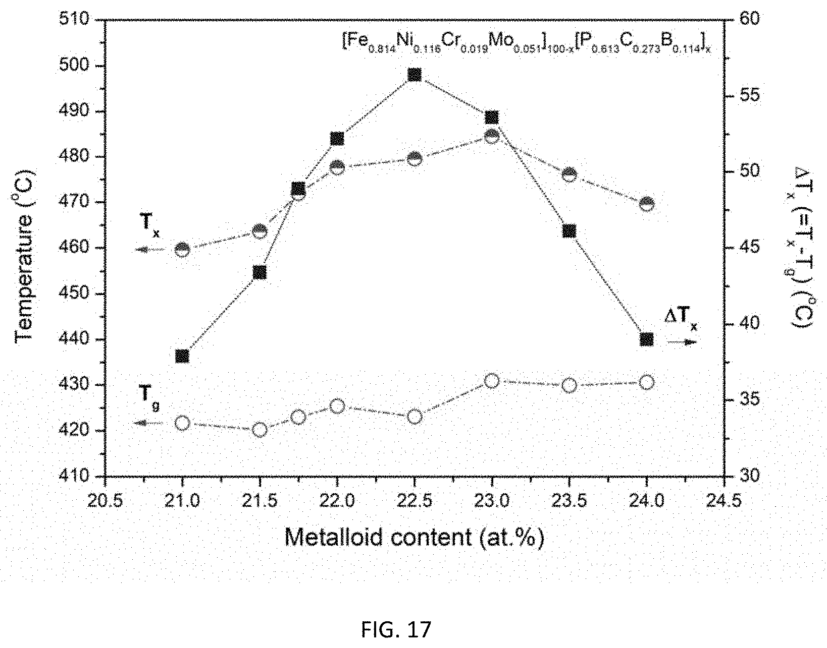
D00018

D00019

D00020

D00021

XML
uspto.report is an independent third-party trademark research tool that is not affiliated, endorsed, or sponsored by the United States Patent and Trademark Office (USPTO) or any other governmental organization. The information provided by uspto.report is based on publicly available data at the time of writing and is intended for informational purposes only.
While we strive to provide accurate and up-to-date information, we do not guarantee the accuracy, completeness, reliability, or suitability of the information displayed on this site. The use of this site is at your own risk. Any reliance you place on such information is therefore strictly at your own risk.
All official trademark data, including owner information, should be verified by visiting the official USPTO website at www.uspto.gov. This site is not intended to replace professional legal advice and should not be used as a substitute for consulting with a legal professional who is knowledgeable about trademark law.