Power Supply And Recharging Assembly And Method For An Electric Vehicle, And Electric Vehicle Comprising The Power Supply And Re
Zappaterra; Massimo ; et al.
U.S. patent application number 16/749676 was filed with the patent office on 2020-08-20 for power supply and recharging assembly and method for an electric vehicle, and electric vehicle comprising the power supply and re. The applicant listed for this patent is IVECO S.p.A.. Invention is credited to Alessandro Bernardini, Cristian Bertolotto, Giorgio Mantovani, Massimo Zappaterra.
| Application Number | 20200262302 16/749676 |
| Document ID | 20200262302 / US20200262302 |
| Family ID | 1000004823452 |
| Filed Date | 2020-08-20 |
| Patent Application | download [pdf] |


| United States Patent Application | 20200262302 |
| Kind Code | A1 |
| Zappaterra; Massimo ; et al. | August 20, 2020 |
POWER SUPPLY AND RECHARGING ASSEMBLY AND METHOD FOR AN ELECTRIC VEHICLE, AND ELECTRIC VEHICLE COMPRISING THE POWER SUPPLY AND RECHARING ASSEMBLY
Abstract
A recharging method and assembly to charge an electric vehicle comprising a battery pack including a plurality of storage batteries having a same nominal charge voltage, the battery pack being connectable to a recharging station adapted to provide a recharging voltage, which his greater than said nominal charge voltage. In an recharging mode of the battery pack, in which the recharging voltage deliverable by the recharging station is smaller than the sum of the nominal charge voltages of the plurality of storage batteries, the storage batteries are connected in parallel to one another, so as to recharge each battery with a recharging voltage equal to the nominal charge voltage. In a different recharging mode, in which the recharging voltage deliverable by the recharging station is equal to o greater than the sum of the nominal charge voltages of the plurality of storage batteries, the storage batteries in series to one another, so as to recharge the series of batteries with a recharging voltage greater than the nominal charge voltage.
| Inventors: | Zappaterra; Massimo; (Genova, IT) ; Bertolotto; Cristian; (Levanto (SP), IT) ; Mantovani; Giorgio; (Genova, IT) ; Bernardini; Alessandro; (Genova, IT) | ||||||||||
| Applicant: |
|
||||||||||
|---|---|---|---|---|---|---|---|---|---|---|---|
| Family ID: | 1000004823452 | ||||||||||
| Appl. No.: | 16/749676 | ||||||||||
| Filed: | January 22, 2020 |
| Current U.S. Class: | 1/1 |
| Current CPC Class: | B60L 53/30 20190201; B60L 53/53 20190201; B60L 53/16 20190201 |
| International Class: | B60L 53/16 20060101 B60L053/16; B60L 53/53 20060101 B60L053/53; B60L 53/30 20060101 B60L053/30 |
Foreign Application Data
| Date | Code | Application Number |
|---|---|---|
| Jan 24, 2019 | IT | 102019000001099 |
Claims
1. A method of recharging an electric vehicle (50) comprising a battery pack (2) including a plurality of storage batteries (2a, 2b, . . . , 2i, 2j) having a same nominal charge voltage, the battery pack (2) being connectable to a recharging station adapted to provide a recharging voltage, the method comprising the steps of: in a first recharging mode of the battery pack, in which the recharging voltage supplied by the recharging station is equal to said nominal charge voltage of the storage batteries, electrically connecting the storage batteries to the recharging station in parallel with each other, so as to recharge each storage battery with a recharging voltage equal to the nominal charge voltage; and in a second recharging mode of the battery pack, in which the recharging voltage supplied by the recharging station is equal to sum of the nominal charge voltages of the plurality of storage batteries, electrically connecting the storage batteries in series to each other, so as to recharge the series of storage batteries with a recharging voltage equal to sum of the nominal charge voltages.
2. The method according to claim 1, wherein the battery pack (2) includes a first and a second battery (2a, 2b ) having a same nominal charge voltage and each provided with a positive terminal (2a', 2b', . . . , 2i', 2j') and a negative terminal (2a'', 2b'', . . . , 2i'', 2j''); the first storage battery having the positive terminal coupled to the first power supply terminal (4a) via a first power supply switch (16a); and the second storage battery having the negative terminal coupled to the power supply terminal (4b) via a second power supply switch (16b); and in which the negative terminal of the first storage battery is coupled to the positive terminal of the second storage battery via a series switch (20), wherein electrically connecting the storage batteries in series comprises controlling the first and the second power supply switches (16a, 16b) and said series switch (20) in conduction.
3. A power supply and recharging assembly for an electric vehicle (50), comprising: a battery pack (2) including a plurality of storage batteries (2a, 2b, . . . , 2i, 2j) having a nominal charge voltage, the battery pack (2) being connectable to a recharging station adapted to provide a recharging voltage; a power bus (6) including a positive voltage line (6a) and a negative voltage line (6b); and a connector (4) having a first and a second power supply terminal (4a, 4b), configured to be connected to a recharging station that is adapted to supply said connector (4) with a recharging voltage; the storage batteries of said plurality of storage batteries being coupled to the power bus, in a parallel electrical configuration, via first switching means (12a, 12b, 14a, 14b); the storage batteries and the power bus being further coupled to the connector (4) via second switching means (16a, 16b); and the storage batteries being further coupled in series with each other via third switching means (20), wherein, in a first recharging mode of the battery pack, in which the recharging voltage supplied by the recharging station is equal to said nominal charge voltage of the storage batteries, the first, the second and the third switching means are controllable to electrically connect said storage batteries in parallel with each other, so as to recharge each storage battery with a recharging voltage equal to the nominal charge voltage; and in a second recharging mode of the battery pack, in which the recharging voltage supplied by the recharging station is equal to the sum of the nominal charge voltages of the plurality of storage batteries, the first, the second and the third switching means are controllable to electrically connect the storage batteries in series with each other, so as to recharge the series of storage batteries with a recharging voltage equal to the sum of the nominal charge voltages.
4. The power supply and recharging assembly according to claim 3, wherein said plurality of storage batteries includes a first and a second storage battery (2a, 2b) having said nominal charge voltage and each provided with a positive terminal (2a', 2b') and a negative terminal (2a'', 2b''); wherein said first switching means comprise: a first switch (12a) coupled between the positive terminal (2a') of the first storage battery (2a) and the positive voltage line (6a); a second switch (12b) connected between the negative terminal (2a'') of the first storage battery (2a) and the negative voltage line (6b); a third switch (14a) coupled between the positive terminal (2b') of the second storage battery (2b) and the positive voltage line (6a); and a fourth switch (14b) coupled between the negative terminal (2b'') of the second storage battery (2b) and a negative voltage line (6b); wherein said second switching means comprise: a fifth switch (16a) coupled between the first power supply terminal (4a) and the positive terminal (2a') of the first storage battery (2a) and also coupled to the positive voltage line (6a) via said first switch (12a); and a sixth switch (16b) coupled between the second power supply terminal (4b) and the negative terminal (2b'') of the second storage battery (2b) and further coupled to the negative voltage line (6b); and wherein said third switching means comprise a series switch (20) coupled between the negative terminal (2a'') of the first storage battery (2a) and the positive terminal (2b') of the second storage battery (2b), in the first recharging mode of the battery pack (2), the first, the second, the third, the fourth, the fifth and the sixth switches (12a-16b) are controllable in conduction and said series switch (20) is controllable in interdiction, to recharge the first and second storage batteries with a recharging voltage equal to the nominal charge voltage; and, in the second recharging mode of the battery pack, the first, the second, the third and the fourth switches (12a-14b) are controllable in interdiction, while said fifth and sixth switches (16a, 16b) and said series switch (20) are controllable in conducting, so as to recharge the series of storage batteries with a recharging voltage higher than the nominal charge voltage.
5. The power supply and recharging assembly according to claim 3, further comprising an electronic control unit (51) operatively coupled to the first, the second and the third switching means, and configured to operate the first, the second and the third switching means to implement the first recharging mode and, alternatively, the second recharging mode of the battery pack.
6. The power supply and recharging assembly according to claim 5, wherein the electronic control unit (51) is further configured to: acquire a maximum value for the recharging voltage deliverable by the recharging station; implement the first battery pack recharging mode if the recharging voltage is lower than the sum of the nominal charge voltages of the plurality of storage batteries; and implement the second battery pack recharging mode if the recharging voltage deliverable by the recharging station is equal to or greater than the sum of the nominal charge voltages of the plurality of storage batteries.
7. The power supply and recharging assembly according to claim 4, wherein said series switch (20) has a first and a second conduction terminal directly connected to the negative terminal of the first storage battery and, respectively, to the positive terminal of the second storage battery, said first conduction terminal of said series switch (20) being coupled to the negative voltage line (6b) via the first switch (12b), and said second conduction terminal of said series switch (20) being coupled to the positive voltage line (6a) via the third switch (14a).
8. The power supply and recharging assembly according to claim 7, wherein: in a vehicle key-off operating mode, the first, the second, the third, the fourth, the fifth and the sixth switches are controllable in interdiction, so that the battery pack (2) is disconnected from both the connector (4) and the power bus (6); and in a power delivery mode, the first, the second, the third and the fourth switches (12a-14b) are controllable in conduction state, while the fifth and the sixth switches (16a, 16b) and said series switch (20) are controllable tin interdiction state, so that the battery pack (2) is connected to the power bus (6) to supply power to the power bus.
9. The power supply and recharging assembly according to claim 3, wherein said recharging voltage supplied by the recharging station is between 800V and 1000V, said storage batteries being chosen so that the sum of the respective nominal charge voltages is equal to or less than said recharging voltage.
10. The power supply and recharging assembly according to claim 9, wherein said plurality is two and the nominal charge voltage is 400V.
11. A battery-powered electric vehicle (50), including a power supply and recharging assembly according to claim 1.
12. The electric vehicle (50) according to claim 11, further comprising an electrical load (10) electrically connected to the power supply and recharging assembly to receive a supply voltage from the battery pack (2).
Description
CROSS-REFERENCE TO RELATED APPLICATIONS
[0001] This patent application claims priority from Italian patent application no. 102019000001099 filed on Jan. 24, 2019, the entire disclosure of which is incorporated herein by reference.
STATEMENT RE: FEDERALLY SPONSORED RESEARCH/DEVELOPMENT
[0002] Not Applicable
TECHNICAL FIELD
[0003] The invention relates to a power supply and recharging assembly and method for an electric vehicle and to an electric vehicle comprising the power supply and recharging assembly.
KNOWN STATE OF THE ART
[0004] As it is known, in an electric vehicle (EV), an electric motor is the only source of energy used to drive the vehicle; in a hybrid vehicle, the electric motor is an auxiliary source of energy added to the internal combustion engine.
[0005] In an electric vehicle, the energy powering the electric motor is typically stored in one or more storage batteries or batteries. When the energy stored in the batteries decreases, they can be charged by connecting to vehicle to an external power supply source. Recharging stations (also known as "Electric Vehicle Supply Equipment"--EVSE), which are used to this purpose, act as interfaces between the vehicle and a power supply network, in order to supply a charging or recharging current to the batteries. Known recharging stations are configured to deliver recharging powers whose maximum value depends on the voltage and current supported both by the recharging stations themselves and by the electrical components used to provide the service (cables, contacts, etc.). More in particular, the maximum deliverable voltage depends on the features, performances and/or building specifications of the recharging station taken into account and on the maximum voltage supported by the batteries of the electric vehicle being charged.
[0006] Currently, recharging stations are available, which are enabled to provide voltages up to 1000 V (high-power recharging stations--HPC EVSE) and ensure small charging times. However, in order to fully exploit the voltage provided by these stations, the batteries mounted on board the vehicle must be designed to support voltages with a corresponding value. Batteries capable of supporting recharging voltages up to 800 V are available in the market, but are very expensive and, therefore, are not widely spread.
[0007] Therefore, there is a strong need to make use of high-power recharging stations, in particular capable of delivering energy at 800 V, though using, at the same time, batteries that are available in the market and are not too expensive.
[0008] The object of the invention is to fulfil the needs discussed above.
SUMMARY OF THE INVENTION
[0009] The aforesaid object is reached by means of a power supply and recharging assembly and method for an electric vehicle and of an electric vehicle comprising the power supply and recharging assembly, as set forth in the appended claims
BRIEF DESCRIPTION OF THE DRAWINGS
[0010] The invention will be best understood upon perusal of the following detailed description of a preferred embodiment, which is provided by way of non-limiting example, with reference to the accompanying drawings, wherein:
[0011] FIG. 1 shows a recharging circuit for the storage batteries of an electric vehicle according to an embodiment of the invention;
[0012] FIGS. 2 and 3 show respective recharging circuits for the storage batteries of an electric vehicle according to further embodiments of the invention;
[0013] FIG. 4 schematically shows an electric vehicle provided with the recharging circuit according to any one of the embodiments of FIGS. 1-3.
DETAILED DESCRIPTION OF THE INVENTION
[0014] FIG. 1 schematically shows a recharging circuit 1 to charge a battery pack 2 of an electric vehicle (which is schematically shown in FIG. 4). The battery pack 2 is operatively coupled to an electrical load 10 of the electric vehicle so as to supply the electric energy needed for the operation of the electrical load 10. The battery pack 2 includes a plurality of rechargeable storage batteries. A connector 4 (which is also known as "charging inlet") is fixed to the electric vehicle in a known manner and is provided with a first and a second power supply pins 4a and 4b, which are operatively coupled to the battery pack 2 and to a power bus 6 (Dc-link), which powers the electrical load 10. The power bus 6 comprises a positive voltage line (+) 6a and a negative voltage line (-) 6b.
[0015] The electrical load 10 includes, in a per se known manner which is not part of the subject-matter of the invention, at least one inverter, which is coupled to the electric motor 10 so as to generate a torque to move the vehicle. The electrical load 10 can also include further components or systems of the electric vehicle, which use, for their operation, the current flowing in the power bus 6 (for example, the air conditioning system, the lighting system, the infotainment system, etc.).
[0016] The battery pack 2 comprises, in the embodiment of FIG. 1, a first and a second storage batteries 2a, 2b, each having the same nominal charge voltage, which here, for example, is 400V. The first and the second storage batteries 2a, 2b are, for example, lithium-ion batteries or, in general, known electrochemical storage batteries.
[0017] The first storage battery 2a has a positive terminal 2a' (terminal +) coupled to the positive voltage line 6a and a negative terminal 2a'' (terminal -) coupled to the negative voltage line 6b.
[0018] A switch 12a is interposed between the positive terminal 2a' (terminal +) and the positive voltage line 6a. When the switch 12a is in an open state, the positive terminal 2a' is electrically disconnected from the positive voltage line 6a; when the switch 12a is in a closed state, the positive terminal 2a' is electrically connected to the positive voltage line 6a.
[0019] A switch 12b is interposed between the negative terminal 2a'' (terminal -) and the negative voltage line 6b.
[0020] When the switch 12b is in an open state, the negative terminal 2a'' is electrically disconnected from the negative voltage line 6b; when the switch 12b is in a closed state, the negative terminal 2a'' is electrically connected to the negative voltage line 6b.
[0021] Similarly, the second storage battery 2b has its own positive terminal 2b' (terminal +) coupled to the positive voltage line 6a and its own negative terminal 2b'' (terminal -) coupled to the negative voltage line 6b.
[0022] A switch 14a is interposed between the positive terminal 2b' (terminal +) and the positive voltage line 6a. When the switch 14a is in an open state, the positive terminal 2b' is electrically disconnected from the positive voltage line 6a; when the switch 14a is in a closed state, the positive terminal 2b' is electrically connected to the positive voltage line 6a.
[0023] A switch 14b is interposed between the negative terminal 2b'' (terminal -) and the negative voltage line 6b.
[0024] When the switch 14b is in an open state, the negative terminal 2b'' is electrically disconnected from the negative voltage line 6b; when the switch 14b is in a closed state, the negative terminal 2b'' is electrically connected to the negative voltage line 6b.
[0025] In FIG. 1, reference numeral 15 indicates an electric node between the positive terminal 2a' of the first storage battery 2a and the switch 12a (in particular, the node 15 coincides with the positive terminal 2a'). Furthermore, it is shown a further electric node 17 between the negative terminal 2b'' of the second storage battery 2b and the switch 14b (in particular, the node 17 coincides with the negative terminal 2b'').
[0026] The first power supply pin 4a of the charging inlet 4 is coupled, through a switch 16a, to the node 15. The second power supply pin 4b is coupled, through a switch 16b, to the node 17.
[0027] The switches 16a and 16b can be switched to an open state and to a closed state so as to electrically disconnect and connect, respectively, the power supply pins 4a, 4b from/to the nodes 15, 17.
[0028] Therefore, according to the operating diagram suggested herein, the first power supply pin 4a of the charging inlet 4 is coupled to the positive power supply line 6a by means of the switch 12a and the second power supply pin 4b of the charging inlet 4 is coupled to the negative power supply line 6b by means of the switch 14b.
[0029] According to an aspect of the invention, the negative terminal 2a'' of the first storage battery 2a is coupled to the positive terminal 2b' of the second storage battery 2b by means of a switch 20. The switch 20 can be switched to an open state so as to electrically disconnect the negative terminal 2a'' from the positive terminal 2b' and to a closed state so as to electrically connect the negative terminal 2a'' to the positive terminal 2b'.
[0030] As explained more in detail below, the switch 20 has the function, in an operating condition which is better discussed hereinafter, of electrically connecting the first and the second storage batteries 2a, 2b to one another in series.
[0031] In a non-limiting embodiment, the switches 12a, 12b, 14a, 14b, 16a, 16b and 20 are contactors, namely electric-mechanical devices, which are not manually operated and are adapted to stand currents in high-power conditions (in this case, amounting to hundreds of Volts, in particular up to 800 V). Alternatively, the switches 12a, 12b, 14a, 14b, 16a, 16b and 20 can be solid-state devices, chosen depending on the needs.
[0032] The switches 12a, 12b, 14a, 14b, 16a, 16b and 20 are operatively coupled to an electronic control unit (shown in FIG. 4 with reference number 51), which is configured to switch the switches 12a, 12b, 14a, 14b, 16a, 16b and 20 to an open and closed state in order to implement a plurality of operating modes described hereinafter.
[0033] In detail, the electronic control unit 51 is configured to control the switches 12a, 12b, 14a, 14b, 16a, 16b and 20 so as to implement a plurality of operating modes of the recharging circuit 1, among which there are, in particular: a rest mode (or "key-off" mode), a power supply mode, a first recharging mode and a second recharging mode.
[0034] In the key-off mode, the electric vehicle is not powered by means of the battery pack 2 and, at the same time, the battery pack 2 is not being charged (for example, when the electric vehicle is parked).
[0035] In the power supply mode, the electrical load 10 is powered by means of the battery pack 2 (for example, during the drive).
[0036] In the first and the second recharging modes, the batteries are charged using different values of recharging voltage.
[0037] The electronic control unit 51 can be the electronic control unit of the electric vehicle, properly configured, via software, to implement one or more of the aforesaid operating modes (in particular, the first recharging mode and the second recharging mode); alternatively, the electronic control unit 51 can be a further additional control unit beside the electronic control unit of the electric vehicle or a generic controller, properly configured and designed to implement one or more of the aforesaid operating modes (in particular, the first recharging mode and the second recharging mode).
[0038] More in detail, in the key-off mode, the switches 12a, 12b, 14a, 14b, 16a, 16b and, optionally, the switch 20 are controlled by the electronic control unit 51 so as to switch to an open state.
[0039] The following table schematically shows the state of the aforesaid switches in the key-off mode:
TABLE-US-00001 Switch 12a OPEN Switch 12b OPEN Switch 14a OPEN Switch 14b OPEN Switch 16a OPEN Switch 16b OPEN Switch 20 OPEN
[0040] Therefore, the batteries 2a and 2b are electrically disconnected both from the charging inlet 4 and from the power bus 6.
[0041] In the power supply mode, the switches 16a, 16b and 20 are controlled by the electronic control unit 51 so as to switch to an open state, whereas the switches 12a, 12b, 14a and 14b are controlled by the electronic control unit 51 so as to switch to a closed state.
[0042] The following table schematically shows the state of the aforesaid switches in the power supply mode:
TABLE-US-00002 Switch 12a CLOSED Switch 12b CLOSED Switch 14a CLOSED Switch 14b CLOSED Switch 16a OPEN Switch 16b OPEN Switch 20 OPEN
[0043] As a consequence, the batteries 2a, 2b are electrically connected in parallel to the power bus 6 and the electrical load 10 is powered by means of the voltage provided by the storage batteries 2a, 2b. As already mentioned above, in this embodiment, each storage battery 2a, 2b provides the power bus 6 with a nominal voltage of approximately 400V. Furthermore, the battery pack 2 is electrically disconnected from the charging inlet 4.
[0044] In the first recharging mode, the switch 20 is controlled by the electronic control unit 51 so as to switch to an open state, whereas the switches 16a, 16b, 12a, 12b, 14a and 14b are controlled by the electronic control unit 51 so as to switch to a closed state.
[0045] The following table schematically shows the state of the aforesaid switches in the first recharging mode:
TABLE-US-00003 Switch 12a CLOSED Switch 12b CLOSED Switch 14a CLOSED Switch 14b CLOSED Switch 16a CLOSED Switch 16b CLOSED Switch 20 OPEN
[0046] As a consequence, the first and the second storage batteries 2a, 2b are electrically connected to one another in parallel and are charged by means of the power supply voltage provided by the charging station through the charging inlet 4. In a known manner, during the first recharging mode, the electric vehicle communicates to the recharging station the maximum voltage limit supported by the battery pack 2, so as to protect the battery pack 2 from overvoltages. In this way, even though the known recharging station can supply voltages up to 1000V (more commonly 800V), the battery pack 2 is charged at the nominal charge voltage of the storage batteries 2a, 2b, without damages. Since the power bus 6 is powered, the electrical load 10 can be selectively disconnected from the power bus 6.
[0047] In the second recharging mode, the switches 16a, 16b and 20 are controlled by the electronic control unit 51 so as to switch to a closed state, whereas the switches 12a, 12b, 14a and 14b are controlled by the electronic control unit 51 so as to switch to an open state.
[0048] The following table schematically shows the state of the aforesaid switches in the second recharging mode:
TABLE-US-00004 Switch 12a OPEN Switch 12b OPEN Switch 14a OPEN Switch 14b OPEN Switch 16a CLOSED Switch 16b CLOSED Switch 20 CLOSED
[0049] As a consequence, the first and the second storage batteries 2a, 2b are electrically connected to one another in series and are charged by means of the power supply voltage provided by the charging station through the charging inlet 4.
[0050] During the first and the second recharging modes, the electric vehicle communicates to the recharging station, through the battery management system--BMS, the maximum voltage supported by the battery pack 2. The BMS communicates with the recharging station through high-level communication (e.g. PLC or WiFi or another communication mode), according to the IEC61851 and ISO 15118 standards. The BMS is also interfaced with the electronic control unit 51 and serves as communication interface between the latter and the recharging station.
[0051] As an alternative or in addition to the BMS, the VMU can carry out this interface function.
[0052] Since the storage batteries 2a, 2b are electrically connected to one another in series, the maximum voltage supported by the battery pack 2, in the second recharging mode, is greater than each one of the nominal voltages of the storage batteries 2a, 2b; in particular, the maximum voltage supported by the battery pack 2 is the result of the sum of the nominal charge voltages of the storage batteries 2a, 2b (hence, in this example, the maximum voltage supported by the battery pack 2 is 800V). In this way, the potentialities of the recharging station (for instance, power delivered) can be exploited to the utmost, charging the battery pack 2 at a voltage that is greater than the one of the recharging mode described above, thus reducing charging times.
[0053] Based on the information received from the BMS, depending on the voltage that can be delivered by the recharging station, the electronic control unit 51 controls the state of the switches 12a, 12b, 14a, 14b, 16a, 16b and 20, implementing one of the recharging modes of the battery pack 2 described above based on the electric features of the recharging station with which the recharging circuit 1 is interfaced. For example, the switches are controlled in accordance with the first recharging mode (batteries 2a, 2b in parallel) in order to charge the batteries 2a, 2b at 400V when the recharging station supports a maximum voltage of 400V, or in accordance with the second recharging mode (batteries 2a, 2b in series) in order to charge them at 800V when the recharging station supports a maximum voltage of 800V.
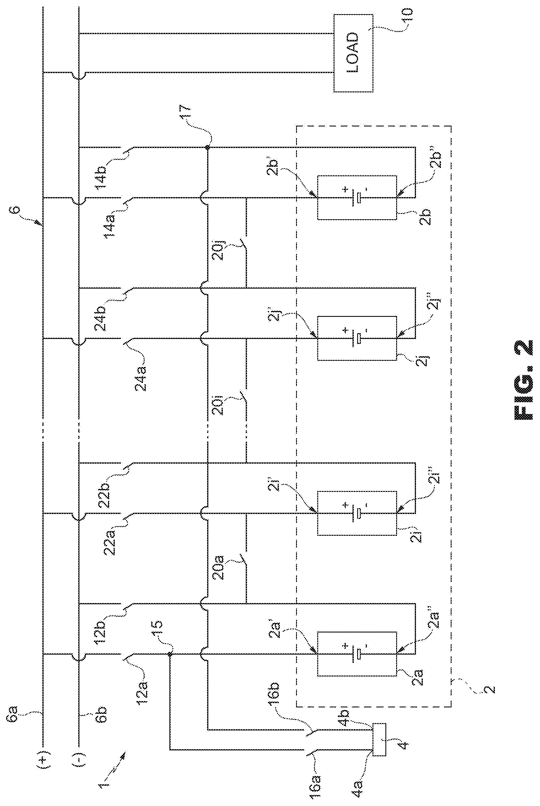
[0054] According to a further embodiment, which is shown in FIG. 2, the battery pack 2 comprises a plurality of storage batteries 2a, 2b, . . . , 2i, 2j. The elements of FIG. 2 that are the same as the ones of FIG. 1 are not further discussed and are indicated with the same reference numbers.
[0055] The nominal charge voltage of the storage batteries 2a-2j is chosen during the design phase based on the maximum voltage that can be delivered by the existing recharging stations and on the number of storage batteries to be installed on board the vehicle. In particular, the storage batteries 2a-2j have a same nominal charge voltage, which is chosen in such a way that the sum of the nominal charge voltages of the storage batteries 2a-2j (namely, the charge voltage at the ends of the battery pack 2 when the storage batteries 2a-2j are arranged in series with one another) is equal to or smaller than the voltage that can be delivered by the recharging station. In the diagram of FIG. 2, assuming--by way of example--that there is a total number of storage batteries 2a-2j of four and that the maximum voltage that can be delivered by the recharging station is 800V, each storage battery 2a-2j is chosen so as to have a nominal charge voltage of 200V.
[0056] In order to create the electric series connection of the storage batteries 2a-2j, there are switches 20a, 20i and 20j that electrically connect the opposite terminals of successive storage batteries of the electric series, similarly to what described above with reference to the switch 20, so as to obtain a series connection of all the storage batteries 2a-2j of the battery pack 2.
[0057] Furthermore, the switches 22a, 22b, 24a and 24b are shown, which have a function that is similar to the one described in FIG. 1 with reference to the switches 12a, 12b, 14a and 14b, respectively.
[0058] As a consequence, when the storage batteries 2a-2j are charged in accordance with the second recharging mode described above, the storage batteries 2a-2j are arranged in series with one another closing the switches 20a, . . . , 20i, 20j; therefore, they can be charged exploiting the maximum voltage delivered by the recharging station.
[0059] According to a further embodiment, which is shown in FIG. 3, the battery pack 2 of FIG. 1 is repeated k times. Therefore, with reference to FIG. 3, there are a plurality k of battery packs 2, . . . , k, with k being chosen based on the needs during the design phase. Each battery pack 2-k comprises a number of storage batteries chosen depending on what already discussed above with reference to FIGS. 1 and 2. The battery packs 2-k are electrically connected to the power bus 6 in parallel to one another and charged at the same time.
[0060] FIG. 4 schematically shows an electric vehicle 50 including: the charging inlet 4; the recharging circuit 1; the battery pack 2 (or a plurality of battery packs 2-k); the electronic control unit 51; and the electrical load 10. The electronic control unit 51, as already mentioned above, is operatively coupled to the switches 12a, 12b, 14a, 14b, 16a, 16b so as to implement the operating modes discussed above and, furthermore, is operatively coupled to the electrical load 10, for example in order to inhibit the drive of the electric vehicle stopping the operation of the electric motor during the first recharging mode; however, during the first recharging mode, the electronic control unit 51 can be configured to enable the operation of the air conditioning system and/or of the lighting system or of other systems or components of the electric vehicle other than the motor.
[0061] Owing to the above, the advantages of the subject-matter of the invention are evident.
[0062] In particular, the invention allows for a reduction of the time needed to charge the battery pack of the electric vehicle, with the possibility of adjusting to the features and performances of different recharging stations with which the electric vehicle can be interfaced during the use, using low-cost components. In particular, it is possible to use batteries with a nominal charge voltage of a few or some hundreds of Volts (for example, up to 400V), which can easily be found in the market and are relatively cheap, and, at the same time, it is possible to fully exploit the power that can be delivered by high-power recharging stations (HPC EVSE), which are designed to supply power with voltages up to 800-1000V.
[0063] Finally, the subject-matter of the invention can be subjected to changes and variants, which, though, do not go beyond the scope of protection set forth in the appended claims.
[0064] For example, one or more of the switches 12a, 12b, 14a, 14b, 16a, 16b and 20 can be arranged in a different way than the one shown in the figures, provided that they implement, when they are controlled accordingly, the operating modes provided for by the invention (in particular, the shift from the first to the second recharging mode depending on the voltage than can be delivered by the recharging station).
* * * * *
D00000
D00001
D00002
D00003
D00004
XML
uspto.report is an independent third-party trademark research tool that is not affiliated, endorsed, or sponsored by the United States Patent and Trademark Office (USPTO) or any other governmental organization. The information provided by uspto.report is based on publicly available data at the time of writing and is intended for informational purposes only.
While we strive to provide accurate and up-to-date information, we do not guarantee the accuracy, completeness, reliability, or suitability of the information displayed on this site. The use of this site is at your own risk. Any reliance you place on such information is therefore strictly at your own risk.
All official trademark data, including owner information, should be verified by visiting the official USPTO website at www.uspto.gov. This site is not intended to replace professional legal advice and should not be used as a substitute for consulting with a legal professional who is knowledgeable about trademark law.