Method For Dressing A Grinding Tool
Schweizer; Martin
U.S. patent application number 16/795917 was filed with the patent office on 2020-08-20 for method for dressing a grinding tool. The applicant listed for this patent is Klingelnberg AG. Invention is credited to Martin Schweizer.
| Application Number | 20200262028 16/795917 |
| Document ID | 20200262028 / US20200262028 |
| Family ID | 1000004701432 |
| Filed Date | 2020-08-20 |
| Patent Application | download [pdf] |


| United States Patent Application | 20200262028 |
| Kind Code | A1 |
| Schweizer; Martin | August 20, 2020 |
METHOD FOR DRESSING A GRINDING TOOL
Abstract
Method for dressing a grinding tool by means of a machine tool including dressing the grinding tool with a form dressing roller and generating a tool profile on the grinding tool by a contact between the rotating grinding tool and the rotating form dressing roller along a dressing path, and generating relative movement therebetween along the dressing path automatically with the aid of two or more NC axes, wherein during the relative movement along the dressing path and during the contact between the form dressing roller and the grinding tool, each of the NC axes has an axial velocity with an absolute value greater than zero, and none of these NC axes carries out a directional reversal or comes to a standstill.
| Inventors: | Schweizer; Martin; (Rastatt, DE) | ||||||||||
| Applicant: |
|
||||||||||
|---|---|---|---|---|---|---|---|---|---|---|---|
| Family ID: | 1000004701432 | ||||||||||
| Appl. No.: | 16/795917 | ||||||||||
| Filed: | February 20, 2020 |
| Current U.S. Class: | 1/1 |
| Current CPC Class: | B24B 53/062 20130101; B24B 53/085 20130101 |
| International Class: | B24B 53/085 20060101 B24B053/085; B24B 53/06 20060101 B24B053/06 |
Foreign Application Data
| Date | Code | Application Number |
|---|---|---|
| Feb 20, 2019 | EP | 19158274.1 |
Claims
1. A method comprising: mounting a dressable grinding tool in a machine tool; mounting a form dressing roller in the machine tool; rotating the grinding tool, rotating the dressing roller; and dressing the grinding tool with the form dressing roller, and generating a tool profile on the grinding tool by relative movement and contact between the rotating grinding tool and the rotating form dressing roller along a dressing path, wherein the method includes generating said relative movement along the dressing path automatically using at least two NC axes of the machine tool; and wherein, during the relative movement along the dressing path and during the contact between the form dressing roller and the grinding tool, each of the at least two NC axes defines an axial velocity with an absolute value greater than zero, and none of the at least two NC axes reverses direction or comes to a standstill.
2. The method according to claim 1, wherein the dressable grinding tool defines a dressable grinding wheel.
3. The method according to claim 2, wherein the grinding wheel defines a wheel profile defining a wheel profile cross section defining at least one local minimum and/or at least one local maximum, wherein the local minimum and/or local maximum are dressed in a continuous pass.
4. The method according to claim 1, wherein the grinding tool defines a dressable grinding worm.
5. The method according to claim 4, wherein the grinding tool defines a grinding worm defining a worm profile defining a worm profile cross section defining a plurality of local minima and/or local maxima, and wherein the dressing step includes dressing at least one local minimum and/or one local maximum in a continuous pass.
6. The method according to claim 1, wherein the grinding tool defines a profile defining a profile cross section defining at least one local minima and/or local maxima, and the step of generating relative movement includes generating two-dimensional axial movement using two of the at least two NC axes of the machine tool, and using a third of said at least two NC axes to define the dressing path as a three-dimensional dressing path.
7. The method according to claim 3, wherein the grinding tool defines a profile defining a profile cross section defining at least one local minima and/or local maxima, and the step of generating relative movement includes generating a two-dimensional axial movement using two of the at least two NC axes of the machine tool, and using a third of said at least two NC axes to define the dressing path as a three-dimensional dressing path.
8. The method according to claim 1, wherein one of the NC axes defines a linear axis.
9. The method according to claim 1, wherein one of the at least two NC axes defines a pivot axis or rotational axis.
10. The method according to claim 8, wherein one of the at least two NC axes defines a pivot axis or rotational axis.
11. The method according to claim 1, wherein at least one of the at least two NC axes define linear axes, wherein the axial velocity of each of the linear axes defines an absolute value of at least 1 .mu.m/s.
12. The method according to claim 11, wherein the absolute velocity is at least 10 .mu.m/s.
13. The method according to claim 1, wherein at least one of the at least two NC axes defines a rotational axis or a pivot axis, wherein each of the at least one of the at least two NC axes defining a rotational axis or pivot axis defines a rotational velocity or pivot velocity defining an absolute value of least 1*10.sup.-6.degree./s.
14. The method according to claim 13, wherein the absolute value of said rotational velocity or pivot velocity is at least 10*10.sup.-6.degree./s.
Description
CROSS-REFERENCE TO RELATED APPLICATIONS
[0001] This application claims the benefit under 35 U.S.C. .sctn. 119(e) to European patent application no. EP19158274.1 filed Feb. 20, 2019, which is hereby expressly incorporated by reference as part of the present disclosure.
FIELD OF THE INVENTION
[0002] The present disclosure generally relates to methods for dressing a grinding tool by means of a machine tool.
BACKGROUND
[0003] Dressing methods are used to sharpen and form grinding tools for the fine machining or hard fine machining of workpieces, such as gear wheels or the like.
[0004] To achieve a high precision with the least possible deviations from the required target geometry during the grinding of the workpiece to be machined using the dressed grinding tool, the dressing of the grinding tool preceding the grinding machining also has to take place with high accuracy. It is thus apparent that inadequate dimensional accuracy of the grinding tool geometry generated in the dressing procedure can be reflected directly in manufacturing deviations of the workpiece to be ground using the grinding tool.
[0005] During the dressing of the grinding tool, a relative movement takes place between the rotating grinding tool to be dressed and the rotating form dressing roller with the aid of NC axes of a machine tool. The dressing path, which describes the forming contact between the dressing roller and the grinding tool, is therefore traveled along with the aid of the NC axes. Errors in the axial movements of these NC axes therefore have a disadvantageous effect on the profile accuracy of the generated grinding tool profile, so that the machining accuracy of the workpiece to be machined using the grinding tool dressed in this manner is also negatively affected.
[0006] A frequently occurring deviation of the actual position from the target position in the axial movements of the NC axes arises if one or more of the participating NC axes has to be moved out of a standstill or with a directional reversal during the forming contact between the form dressing roller and the grinding wheel. In both cases, the affected NC axis has to be accelerated from a state of static friction into a state of sliding friction, so that a discontinuity in the time curve of the acting forces or a jerk arises (stick-slip effect).
[0007] One example of a known path error of a machine tool during the dressing procedure, which results from a directional reversal of an NC axis, is shown in FIG. 1. The NC axis in a Y direction (Y position) is implemented by a linear axis. The Y position shown in FIG. 1 therefore represents the movement route of this linear axis in millimeters. An NC axis in a Z direction (Z position) is implemented by a further linear axis. The Z position shown in FIG. 1 therefore represents the movement route of this further linear axis in millimeters.
[0008] The curve having the reference sign 1 represents the predetermined target route which is to be implemented to travel along a dressing path as the relative movement between a dressing roller and a grinding tool to be dressed by means of the linear axes in the Y direction and Z direction. The curve having the reference sign 2 describes the actual route which is actually implemented by the NC axes in the Y direction and Z direction.
[0009] The target route 1 has a local minimum 3, so that the linear axis of the Y direction has to carry out a direction change to travel along the target route 1. During the direction change, the linear axis of the Y direction comes to a short-term standstill and enters a state of static friction, so that proceeding from the local minimum 3, a growing deviation of the actual route 2 from the target route 1 can be seen, wherein the linear axis of the Y direction remains at a value of approximately 287.962 mm, while the linear axis of the Z direction continuously moves further. In this manner, a target-actual deviation of the Y position of approximately 0.004 mm results, the absolute value of which is illustrated by the double arrow 4.
[0010] It is self-evident that the disadvantageous effect of a directional reversal and/or a standstill of an NC axis, which is described with FIG. 1 for two linear axes, also exists for a standstill or a directional reversal of a pivot axis or rotational axis, which generates the travel along a dressing path in cooperation with one or more linear and/or pivot axes.
SUMMARY
[0011] Against this background, the present disclosure is based on the technical problem of specifying a method for dressing a grinding tool of the type mentioned at the outset, which in at least some embodiments does not have the above-described disadvantages or at least has them to a lesser extent and/or enables enhanced accuracy in the dressing of a grinding tool.
[0012] A method for dressing a grinding tool by means of a machine tool, has in at least some embodiments the following method steps:
[0013] providing a dressable grinding tool;
[0014] dressing the grinding tool by means of a form dressing roller,
[0015] wherein the tool profile to be generated on the grinding tool is formed by a contact between the rotating grinding tool and the rotating form dressing roller along a dressing path,
[0016] wherein a travel along the dressing path takes place automatically with the aid of two or more NC axes of the machine tool, which generate a relative movement between the rotating grinding tool and the rotating form dressing roller;
[0017] wherein during the travel along the dressing path and while the form dressing roller is in forming contact with the grinding tool, it is provided,
[0018] that each of the NC axes generating the relative movement between the rotating grinding tool and the rotating form dressing roller has an axial velocity, the absolute value of which is greater than zero, wherein none of these NC axes carries out a directional reversal or comes to a standstill.
[0019] Because none of the NC axes used for traveling along the dressing path comes to a standstill or carries out a directional reversal, a static friction state can be avoided for the respective NC axes and the deviations accompanying this. In at least some embodiments, the NC axes are exclusively moved in a state of sliding friction during the travel along the dressing path.
[0020] When reference is made in the present case to the NC axes which generate the travel along the dressing path and/or the relative movement between the rotating grinding tool and the rotating form dressing roller, in this case these are not the spindle drives which set the form dressing roller and the grinding tool into rotation about the respective tool or workpiece spindle axis thereof, respectively, but rather the NC axes which effectuate a displacement of a contact point or contact region in the forming contact between the grinding tool and the form dressing roller, for example, linear or pivot axes.
[0021] The NC axes mentioned can be linear axes arranged in accordance with Cartesian coordinates.
[0022] The NC axes can alternatively or additionally comprise linear axes which are oriented inclined and/or skewed in relation to one another.
[0023] The NC axes can comprise rotational and/or pivot axes.
[0024] The term "form dressing roller" means in the present case that the profile of the grinding tool to be dressed is generated kinematically, i.e., by a relative movement of the form dressing roller in relation to the grinding wheel, wherein in some embodiments there is not a linear contact but rather a point contact between the form dressing roller and the grinding tool. In contrast to a profile dressing roller, which specifies the profile of the grinding wheel in the linear contact solely by way of its profile shape, the form dressing roller mentioned here therefore does not comprise the profile of the grinding wheel as the negative form inherent to the dressing tool.
[0025] In at least some embodiments, one of the NC axes generating the relative movement between the rotating grinding tool and the rotating form dressing roller is a linear axis.
[0026] Alternatively or additionally, in at least some embodiments, one of the NC axes generating the relative movement between the rotating grinding tool and the rotating form dressing roller is a pivot axis or rotational axis.
[0027] The abbreviation "NC" stands in a known manner for "numeric control" and is to be understood in the scope of this text such that the relevant NC axis is movable with the aid of a machine controller and, in at least some embodiments, in the scope of a fully automatic program sequence.
[0028] When reference is made in the present case to an NC axis, in this case this is thus a unit for adjusting a relative position of the tool, the dressing roller here, in relation to the workpiece, the grinding tool here, or vice versa. Such an NC axis typically has a drive which can move a movable element over a predetermined angle and/or length range. For this purpose, the movable element is movably and/or rotatably mounted along a guide. The mounting or guiding of the relevant movable element can be embodied as hydrodynamic, hydrostatic, aerostatic, or rolling. A sliding carriage translationally movable along a slide rail can be mentioned as an example of a linear guide.
[0029] When reference is made in the present case to an NC axis which is a linear axis, this is thus, for example, a linear axis or linear unit having spindle drive, ballscrew drive, toothed belt drive, direct drive, or the like in this case.
[0030] When reference is made in the present case to an NC axis which is a rotational axis or pivot axis, this is thus, for example, in this case a rotational axis or pivot axis having electromotive, hydraulic, or pneumatic rotational drive, for example, rotational drives according to the steep thread principle or the toothed rack pinion principle.
[0031] Thus, for example, a spindle which bears the rotating dressing roller can be displaceable and/or pivotable by means of two or more linear axes and/or pivot axes in a workspace of the machine tool to execute a relative movement in relation to the grinding tool to be dressed. Furthermore, a spindle which bears the rotating grinding tool can alternatively or additionally be displaceable and/or pivotable by means of two or more linear axes and/or pivot axes in a workspace of the machine tool in order to execute a relative movement in relation to the dressing tool.
[0032] According to at least some embodiments of the method, the dressable grinding tool is a dressable grinding wheel. The accuracy in the dressing of the grinding wheel can accordingly be improved with the aid of the method.
[0033] According to at least some embodiments of the method, the grinding wheel has a grinding profile, the grinding profile cross section of which comprises at least one local minimum and/or at least one local maximum, wherein the local minimum and/or local maximum are dressed in a continuous pass. The shape or profile of the wheel profile cross section can be defined by a curve. This curve may have a local minimum and/or a local maximum.
[0034] When reference is made in the present case to a "continuous pass" this thus means that the dressing roller dresses the local minimum and/or local maximum of the grinding profile cross section of the grinding tool to be dressed without setting down or lifting off the dressing roller from the grinding tool in the continuous forming contact. The wheel profile cross section is therefore not dressed in a segmented manner, for example, in a rising region up to a maximum and a falling region which is dressed proceeding from the maximum in a second pass or a second infeed. Rather, in the present case the relevant local minimum and/or local maximum of the grinding profile cross section of the grinding tool to be dressed is passed over or dressed in a continuous contact between the dressing roller and the grinding tool.
[0035] When reference is made here to a cross section or profile cross section of a grinding tool, this is thus a plane of section which comprises the axis of rotation of the spindle of the grinding tool rotating around this axis of rotation.
[0036] During the dressing of profile cross sections having local maximum and/or local minimum, the problem outlined in FIG. 1 can exist, that one of the participating NC axes images the local minimum and/or local maximum of the profile cross section by a directional reversal. Such a profile cross section is intentionally generated without standstill or directional reversal of one of the NC axes, in order to keep the deviations from the target geometry of the wheel profile cross section to be generated small.
[0037] A directional reversal of one of the NC axes, which generates the relative movement between the rotating grinding tool and the rotating form dressing roller, can be avoided in that additional NC axes are used, the movements of which are superimposed to generate a dressing path.
[0038] If, for example, a wheel profile cross section of a grinding wheel having a local minimum or a depression is to be dressed, this can be achieved according to the prior art by a two-dimensional dressing path, which identically traces the profile cross section in the plane of section. In this case, the dressing path contains the local minimum of the profile cross section. If this dressing path is now traveled along using, for example, two linear axes arranged perpendicularly in relation to one another, one of these axes has to image the minimum of the dressing path by way of a directional reversal (cf. FIG. 1).
[0039] This can be prevented according to the present disclosure, for example, in that the dressing path of the grinding profile cross section, which is dressable two-dimensionally per se, is embodied three-dimensionally, so that in addition a movement transversely in relation to the above-described plane of section takes place during the dressing. The dressing path accordingly not only extends two-dimensionally in the radial and axial directions of the grinding wheel, but rather moreover also extends peripherally on the circumference around an angle range measured around the axis of rotation of the grinding wheel. The wheel profile discussed here having local minimum can thus be traveled along, for example, with the aid of three linear axes along a dressing path without local minimum, so that none of the three linear axes passes through a directional reversal or comes to a standstill.
[0040] In at least some embodiments, a profile of the grinding tool, the profile cross section of which comprises one or more local minima and/or local maxima, is dressable by a two-dimensional axial movement by means of two NC axes of a machine tool, wherein in addition a further third axis is used to carry out the dressing along a three-dimensional dressing path.
[0041] It is obvious that the above statements on the wheel profile cross section having local minimum and the participating linear axes are to be understood as examples and case constellations (configurations) having grinding tool profile cross sections having one or more local minima and/or one or more local maxima may similarly be specified and NC linear axes and/or NC pivot axes and/or NC rotational axes may be used in this case to enable a dressing of the profile of the grinding tool in a superimposed movement, wherein each of the NC axes generating the relative movement between the rotating grinding tool and the rotating form dressing roller has an axial velocity, the absolute value of which is greater than zero, wherein none of these NC axes carries out a directional reversal or comes to a standstill.
[0042] According to at least some embodiments, the grinding tool is a dressable grinding worm. The accuracy in the dressing of the grinding worm can accordingly be improved with the aid of the methods presented herein.
[0043] The grinding worm has in at least some embodiments a grinding worm profile, the worm profile cross section of which comprises a plurality of local minima and/or local maxima, wherein at least one local minimum and/or one local maximum are dressed in a continuous pass.
[0044] The statements made above relating to the grinding wheel on the significance of the continuous pass apply similarly here. Thus, minima and maxima of the relevant worm profile cross section are dressed, for example, without segmenting in the region of the minima or maxima, respectively.
[0045] In at least some embodiments, one or more of the NC axes are linear axes, wherein each of the linear axes generating the relative movement between the rotating grinding tool in the rotating form dressing roller has an axial velocity, the absolute value of which is greater than or equal to 1 .mu.m/s, for example, greater than or equal to 10 .mu.m/s. The respective linear axis is thus prevented from coming into a state of static friction during the travel along the dressing path and/or while the dressing roller is in forming contact with the grinding tool. It is self-evident that the relevant linear axis is exclusively moved in one direction--i.e., without directional reversal--during the dressing and/or the travel along the dressing path in forming contact.
[0046] In at least some embodiments, one or more of the NC axes are rotational axes or pivot axes, wherein each of the rotational axes or pivot axes generating the relative movement between the rotating grinding tool and the rotating form dressing roller has a rotational velocity or pivot velocity, the absolute value of which is greater than or equal to 1*10-6.degree./s, for example, greater than or equal to 10*10-6.degree./s.
[0047] At least some embodiments can be implemented, for example, with the aid of three linear axes, which are arranged in accordance with a Cartesian coordinate system.
[0048] At least some embodiments can be implemented with the aid of linear axes which are arranged inclined and/or skewed, i.e., for example, are not arranged perpendicular to one another.
[0049] Alternatively or additionally, pivot and/or rotational axes can be used to implement the teaching presented herein.
[0050] The relative arrangement of the respective NC axes or to what extent a relevant NC axis effectuates a rotational and/or translational relative movement is not decisive in each case here, but rather that the condition required according to the present disclosure is met, that during the travel down the dressing path and while the form dressing roller is in forming contact with the grinding tool, it is provided that each of the NC axes generating the relative movement between the rotating grinding tool and the rotating form dressing tool has an axial velocity, the absolute value of which is greater than zero, wherein none of these NC axes carries out a directional reversal or comes to a standstill.
[0051] This summary is not exhaustive of the scope of the present aspects and embodiments. Thus, while certain aspects and embodiments have been presented and/or outlined in this summary, it should be understood that the present aspects and embodiments are not limited to the aspects and embodiments in this summary. Indeed, other aspects and embodiments, which may be similar to and/or different from, the aspects and embodiments presented in this summary, will be apparent from the description, illustrations, and/or claims, which follow.
[0052] It should also be understood that any aspects and embodiments that are described in this summary and do not appear in the claims that follow are preserved for later presentation in this application or in one or more continuation patent applications.
BRIEF DESCRIPTION OF THE DRAWINGS
[0053] FIG. 1 schematically shows the fundamental problem of the present disclosure on the basis of two linear axes (prior art);
[0054] FIG. 2A schematically shows a grinding tool profile cross section of a grinding tool;
[0055] FIG. 2B schematically shows a side view of the grinding tool from FIG. 2A;
[0056] FIG. 2C schematically shows the grinding tool profile cross section from FIG. 2A having a dressing roller;
[0057] FIG. 2D schematically shows a side view of the grinding tool from FIG. 2C having the dressing roller in two positions;
[0058] FIG. 2E schematically shows a further side view of the grinding tool from FIG. 2C having the dressing roller in two positions;
[0059] FIG. 3 schematically shows a three-dimensional illustration of two dressing path profiles along a surface of the grinding tool.
DETAILED DESCRIPTION
[0060] Terms are used in conjunction with the present description which are also used in relevant publications and patents. However, it is to be noted that the use of these terms is merely to serve for better comprehension. The inventive concepts and the scope of protection of the claims are not to be restricted in the interpretation by the specific selection of the terms. The invention may be readily transferred to other term systems and/or technical fields. The terms are to be applied accordingly in other technical fields.
[0061] FIG. 1 has already been discussed at the outset to disclose a fundamental problem. In summary, a deviation 4 of the actual route 2 from the target route 1 can be avoided by avoiding a directional reversal of an NC axis--according to FIG. 1 the Y axis. An implementation of the solution according to at least some embodiments means that the relevant grinding tool is dressed in such a manner that the target route does not have a local minimum for any of the participating NC axes in the Y direction and Z direction, although the profile cross section of the grinding wheel to be dressed has such a local minimum. A solution to this problem is disclosed by way of example on the basis of FIGS. 2A-2E and FIG. 3.
[0062] FIG. 2A shows a grinding tool profile cross section 10 of a dressable grinding tool 12. The grinding tool profile cross section 10 shown here can be a portion of a part of a profile cross section of a grinding worm, the profile cross section of which extends in the positive and negative Z direction over a multiple of the portions shown in FIG. 2A. The grinding tool profile cross section 10 shown here can be a portion of a profile cross section of a grinding wheel, which also extends further in the positive and negative Z direction beyond the portion shown in FIG. 2A. The grinding tool profile cross section 10 shown here can be the profile cross section of a grinding wheel.
[0063] The coordinate axis (Z axis) identified with "Z" represents, on the one hand, a coordinate of the Cartesian coordinate system X, Y, Z shown in FIG. 2A. On the other hand, "Z" represents an NC linear axis of a machine tool 14, which enables a linear and/or translational movement of the grinding tool 12 along the coordinate direction "Z". This applies similarly to the axes X and Y, so that the Cartesian coordinate system X, Y, Z is not to be understood solely as a virtual reference system, but rather is spanned by three NC linear axes X, Y, Z oriented perpendicularly to one another.
[0064] The grinding tool profile cross section has a local minimum 16, which is illustrated in the side view according to FIG. 2B by the dashed circular line.
[0065] If this grinding profile 10 is now to be dressed using a form dressing roller 18 according to FIG. 2C, the form dressing roller 18 is typically moved two-dimensionally, i.e., exclusively within the Y-Z plane spanned by the Y axis and Z axis, specifically from a first contact point 20, toward a second contact point 22 located in the minimum 16, up to the contact point 24. The dressing path thus resulting, which is indicated by the hollow arrows, therefore identically images the profile cross section of the grinding tool 12 in the Y-Z plane. The linear axis Y passes through the described, disadvantageous directional reversal. The dressing path represented by the hollow arrows and contact points 20, 22, 24 is therefore not according to disclosed methods.
[0066] It is self-evident that the described dressing path represents a continuous pass along the profile of the grinding tool 12 and the contact points 20, 22, 24 are solely used as support points to illustrate the course of the continuous dressing path. The relative movement could alternatively extend proceeding from the contact point 24 via the contact point 22 toward the contact point 20.
[0067] A three-dimensional dressing path 26 is now used to dress the grinding tool 12.
[0068] For this purpose, a movement in the X direction is additionally superimposed on the movement in the Y direction and Z direction. In this case, a dressing path 26, which is represented by the solid arrows and the contact points 28, 30, 32, does not comprise a local minimum. The dressing path can therefore be traveled along continuously without directional reversal and standstill of one of the linear axes X, Y, Z, wherein nonetheless the local minimum of the profile cross section 10 is dressed in a continuous pass.
[0069] In other words, the form dressing roller 18 is additionally moved along a profile of the grinding wheel R(Z) in the circumferential direction of the grinding tool, as indicated by the angle .alpha..
[0070] A method for dressing the grinding tool 12 by means of the machine tool 14 is therefore carried out, having the following method steps.
[0071] Providing the dressable grinding tool 12; dressing the grinding tool 12 by means of the form dressing roller 18, wherein the tool profile 10 to be generated on the grinding tool 12 is formed by a contact between the rotating grinding tool 12 and the rotating form dressing roller 18 along a dressing path 26, wherein a travel along the dressing path 26 takes place automatically with the aid of three NC axes X, Y, Z of the machine tool 14, which generate a relative movement between the rotating grinding tool 12 and the rotating form dressing roller 18; and wherein it is provided during the travel along the dressing path 26 and while the form dressing roller 18 is in forming contact with the grinding tool 12 that each of the NC axes X, Y, Z generating the relative movement between the rotating grinding tool 12 and the rotating form dressing roller 18 has an axial velocity, the absolute value of which is greater than zero, wherein none of these NC axes X, Y, Z carries out a directional reversal or comes to a standstill.
[0072] FIG. 2E illustrates three positions of the form dressing roller 18, which the dressing path 26 assumes in the continuous forming contact with the grinding tool in an overview illustration.
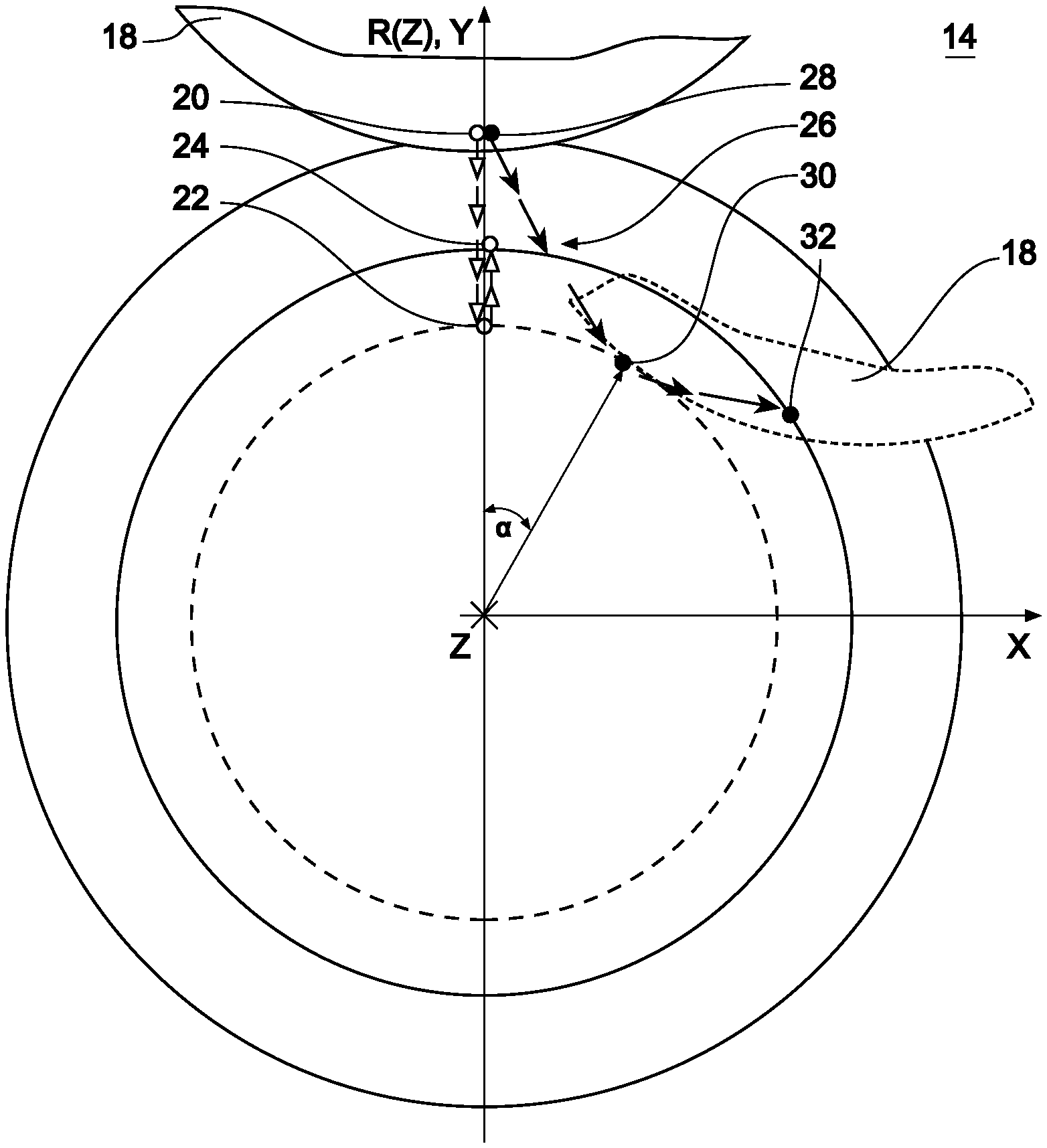
[0073] A comparison of a two-dimensional dressing path and the three-dimensional dressing path according to disclosed methods is shown in FIG. 3. The form dressing roller is not shown in FIG. 3 to improve the comprehensibility.
[0074] The hollow circles and arrows again represent a two-dimensional dressing path along the shaded surface of the grinding tool 12 to be dressed and the solid circles and arrows represent the dressing path for carrying out methods disclosed herein. R(z) is the radius of the grinding tool.
[0075] To illustrate the required movement routes of the linear axes X, Y, Z for the two-dimensional and the three-dimensional dressing path, the dressing paths have been projected on the Y-Z plane and the X-Z plane. It is apparent that the Y axis for the two-dimensional dressing path has to carry out a directional reversal to approach point 24 from the point 22. Furthermore, it is recognizable that no movement of the X axis is required for the two-dimensional dressing path. The profile of the grinding tool 12 is therefore dressable in a two-dimensional movement.
[0076] According to at least some embodiments, the dressing path 26 is selected according to the filled circles 28, 30, 32, wherein the dressing path 26 does not comprise a local minimum in its projection on the Y-Z plane and the X-Z plane. Each of the participating linear axes X, Y, Z is therefore exclusively moved in one direction, so that the dressing path 26 is traveled along without standstill or directional change of one of the NC axes X, Y, Z generating the relative movement between the form dressing roller and the grinding tool.
[0077] Therefore, the following condition can be established to determine a dressing path according "DY/DZ<=0 and DX/DZ>=0":
[0078] as long as DR/DZ<=0: X=0, Y(Z)=R(Z), Z=Z(T), and YMIN=Min(Y(Z));
[0079] if DR/DZ>0: X(Z)=SQRT(R.sup.2(Z)-YMIN.sup.2), Y(Z)=YMIN, Z=Z(T), wherein T corresponds to the processing time, so that Z functions as a guide axis for the synchronization of the participating NC axes.
[0080] The arrangement of three linear axes X, Y, Z corresponding to a Cartesian coordinate system is to be understood solely as an example and is used to illustrate the fundamental principle of the invention.
[0081] According to at least some embodiments, the method can be implemented with the aid of linear axes which are arranged inclined and/or skewed in relation to one another, i.e., for example, are not arranged perpendicularly to one another. Alternatively or additionally, pivot and/or rotational axes can be used.
[0082] In this case, the relative arrangement of the respective NC axis or to what extent the relevant NC axis effectuates a rotational and/or translational relative movement is not decisive, but rather that the condition required is met that during the travel along the dressing path and while the form dressing roller is in forming contact with the grinding tool, it is provided that each of the NC axes generating the relative movement between the rotating grinding tool and the rotating form dressing roller has an axial velocity, the absolute value of which is greater than zero, wherein none of these NC axes carries out a directional reversal or comes to a standstill.
[0083] While the above describes certain embodiments, those skilled in the art should understand that the foregoing description is not intended to limit the spirit or scope of the present disclosure. It should also be understood that the embodiments of the present disclosure described herein are merely exemplary and that a person skilled in the art may make any variations and modification without departing from the spirit and scope of the disclosure. All such variations and modifications, including those discussed above, are intended to be included within the scope of the disclosure.
* * * * *
D00000
D00001
D00002
D00003
D00004
D00005
XML
uspto.report is an independent third-party trademark research tool that is not affiliated, endorsed, or sponsored by the United States Patent and Trademark Office (USPTO) or any other governmental organization. The information provided by uspto.report is based on publicly available data at the time of writing and is intended for informational purposes only.
While we strive to provide accurate and up-to-date information, we do not guarantee the accuracy, completeness, reliability, or suitability of the information displayed on this site. The use of this site is at your own risk. Any reliance you place on such information is therefore strictly at your own risk.
All official trademark data, including owner information, should be verified by visiting the official USPTO website at www.uspto.gov. This site is not intended to replace professional legal advice and should not be used as a substitute for consulting with a legal professional who is knowledgeable about trademark law.