Hydrophilic Skirt For Paravalvular Leak Mitigation And Fit And Apposition Optimization For Prosthetic Heart Valve Implants
Kumar; Saravana B. ; et al.
U.S. patent application number 16/787792 was filed with the patent office on 2020-08-20 for hydrophilic skirt for paravalvular leak mitigation and fit and apposition optimization for prosthetic heart valve implants. The applicant listed for this patent is 4C Medical Technologies, Inc.. Invention is credited to Saravana B. Kumar, Jeffrey R. Stone.
| Application Number | 20200261219 16/787792 |
| Document ID | 20200261219 / US20200261219 |
| Family ID | 1000004762066 |
| Filed Date | 2020-08-20 |
| Patent Application | download [pdf] |


| United States Patent Application | 20200261219 |
| Kind Code | A1 |
| Kumar; Saravana B. ; et al. | August 20, 2020 |
HYDROPHILIC SKIRT FOR PARAVALVULAR LEAK MITIGATION AND FIT AND APPOSITION OPTIMIZATION FOR PROSTHETIC HEART VALVE IMPLANTS
Abstract
The present invention provides a prosthetic heart valve device with improved fit, apposition and/or paravalvular leakage mitigation. Thus, the prosthetic device comprises an anchoring structure for supporting prosthetic valve leaflets, wherein the anchoring structure comprises and/or is formed at least partially from a hydrophilic material designed to swell when contacted by the water solute in the patient's blood. Locating the hydrophilic material to provide swelling to improve the fit and/or apposition of the device to the patient's tissues results in, inter alia, improved paravalvular leakage mitigation. Some of the methods and mechanisms described herein may also be used to provide a seal against the septal hole created during transseptal delivery of the device.
| Inventors: | Kumar; Saravana B.; (Minnetonka, MN) ; Stone; Jeffrey R.; (Minnetonka, MN) | ||||||||||
| Applicant: |
|
||||||||||
|---|---|---|---|---|---|---|---|---|---|---|---|
| Family ID: | 1000004762066 | ||||||||||
| Appl. No.: | 16/787792 | ||||||||||
| Filed: | February 11, 2020 |
Related U.S. Patent Documents
| Application Number | Filing Date | Patent Number | ||
|---|---|---|---|---|
| 62805662 | Feb 14, 2019 | |||
| Current U.S. Class: | 1/1 |
| Current CPC Class: | A61F 2/2466 20130101; A61B 17/0057 20130101; A61F 2210/0076 20130101; A61B 2017/00632 20130101; A61F 2250/0031 20130101; A61F 2/246 20130101; A61F 2/2487 20130101; A61F 2/2418 20130101; A61F 2/2409 20130101; A61F 2210/0061 20130101 |
| International Class: | A61F 2/24 20060101 A61F002/24; A61B 17/00 20060101 A61B017/00 |
Claims
1. A device for expanded implantation into a patient's heart chamber, comprising: an expandable anchoring structure comprising an outer surface; a base section; a valve support adapted for supporting at least one prosthetic valve, and a skirt of single layered material operatively attached to a portion of the outer surface of the anchoring structure and wherein the skirt comprises hydrophilic material that is integrated into, or coated onto, the single layered material of the skirt.
2. The device of claim 1, wherein the hydrophilic material is coated onto an outer surface of the single layered material of the skirt.
3. The device of claim 1, wherein the hydrophilic material is overcoated with a thin film of material that is biodegradeable, dissolvable, bioerodable and/or bioabsorbable when exposed to liquid to enable subsequent exposure of the hydrophilic material to the liquid.
4. The device of claim 1, wherein the hydrophilic material is encased in nanoparticles that are integrated into, or coated onto, the single layered material of the skirt, and wherein the nanoparticles are biodegradeable, dissolvable, bioerodable and/or bioabsorbable when exposed to liquid to enable subsequent exposure of the hydrophilic material to the liquid.
5. The device of claim 1, wherein at least a portion of the skirt comprises two layers of material, wherein at least one pocket is defined between the two layers of material, and wherein the hydrophilic material is disposed within the at least one pocket of the skirt.
6. The device of claim 5, wherein the hydrophilic material is encased in nanoparticles, and wherein the nanoparticle is breakable, biodegradeable, dissolvable, bioerodable and/or bioabsorbable when exposed to liquid to enable subsequent exposure of the hydrophilic material to the liquid.
7. The device of claim 1, wherein the hydrophilic material comprises at least one of a hydrophilic polymer, a hydrophilic metal and/or hydrophilic hydrogel.
8. The device of claim 1, wherein the hydrophilic material is positioned to seal against and/or within the left atrial appendage when the device is implanted into the left atrium.
9. The device of claim 5, wherein the hydrophilic material is positioned to seal against and/or within the left atrial appendage when the device is implanted into the left atrium.
10. The device of claim 1, further comprising at least one ridge, flap or ring operatively attached to the skirt and comprising hydrophilic material.
11. The device of claim 10, wherein the at least one ridge, flap or ring is adapted to seal against or within the left atrial appendage.
12. The device of claim 1, wherein the device is adapted for use as a prosthetic heart valve for one or more of the group consisting of: the mitral valve, tricuspid valve, aortic valve and/or pulmonary valves.
13. A device for expanded implantation within a heart chamber comprising: an expandable anchoring structure comprising a base section and an outer surface; and wherein at least a portion of the anchoring structure comprises a hydrophilic material.
14. The device of claim 13, wherein the hydrophilic material is overcoated with a thin biodegradeable, dissolvable, bioerodable and/or bioabsorbable thin film.
15. The device of claim 13, wherein the hydrophilic material comprises a hydrophilic metal.
16. The device of claim 13, further comprising a valve support operatively connected with the base section and adapted to support at least one prosthetic valve, wherein the base section comprises a hydrophilic metal.
17. The device of 16, wherein the base section comprises a stent formed of struts and wherein at least some of the struts comprise a hydrophilic metal.
18. The device of claim 13, further comprising a valve support integrally formed from the base section and adapted to support at least one prosthetic valve, wherein the base section comprises a hydrophilic metal.
19. The device of claim 18, wherein the base section comprises a stent formed of struts and wherein at least some of the struts comprise a hydrophilic metal.
20. The device of claim 18, further comprising a skirt of single layered material operatively attached to a portion of the outer surface of the anchoring structure.
21. The device of claim 20, wherein the skirt comprises hydrophilic material that is integrated into, or coated onto, the single layered material of the skirt.
22. The device of claim 21, wherein the hydrophilic material is coated onto an outer surface of the single layered material of the skirt.
23. The device of claim 21, wherein the hydrophilic material is overcoated with a thin film of material that is biodegradeable, dissolvable, bioerodable and/or bioabsorbable when exposed to liquid to enable subsequent exposure of the hydrophilic material to the liquid.
24. The device of claim 21, wherein the hydrophilic material is encased in nanoparticles that are integrated into, or coated onto, the single layered material of the skirt, and wherein the nanoparticles are biodegradeable, dissolvable, bioerodable and/or bioabsorbable when exposed to liquid to enable subsequent exposure of the hydrophilic material to the liquid.
25. The device of claim 13, further comprising a skirt of material operatively attached to a portion of the outer surface of the anchoring structure and wherein at least a portion of the skirt comprises two layers of material, wherein at least one pocket is defined between the two layers of material, and wherein the hydrophilic material is disposed within the at least one pocket of the skirt.
26. The device of claim 25, wherein the hydrophilic material is encased in nanoparticles, and wherein the nanoparticle is breakable, biodegradeable, dissolvable, bioerodable and/or bioabsorbable when exposed to liquid to enable subsequent exposure of the hydrophilic material to the liquid.
27. The device of claim 25, wherein the at least one pocket is positioned to seal against and/or within the left atrial appendage when the device is implanted into the left atrium.
28. The device of claim 13, wherein the device is adapted for use as a prosthetic heart valve for one or more of the group consisting of: the mitral valve, tricuspid valve, aortic valve and/or pulmonary valves.
29. (canceled)
30. A device for expanded implantation within a heart chamber comprising: an expandable anchoring structure comprising a base section and an outer surface; a skirt of material operatively attached to a portion of the outer surface of the anchoring structure and wherein at least a portion of the skirt comprises two layers of material, wherein at least one pocket is defined between the two layers of material, and wherein the hydrophilic material is disposed within the at least one pocket of the skirt.
31. The device of claim 30, wherein the hydrophilic material is encased in nanoparticles, and wherein the nanoparticle is breakable, biodegradeable, dissolvable, bioerodable and/or bioabsorbable when exposed to liquid to enable subsequent exposure of the hydrophilic material to the liquid.
32. The device of claim 30, wherein at least one pockets is positioned to mitigate paravalvular leakage.
33. The device of claim 30, wherein at least one pockets is positioned to seal against and/or within the left atrial appendage when the device is implanted into the left atrium.
34. The device of claim 30, wherein when the device is delivered transseptally into a left atrium, at least one pocket is positioned to seal a delivery hole located in the septum between the right and left atria.
35. The device of claim 30, wherein the device is adapted for use as a prosthetic heart valve for one or more of the group consisting of: the mitral valve, tricuspid valve, aortic valve and/or pulmonary valves.
36. (canceled)
Description
CROSS-REFERENCE TO RELATED APPLICATIONS
[0001] This application claims the benefit of U.S. Provisional Application Serial No. 62/805662, filed Sep. 4, 2018 and entitled HYDROPHILIC SHIRT FOR PARAVALVULAR LEAK MITIGATION AND FIT AND APPOSITION OPTIMIZATION FOR PROSTHETIC HEART VALVE IMPLANTS, the entire contents of which are incorporated herein by reference.
STATEMENT REGARDING FEDERALLY SPONSORED RESEARCH OR DEVELOPMENT
[0002] Not Applicable
BACKGROUND OF THE INVENTION
Field of the Invention
[0003] The invention relates to devices and methods for implanting devices within a heart chamber. More specifically, the invention relates to improved mitigation of paravalvular leakage, apposition and fit of the implanted anchoring structure with the heart chamber and related anatomy and closure of the septal hole when trans-septal delivery is used.
Description of the Related Art
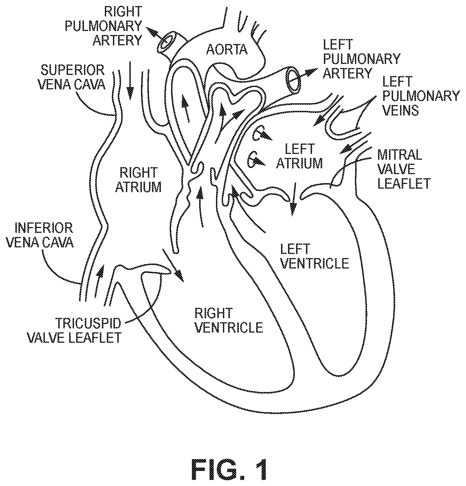
[0004] The human heart comprises four chambers and four heart valves that assist in the forward (antegrade) flow of blood through the heart. The chambers include the left atrium, left ventricle, right atrium and left ventricle. The four heart valves include the mitral valve, the tricuspid valve, the aortic valve and the pulmonary valve. See generally FIG. 1.
[0005] The mitral valve is located between the left atrium and left ventricle and helps control the flow of blood from the left atrium to the left ventricle by acting as a one-way valve to prevent backflow into the left atrium. Similarly, the tricuspid valve is located between the right atrium and the right ventricle, while the aortic valve and the pulmonary valve are semilunar valves located in arteries flowing blood away from the heart. The valves are all one-way valves, with leaflets that open to allow forward (antegrade) blood flow. The normally functioning valve leaflets close under the pressure exerted by reverse blood to prevent backflow (retrograde) of the blood into the chamber it just flowed out of. For example, the mitral valve when working properly provides a one-way valving between the left atrium and the left ventricle, opening to allow antegrade flow from the left atrium to the left ventricle and closing to prevent retrograde flow from the left ventricle into the left atrium. This retrograde flow, when present, is known as mitral regurgitation or mitral valve regurgitation.
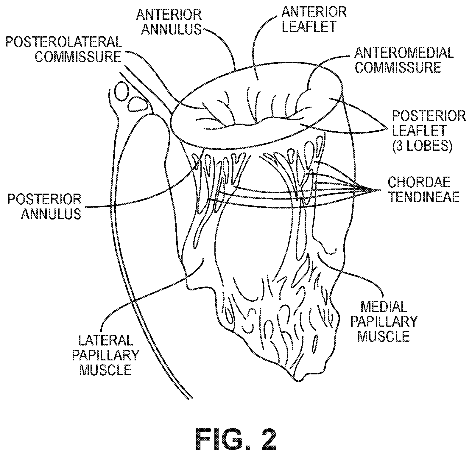
[0006] FIG. 2 illustrates the relationship between the left atrium, annulus, chordae tendineae and the left ventricle relative to the mitral valve leaflets. As is shown, the upper surface of the annulus forms at least a portion of the floor or lower surface of the left atrial chamber, so that for purposes of description herein, the upper surface of the annulus is defined as marking the lower boundary of the left atrial chamber.
[0007] Native heart valves may be, or become, dysfunctional for a variety of reasons and/or conditions including but not limited to disease, trauma, congenital malformations, and aging. These types of conditions may cause the valve structure to fail to close properly resulting in regurgitant retrograde flow of blood from the left ventricle to the left atrium in the case of a mitral valve failure. FIG. 3 illustrates regurgitant blood flow with an exemplary dysfunctional mitral valve.
[0008] Mitral valve regurgitation is a specific problem resulting from a dysfunctional mitral valve that allows at least some retrograde blood flow back into the left atrium from the right atrium. In some cases, the dysfunction results from mitral valve leaflet(s) that prolapse up into the left atrial chamber, i.e., above the upper surface of the annulus as designated by line or plane A, instead of connecting or coapting to block retrograde flow. This backflow of blood places a burden on the left ventricle with a volume load that may lead to a series of left ventricular compensatory adaptations and adjustments, including remodeling of the ventricular chamber size and shape, that vary considerably during the prolonged clinical course of mitral regurgitation.
[0009] Regurgitation can be a problem with native heart valves generally, including tricuspid, aortic and pulmonary valves as well as mitral valves.
[0010] Native heart valves generally, e.g., mitral valves, therefore, may require functional repair and/or assistance, including a partial or complete replacement. Such intervention may take several forms including open heart surgery and open heart implantation of a replacement heart valve. See e.g., U.S. Pat. No. 4,106,129 (Carpentier), for a procedure that is highly invasive, fraught with patient risks, and requiring not only an extended hospitalization but also a highly painful recovery period.
[0011] Less invasive methods and devices for replacing a dysfunctional heart valve are also known and involve percutaneous access and catheter-facilitated delivery of the replacement valve. Most of these solutions involve a replacement heart valve attached to a structural support such as a stent, commonly known in the art, or other form of wire network designed to expand upon release from a delivery catheter. See, e.g., U.S. Pat. No. 3,657,744 (Ersek); U.S. Pat. No. 5,411,552 (Andersen). The self-expansion variants of the supporting stent assist in positioning the valve, and holding the expanded device in position, within the subject heart chamber or vessel. This self-expanded form also presents problems when, as is often the case, the device is not properly positioned in the first positioning attempt and, therefore, must be recaptured and positionally adjusted. This recapturing process in the case of a fully, or even partially, expanded device requires re-collapsing the device to a point that allows the operator to retract the collapsed device back into a delivery sheath or catheter, adjust the inbound position for the device and then re-expand to the proper position by redeploying the positionally-adjusted device distally out of the delivery sheath or catheter. Collapsing the already expanded device is difficult because the expanded stent or wire network is generally designed to achieve the expanded state which also resists contractive or collapsing forces.
[0012] Besides the open heart surgical approach discussed above, gaining access to the valve of interest is achieved percutaneously via one of at least the following known access routes: transapical; transfemoral; transatrial; and trans septal delivery techniques.
[0013] Transseptal delivery involves creating an access hole in the septum between the right and left atria. Once the delivery and implantation of the prosthetic heart valve device is achieved, the septal hole either remains open to heal on its own, or is sealed at least partially. However, known sealing techniques require additional tools and manipulation to achieve the at least partial closure. A more efficient and effective septal closure mechanism would be desirable.
[0014] Generally, the art is focused on systems and methods that, using one of the above-described known access routes, allow a partial delivery of the collapsed valve device, wherein one end of the device is released from a delivery sheath or catheter and expanded for an initial positioning followed by full release and expansion when proper positioning is achieved. See, e.g., U.S. Pat. No. 8,852,271 (Murray, III); U.S. Pat. No. 8,747,459 (Nguyen); U.S. Pat. No. 8,814,931 (Wang); U.S. Pat. No. 9,402,720 (Richter); U.S. Pat. No. 8,986,372 (Murray, III); and U.S. Pat. No. 9,277,991 (Salahieh); and U.S. Pat. Pub. Nos. 2015/0272731 (Racchini); and 2016/0235531 (Ciobanu).
[0015] In addition, all known prosthetic heart valves are intended for full replacement of the native heart valve. Therefore, these replacement heart valves, and/or anchoring or tethering structures, physically extend out of the left atrial chamber, in the case of mitral valves, and engage the inner annulus and/or valve leaflets, in many cases pinning the native leaflets against the walls of the inner annulus, thereby permanently eliminating all remaining functionality of the native valve and making the patient completely reliant on the replacement valve. In other cases, the anchoring structures extend into the left ventricle and may anchor into the left ventricle wall tissue and/or the sub-annular surface at the top of the left ventricle. Others may comprise a presence in, or engagement with, a pulmonary artery.
[0016] Obviously, there will be cases when native valve has lost virtually complete functionality before the interventional implantation procedure. In this case the preferred solution will comprise an implant that does not extent outside of, e.g., the left atrium, and that functions to completely replace the native valve function. However, in many other cases, the native valve remains functional to an extent and may, or may not, continue to lose functionality after the implantation procedure. A preferred solution in this case comprises delivery and implantation of a valve device that will function both as a supplemental or augmentation valve without damaging the native leaflets in order to retain native valve leaflet functionality as long as present, while also being fully capable of replacing the native function of a valve that slowly loses most or all of its functionality post-implantation of the prosthetic valve.
[0017] In all cases, including two-chamber solutions, paravalvular leakage (PVL) may develop as a result of insufficient sealing or apposition of the prosthetic valve device and the native chamber tissue, including but not limited to annular sealing. In the case of the exemplary mitral valve, PVL results in a retrograde leak of blood from the left ventricle to the left atrium, reducing the efficiency of the heart. Lack of sealing apposition may occur for several reasons.
[0018] For example, patients may have at least some calcification in the heart chamber, particularly in the annular surface which works to reduce compliance of that calcified tissue. This reduced compliance reduces the ability of the tissue and the prosthetic heart valve device to seal together on implantation, leaving gaps between tissue and device. The mitral valve annulus and the tricuspid valve annulus may be affected by calcification, leading to poor sealing apposition with the implanted prosthetic heart valve device and PVL.
[0019] Further, as seen in FIG. 2, the annular surface comprises an irregular landscape with commissures and other elevation changes and/or shaping that differ from person to person. Accommodation of these anatomical features, and inter-patient differences for them, by an implanted heart valve device must be sufficient to prevent retrograde PVL.
[0020] Certain inventive embodiments described herein are readily applicable to single or two chamber solutions, unless otherwise indicated. Moreover, certain embodiments discussed herein may be applied to preservation and/or replacement of native valve functionality generally, with improved PVL mitigation, and are not, therefore, limited to the mitral valve and may be extended to include devices and methods for treating the tricuspid valve, the aortic valve and/or pulmonary valves.
[0021] Various embodiments of the several inventions disclosed herein address these, inter alia, issues.
BRIEF SUMMARY OF THE INVENTION
[0022] The present invention provides a prosthetic heart valve device with improved fit, apposition and/or paravalvular leakage mitigation. Thus, the prosthetic device comprises an anchoring structure for supporting prosthetic valve leaflets, wherein the anchoring structure comprises and/or is formed at least partially from a hydrophilic material designed to swell when contacted by the water solute in the patient's blood. Locating the hydrophilic material to provide swelling to improve the fit and/or apposition of the device to the patient's tissues results in, inter alia, improved paravalvular leakage mitigation. Some of the methods and mechanisms described herein may also be used to provide a seal against the septal hold created during transseptal delivery of the device.
BRIEF DESCRIPTION OF THE SEVERAL VIEWS OF THE DRAWINGS
[0023] FIG. 1 illustrates certain features of the heart in cross-section.
[0024] FIG. 2 illustrates a cross-sectional perspective view of the left side of the heart.
[0025] FIG. 3 illustrates a cross-sectional view of the heart showing retrograde blood flow resulting from mitral valve regurgitation compared with normal blood flow.
[0026] FIG. 4A illustrates a partial cutaway side view of one embodiment of the present invention.
[0027] FIG. 4B illustrates a side cutaway view of one embodiment of a valve support.
[0028] FIG. 5 illustrates a partial cutaway side view of one embodiment of the present invention.
[0029] FIG. 6 illustrates a partial cutaway side view of one embodiment of the present invention.
[0030] FIG. 7 illustrates a partial cutaway side view of one embodiment of the present invention.
[0031] FIG. 8 illustrates a partial cutaway side view of one embodiment of the present invention.
[0032] FIG. 9 illustrates a partial cutaway side view of one embodiment of the present invention.
[0033] FIG. 10 illustrates a partial cutaway side view of one embodiment of the present invention.
[0034] FIG. 11A illustrates a partial cutaway side view of one embodiment of the present invention.
[0035] FIG. 11B illustrates a top cutaway view of one embodiment of the present invention.
[0036] FIG. 12 illustrates a side cutaway view of one embodiment of the present invention.
[0037] FIG. 13 illustrates a side cutaway view of one embodiment of the present invention.
[0038] FIG. 14 illustrates a side cutaway view of one embodiment of the present invention.
[0039] FIG. 15 illustrates a side cutaway view of one embodiment of the present invention.
[0040] FIG. 16 illustrates a side view of one embodiment of the present invention.
[0041] FIG. 17 illustrates a side view of one embodiment of the present invention.
DETAILED DESCRIPTION OF THE INVENTION
[0042] Various embodiments of the present invention comprise a prosthetic heart valve anchoring solution that combines improved PVL mitigation through improved sealing and/or apposition between the implanted device and the heart chamber tissue.
[0043] The invention will be described in the context of an exemplary single-chamber expanded and implanted device structure comprises certain exemplary embodiments as shown in FIGS. 4A-11B and 16-17. As stated above, however, the various embodiments of the invention extend to implanted prosthetic heart valve devices generally including but not limited to 1 and/or 2-chamber solutions.
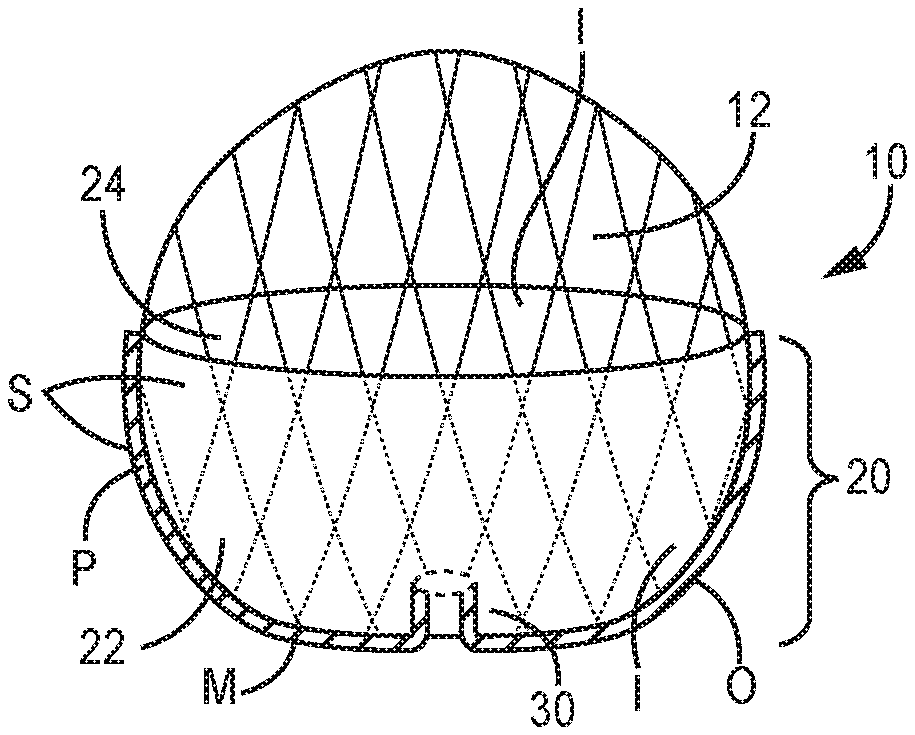
[0044] With specific reference to FIGS. 4A-11B and 16-17, exemplary embodiments of a collapsible, and expandable, anchoring structure 10 comprising an expandable stent frame 12, or other expandable material such as a wire mesh and/or a shape memory metal or polymer or the equivalent comprising an expandable and collapsible web or interconnected cells as is known in the art. Anchoring structure 10 preferably may be biased to expand to achieve the expanded state from a collapsed state, though other collapsed-to-expanded mechanisms may also be employed. Further, anchoring structure 10 may comprise a base section 20 that may be formed of the expandable stent frame 12 or equivalent and, therefore may achieve a plurality of expanded states in order to expand and contract with the natural movements of the heart chamber walls and the annulus, including the upper annular surface and/or portions of the inner throat of the annulus located between the upper annular surface or floor of the exemplary left atrium and the left ventricle.
[0045] Base section 20 comprises an outer surface 22 and an inner surface 24 and comprises a valve support 30 either integrally formed from the base section or operatively engaged or otherwise attached to base section. Valve support 30 comprises an inner surface 32 and an outer surface 34 wherein valve support 30 is adapted to substantially align with the subject annulus and allow one-way, antegrade blood flow therethrough while preventing retrograde blood flow as a result of prosthetic leaflet(s) 36 disposed on the inner surface 32 of valve support 30.
[0046] Valve support 30 may be disposed wholly or at least partially within base section 20 or may, in alternate embodiments, completely extend away from base section 20 with no part of valve support 30 within the base section 20. Thus, as shown in FIG. 4A, valve support 30 is disposed entirely within base section 20. FIG. 5 illustrates the valve support 30 extending generally entirely outside base section 20. FIG. 6 illustrates the valve support 30 partially within base section 20 and also extending away from, and outside of, base section 20. FIG. 8 illustrates a variation of the valve support 30 of FIG. 4A in that the valve support 30 is formed integrally with base section 20.
[0047] Reference is now made to exemplary boss structure 40 shown in FIG. 7, which when present may be used to align the anchoring structure 10 in the annulus and, in combination with the base section 20, assist with sealing apposition against portions of the annulus including the annular surface and inner throat of the annulus within which boss 40 extends. Boss 40 may be used in combination with any of the structures described herein including, as shown attached to or integrally formed from base section 20 and aligned with, and/or effectively extending, the flow channel defined within valve support 30. In this sense, boss 40 is similar to the extended valve support 30 of FIG. 6. In other embodiments, portions of the anchoring structure, including the valve support 30 and/or boss 40, may extend downstream in the antegrade direction away from the upper surface of the annulus into the inner throat of the annulus. In some cases, the structure may extend downward to pin the native leaflets. In other cases, the structure may extend downward into the annulus but stopping short of pinning the native leaflets.
[0048] Other variations of prosthetic valve devices are known in the art and will also benefit from variations of the present invention.
[0049] It is known to cover at least a portion, typically the lower outer portion, of an anchoring frame for a prosthetic heart valve with some fabric or tissue to help prevent PVL. Known embodiments create bunching and the like of the covering material to form a seal against PVL. These solutions however do not properly solve the fit and/or apposition problems arising from annular calcification and/or the varying and variety of the annular landscape.
[0050] Thus, with reference to the Figures, base section's outer surface 22 may be at least partially covered with a skirt S formed from, or comprising, a material M that conforms and seals with portions of the atrial wall and/or the upper annular surface. In some embodiments as illustrated, portions of the anchoring structure 10 and/or the valve support 30 may extend a distance into the annular throat, i.e., below the annular surface toward the native leaflets, wherein at least some of the anchoring structure 10 and/or valve support 30 may be covered with material M.
[0051] In some embodiment, the material M may seal with at least part of the circumferential region of the wall that encompasses the left atrial appendage (LAA) within the exemplary left atrium in order to seal the LAA.
[0052] Material M may comprise a substance or compound that is hydrophilic, wherein a skirt for base section 20 may be formed, in whole or in part, from at least material M and also be hydrophilic. In this case, the hydrophilic skirt may absorb water from the patient's blood and expand or swell to provide a tightened seal and/or apposition between the base section 20 and relevant regions of the heart chamber, thereby serving as a barrier to retrograde blood flow upon implantation, mitigating and/or preventing PVL.
[0053] The hydrophilic material M may comprise a hydrophilic gel and/or hydrophilic polymer, for example that can be selected with a swelling modulus, or more than one swelling modulus, to help ensure that the swollen material M and/or hydrophilic skirt comprising material M swells to the "right" size and further ensure that the swelling process occurs slowly and gently to allow for the device to be properly positioned in the heart chamber before substantial swelling occurs. An exemplary hydrophilic hydrogel may comprise poly(vinyl alcohol) (PVA).
[0054] The hydrogel embodiment of material M may comprise hydrophilic polymer(s) that have been chemically, physically and/or ionically crosslinked to form a matrix that swells in water. The degree of swelling of hydrogels in water is determined by a balance between the free energy of polymer/solvent mixing, ionic interactions and elastic forces and is influenced by the extent of crosslinking and the chemical nature of the polymer. The degree of swelling, in turn, determines the mesh size of the hydrogel. Hydrophilic hydrogels and/or polymers may be temperature responsive and/or pH-responsive. Some, such as chitosan and alginate are naturally occurring and offer both natural hydrophilicity and biocompatibility. Still further, swelling may be initiated by mechanical means such as agitation.
[0055] Other hydrophilic materials such as hydrophilic metals may comprise portions of the anchoring structure 10.
[0056] The hydrophilic material M may be encapsulated within easily breakable, or dissolvable or biodegradeable or bioerodable nanoparticles, wherein when the nanoparticles are broken, the hydrophilic material M is exposed to water and begin the swelling process. In this case, the prosthetic heart valve device will be positioned and implanted before any substantial swelling can occur.
[0057] Skirt S may comprise two layers of material, an inner layer I attached to the outer surface 22 of base section 20, and an outer layer 0 wherein the inner and outer layer form a pocket or a series of pockets P. The hydrophilic material M may be disposed or attached or incorporated at designed areas within the pocket or series of pockets to facilitate swelling at the interfacing regions between the expanded device and the patient's anatomy that are most vulnerable to PVL. For example, pocket or pockets may be arranged around the bottom surface of base section 20 and/or at least partially upward therefrom. Exemplary skirts S comprising pocket(s) P are shown in the Figures, with particular reference to FIGS. 12-15. As shown in FIGS. 13-15, subpockets P' may be provided within the two-layered skirt to provide discrete locating of the hydrophilic material M at regions particularly susceptible or vulnerable to insufficient apposition and/or PVL.
[0058] In embodiments as in FIGS. 5-7 and 15-17, wherein the valve support 30, or boss 40 or other structure, extends at least partially outwardly from base section 20, the skirt S may cover at least part of the outer surface 34 of the valve support 30, with hydrophilic material M integrated or otherwise comprising the skirt S including but not limited to inclusion in pocket(s) P and/or subpockets P' formed as described above.
[0059] In the embodiment comprising a boss structure, or other extension into the inner throat of the annulus, pocket(s) P and/or subpockets P' comprising material M may be formed between the boss structure and the base section 20 to swellingly close any gap between the device and the patient's anatomy. This is best shown in FIG. 15.
[0060] Alternatively, in the embodiments comprising encapsulated hydrophilic material M, the nanoparticles or capsules may be integrated, or incorporated into, or coated, attached or adhered to, the skirt in at least the PVL-vulnerable areas discussed above. Still more alternatively, the nanoparticles or capsules carrying hydrophilic material M may be affixed or adhered or coated onto or integrated into the skirt.
[0061] In certain embodiments, therefore, a pocket P formed in skirt S is not required and the skirt S may be formed of, or comprise, a single layer of material, with the hydrophilic material M affixed or adhered or coated thereon, or integrated therein, in either encapsulated or non-encapsulated forms. FIGS. 16 and 17 illustrate exemplary single layer skirts S comprising hydrophilic material M.
[0062] In alternative embodiments, portions of the anchoring structure 10 may be at least partially formed from hydrophilic material M and may be covered or overcoated by a thin film of biodegradeable, dissolvable, bioerodable and/or bioabsorbable material to delay solute interaction, and resulting swelling, with hydrophilic material M. For example, and without limitation, boss structure 40, or other extension into the inner throat of the annulus, may comprise a hydrophilic polymer that swells when contacted with a solute, e.g., water within blood. In this embodiment, a biodegradeable, bioerodable and/ bioabsorbable thin coating layer may be applied over the boss structure 40 to appropriately delay swelling until after implantation is achieved. The outer portions of the boss structure 40, i.e., those portions that are juxtaposed by and/or within the annulus and/or inner throat of the annulus, may comprise the hydrophilic material, e.g., polymer, so that only the outer portion of boss structure 40 swells in response to solute contact, leaving the dimensions of the inner boss structure 40 unaltered. Other areas of the anchoring structure 10 may also be formed from hydrophilic material M, e.g., a polymer(s), e.g., key struts or cells of the anchor 10 may comprise hydrophilic polymer that swells on solute contact.
[0063] Further, portions of anchoring structure 10 may also comprise a skirt S comprising a thin film of hydrophilic material M that may also be covered, or overcoated, temporarily during delivery and implantation by a biodegradeable, dissolvable, bioerodable and/or bioabsorbable thin film layer as described above.
[0064] Moreover, nanoparticles encapsulating hydrophilic material M as described above may be adhered or coated onto portions of anchoring structure 10 to comprise skirt S. These nanoparticles may be overcoated with a thin biodegradeable, dissolvable, bioerodable and/or bioabsorbable thin film to ensure adherence to the anchoring structure during delivery and implantation.
[0065] Each of the possible embodiments described above for implementing hydrophilic skirt comprising or incorporating hydrophilic material M may be used to cover portions of various configurations of prosthetic heart valve devices. Exemplary embodiments wherein the valve support 30 is formed from, or otherwise integrated or attached with, base section 20 are shown in FIGS. 4A, 8-10, 11A and 16-17. In this case, hydrophilic skirt S comprising hydrophilic material M as discussed above may cover the outer surface 22 of base section 20, extending to cover the bottom of base section 20 and extending further upward within base section 20 to cover the inner surface 32 of valve support 30.
[0066] In some embodiments, sealing of the left atrial appendage (LAA) may be an objective. In these cases, as shown in FIG. 15, a hydrophilic skirt S comprising hydrophilic material M may comprise a reserve pocket 100 of hydrophilic material M in the region of the LAA, wherein upon implantation, the hydrophilic material M swells to enlarge pocket 100 to cover and/or fill the LAA. The hydrophilic material M reserve may comprise a ring or gasket 102 of material M around the circumference of the skirt S so that locating the LAA is achieved no matter the rotational position of the implanted anchoring structure 10. Alternatively, the specific pocket 102 may be provided as described above that is located to the LAA for swelling sealing and/or filling of the LAA. The hydrophilic material M reserve may be formed according to the various embodiments discussed herein, including pocket(s) and/or nanoparticles and/or coating.
[0067] Generally, the improved sealing and/or apposition may therefore be improved by including hydrophilic material M at one or more locations on an anchoring structure 10. The hydrophilic material M may be associated or integrated with or incorporated with a skirt S, but this is just one embodiment. Nanoparticles, when employed, may comprise an easily breakable material and/or biodegradeable, bioerodable or dissolving material to provide the desired delay in exposing the hydrophilic material M to blood.
[0068] Still more alternatively, hydrophilic material-containing nanoparticles may be injected or otherwise delivered to the relevant regions of the implanted device, either after expansion and implantation is fully achieved, or just prior to full expansion and implantation. Further, hydrophilic material M may be injected or otherwise delivered without encapsulation to the relevant regions of the implanted device, either after expansion and implantation is fully achieved or just prior to full expansion and implantation. The injection or delivery of the hydrophilic material M, whether or not encapsulated, may be achieved by providing a reservoir of hydrophilic material M (encapsulated or not) that is, by known techniques, delivered through a delivery device comprising a lumen in fluid communication with the reservoir. The distal tip of delivery device may be manipulated by the operator, by e.g., use of a push/pull wire(s) or the like, to enable delivery at the discreet regions of interest at or around the device and related anatomy. The delivery device described here may be a modification of the delivery catheter and related mechanisms for delivery of the prosthetic device to the subject heart chamber.
[0069] Moreover, the device may comprise at least one ridge, flap or ring operatively attached to the skirt and comprising hydrophilic material M as discussed herein, wherein the at least one ridge, flap or ring may in some cases be adapted to seal against or within the left atrial appendage and/or against the annulus of the subject heart chamber.
[0070] The description of the invention and its applications as set forth herein is illustrative and is not intended to limit the scope of the invention. Features of various embodiments may be combined with other embodiments within the contemplation of this invention. Variations and modifications of the embodiments disclosed herein are possible, and practical alternatives to and equivalents of the various elements of the embodiments would be understood to those of ordinary skill in the art upon study of this patent document. These and other variations and modifications of the embodiments disclosed herein may be made without departing from the scope and spirit of the invention.
* * * * *
D00000
D00001
D00002
D00003
D00004
D00005
D00006
D00007
D00008
XML
uspto.report is an independent third-party trademark research tool that is not affiliated, endorsed, or sponsored by the United States Patent and Trademark Office (USPTO) or any other governmental organization. The information provided by uspto.report is based on publicly available data at the time of writing and is intended for informational purposes only.
While we strive to provide accurate and up-to-date information, we do not guarantee the accuracy, completeness, reliability, or suitability of the information displayed on this site. The use of this site is at your own risk. Any reliance you place on such information is therefore strictly at your own risk.
All official trademark data, including owner information, should be verified by visiting the official USPTO website at www.uspto.gov. This site is not intended to replace professional legal advice and should not be used as a substitute for consulting with a legal professional who is knowledgeable about trademark law.