Surgical Stapling Apparatus With Firing Lockout Mechanism
Cappola; Kenneth M.
U.S. patent application number 16/866936 was filed with the patent office on 2020-08-20 for surgical stapling apparatus with firing lockout mechanism. The applicant listed for this patent is Covidien LP. Invention is credited to Kenneth M. Cappola.
| Application Number | 20200261079 16/866936 |
| Document ID | 20200261079 / US20200261079 |
| Family ID | 1000004799139 |
| Filed Date | 2020-08-20 |
| Patent Application | download [pdf] |


View All Diagrams
| United States Patent Application | 20200261079 |
| Kind Code | A1 |
| Cappola; Kenneth M. | August 20, 2020 |
SURGICAL STAPLING APPARATUS WITH FIRING LOCKOUT MECHANISM
Abstract
A surgical stapling apparatus is provided which includes a first jaw supporting an anvil assembly and a second jaw supporting a cartridge assembly. The cartridge assembly supports a firing lockout assembly which includes a latch member having a blocking member. The latch member is movable between a first position and a second position. In the first position, the blocking member of the latch member is aligned with the stop surface of the drive member to prevent advancement of the drive member within the tool assembly and in the second position, the blocking member is misaligned with the stop surface of the drive member to permit advancement of the drive member within the tool assembly. A biasing member is positioned to urge the latch member towards the first position. In the retracted position of the drive member, the latch member is in the first position.
| Inventors: | Cappola; Kenneth M.; (Monroe, CT) | ||||||||||
| Applicant: |
|
||||||||||
|---|---|---|---|---|---|---|---|---|---|---|---|
| Family ID: | 1000004799139 | ||||||||||
| Appl. No.: | 16/866936 | ||||||||||
| Filed: | May 5, 2020 |
Related U.S. Patent Documents
| Application Number | Filing Date | Patent Number | ||
|---|---|---|---|---|
| 15690620 | Aug 30, 2017 | 10675023 | ||
| 16866936 | ||||
| 14230516 | Mar 31, 2014 | 9757126 | ||
| 15690620 | ||||
| Current U.S. Class: | 1/1 |
| Current CPC Class: | A61B 2090/0814 20160201; A61B 2017/00473 20130101; A61B 2017/07271 20130101; A61B 17/072 20130101; A61B 17/07207 20130101; A61B 2017/07257 20130101 |
| International Class: | A61B 17/072 20060101 A61B017/072 |
Claims
1. (canceled)
2. A lockout assembly configured to prevent a tool assembly from firing, the lockout assembly comprising: a mounting member; a post disposed parallel to a longitudinal axis of the tool assembly; a biasing member configured to urge the post distally in a direction parallel to the longitudinal axis, the biasing member positioned between the post and the mounting member; and a latch member pivotally supported by the mounting member, the latch member having an abutment surface and a projection, the post engaged with the latch member to urge the abutment surface of the latch member towards a locked position in which the projection is positioned to engage an actuation sled of the tool assembly to prevent advancement of the actuation sled.
3. The lockout assembly of claim 2, wherein the mounting member defines a pair of hooks disposed on opposite sides of the longitudinal axis.
4. The lockout assembly of claim 3, wherein the latch member includes laterally extending wings, each of the laterally extending wings received by one of the pair of hooks to pivotally support the latch member relative to the mounting member.
5. The lockout assembly of claim 2, wherein the latch member has a first leg and a second leg interconnected by a proximal base member, the first and second legs parallel to and spaced apart from one another on opposite sides of the longitudinal axis.
6. The lockout assembly of claim 5, wherein the base member is configured to engage the mounting member to prevent the latch member from pivoting beyond the locked position.
7. The lockout assembly of claim 2, wherein the post is engaged with the latch member to urge the abutment surface of the latch member distally such that the latch member is pivoted towards the locked position.
8. The lockout assembly of claim 7, wherein the post is configured to pivot the latch member towards the locked position such that the projection of the latch member is pivoted transverse to the longitudinal axis to engage the actuation sled to prevent advancement of the actuation sled.
9. A lockout assembly comprising: a mounting member; a biasing member; and a latch member pivotally supported by the mounting member and including a blocking member, a pivot member, and a projection, the latch member pivotable about a pivot axis defined by the pivot member between a locked position in which the blocking member is in a blocking position and an unlocked position, the projection positioned distally of the pivot member and the blocking member positioned proximally of the pivot member, the biasing member urging the latch member towards the locked position, wherein application of a force to the projection in a first direction pivots the blocking member in a second opposite direction to move the latch member from the locked position to the unlocked position.
10. The lockout assembly of claim 9, further including a post engaged with the latch member and defining an axis that is orthogonal to the pivot axis, wherein the biasing member urges the post distally to urge the latch member towards the locked position.
11. The lockout assembly of claim 10, wherein the biasing member is positioned between the post and the mounting member.
12. The lockout assembly of claim 9, wherein the mounting member defines hooks, the hooks disposed on opposite sides of the latch member along the pivot axis.
13. The lockout assembly of claim 12, wherein the latch member includes a laterally extending wings, each of the laterally extending wings received by one of the hooks of the mounting member to pivotally support the latch member on the mounting member.
14. The lockout assembly of claim 9, wherein the latch member includes a first leg and a second leg, the first and second legs of the latch member having proximal portions that are interconnected by a base member, the first and second legs extending along axes that are parallel to and spaced apart from one another.
15. The lockout assembly of claim 14, wherein the base member is configured to engage the mounting member to prevent the latch member from pivoting beyond the locked position.
16. The lockout assembly of claim 14, wherein the projection includes two projections and each of the first and second legs includes one of the two projections.
17. The lockout assembly of claim 9, wherein the latch member includes an abutment surface and the post is engaged with the abutment surface.
18. A tool assembly comprising: an anvil assembly; a cartridge assembly coupled to the anvil assembly, the anvil assembly and cartridge assembly movable between an unapproximated position and an approximated position; a drive member movable from a retracted position to an advanced position to move the anvil assembly and the cartridge assembly from the unapproximated position to the approximated position, the drive member having a stop surface; and a lockout assembly according to claim 9.
19. The tool assembly of claim 18, wherein the cartridge assembly includes an actuation sled positioned to be engaged by the drive member as the drive member is moved from the retracted position towards the advanced position to move the actuation sled from a retracted position to an advanced position, wherein it its retracted position, the actuation sled engages the projection of the latch member to move the latch member from its locked position to its unlocked position.
20. The tool assembly of claim 19, wherein the drive member abuts the actuation sled as the drive member moves from its retracted position towards its advanced position to move the actuation sled from its retracted position towards its advanced position.
Description
CROSS-REFERENCE TO RELATED APPLICATIONS
[0001] The present application is a Continuation of U.S. application Ser. No. 15/690,620, filed Aug. 30, 2017 which is a Continuation of U.S. application Ser. No. 14/230,516, filed on Mar. 31, 2014, now U.S. Pat. No. 9,757,126. Each of these disclosures is incorporated by reference herein in its entirety.
1. TECHNICAL FIELD
[0002] The present disclosure relates to surgical stapling apparatus. More particularly, the present disclosure relates to surgical stapling apparatus having a firing lockout mechanism.
2. BACKGROUND
[0003] Surgical stapling apparatus for stapling tissue are well known in the art and typically include a handle assembly, a body portion extending distally from the handle assembly, and a tool assembly supported on the distal end of the body portion. The tool assembly includes first and second jaws which are movable in relation to each other between unapproximated and approximated positions. The first jaw supports an anvil assembly and the second jaw supports a cartridge assembly which houses a plurality of staples. The cartridge can also include a knife for severing tissue. In known apparatus, a fired or spent cartridge can be replaced with an unfired or fresh cartridge to facilitate reuse of the surgical stapling apparatus.
[0004] In order to prevent refiring of the surgical stapling apparatus with a spent cartridge, or to prevent firing of a surgical stapling apparatus which does not include a cartridge, it is known to provide a lockout mechanism which prevents advancement of a drive member of the stapling apparatus. Although known lockout mechanisms are effective to prevent firing of a surgical stapling apparatus which includes a spent cartridge or does not include a cartridge, an improved, reliable lockout mechanism is desired.
SUMMARY
[0005] A surgical stapling apparatus provided in accordance with the present disclosure includes a body portion defining a longitudinal axis having a proximal end and a distal end, and a tool assembly supported on the distal end of the body portion. The tool assembly includes an anvil assembly and a cartridge assembly and is movable from an unapproximated position to an approximated position. A drive member is movably supported within the tool assembly from a retracted position to an advanced position to move the tool assembly from the unapproximated position to the approximated position. The drive member has a stop surface. A firing lockout assembly includes a latch member having a blocking member and a biasing member. The latch member is pivotally supported within the tool assembly and movable from a first position to a second position, wherein in the first position the blocking member of the latch member is aligned with the stop surface of the drive member to prevent advancement of the drive member within the tool assembly and in the second position the blocking member is misaligned with the stop surface of the drive member to permit advancement of the drive member within the tool assembly. The biasing member is positioned to urge the latch member towards the first position such that in the retracted position of the drive member, the latch member is in the first position.
[0006] In embodiments, the cartridge assembly includes an actuation sled positioned within the tool assembly to be engaged by the drive member as the drive member is moved from the retracted position towards the advanced position. The drive member effects movement of the actuation sled from a retracted position to an advanced position upon movement of the drive member from the retracted position to the advanced position.
[0007] In embodiments, the actuation sled is configured to engage the latch member to move the latch member from the first position to the second position when the actuation sled is advanced distally within the cartridge assembly by the drive member.
[0008] In embodiments, the latch member includes a u-shaped body including a base member which supports the blocking member and a pair of spaced legs extending distally from the base member. Each of the spaced legs supports a centrally located pivot member and has a distal projection.
[0009] In embodiments, the actuation sled includes at least one proximal finger which is positioned to engage one of the distal projections of the pair of spaced legs of the latch member as the actuation sled is moved distally within the cartridge assembly to effect movement of the latch member from the first position to the second position.
[0010] In embodiments, the at least one proximal finger includes two proximal fingers, each of which are positioned to engage a respective one of the distal projections of the pair of spaced legs of the latch member to effect movement of the latch member from the first position to the second position.
[0011] In embodiments, the surgical stapling apparatus includes a mounting assembly including a mounting portion, wherein the mounting portion defines a pair of hooked arms. Each of the pivot members of the latch member is supported on a respective one of the pair of hooked arms.
[0012] The drive member includes a body and a working end. The working end includes an upper flange and a lower flange interconnected by a vertical strut and is positioned to engage the actuation sled to move the actuation sled distally within the cartridge assembly.
[0013] In embodiments, the mounting assembly defines a shoulder positioned to engage the blocking member to retain the latch member in the first position.
[0014] In embodiments, the anvil assembly defines a first cam surface and the cartridge assembly defines a second cam surface and the drive member is movable from the retracted position to an intermediate position. In the intermediate position, the upper and lower flanges of the working end of the drive member engage the first and second cam surfaces to move the tool assembly to the approximated position.
[0015] In embodiments, the proximal finger of the actuation sled is engaged with one of the distal projections of the latch member to retain the latch member in the second position the intermediate position of the drive member.
[0016] In embodiments, the blocking member of the latch member is positioned to engage a bottom surface of the body of the drive member as the drive member is moved from the intermediate position towards the advanced position to retain the latch member in the second position.
[0017] In embodiments, the actuation sled is in abutting relationship with the working end of the drive member such that upon movement of the drive member from the advanced position back to the retracted position, the actuation sled remains in a distal end of the cartridge assembly.
BRIEF DESCRIPTION OF THE DRAWINGS
[0018] Various embodiments of the present disclosure are described herein with reference to the drawings, wherein:
[0019] FIG. 1 is a side, perspective view of an embodiment of the presently disclosed surgical stapling apparatus including a tool assembly in an unapproximated position;
[0020] FIG. 1A is a side, perspective view of a disposable reload of the surgical stapling apparatus shown in FIG. 1;
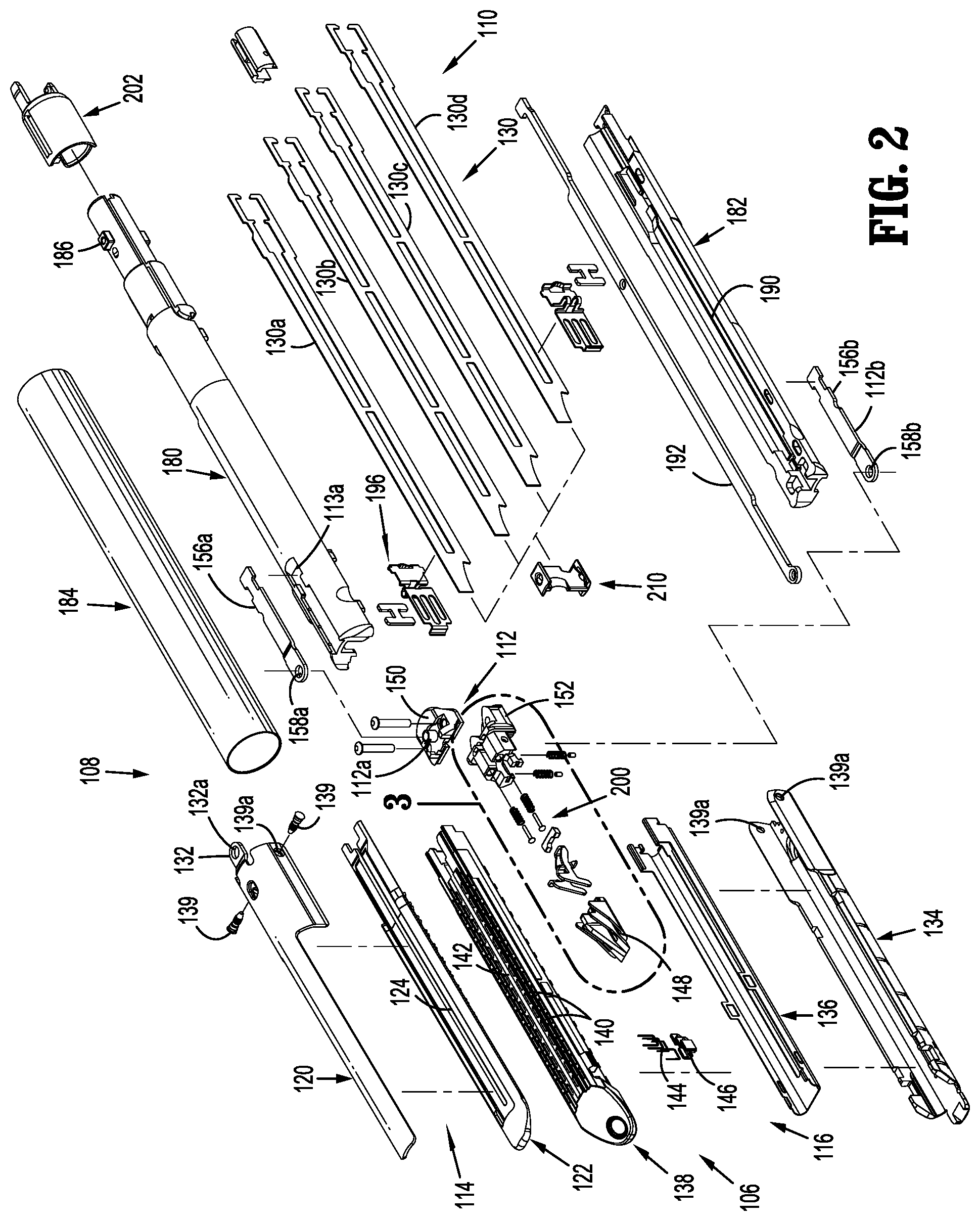
[0021] FIG. 2 is a side, perspective view of the replaceable reload shown in FIG. 1A with parts separated;
[0022] FIG. 3 is an enlarged, side perspective view of the indicated area of detail shown in FIG. 2;
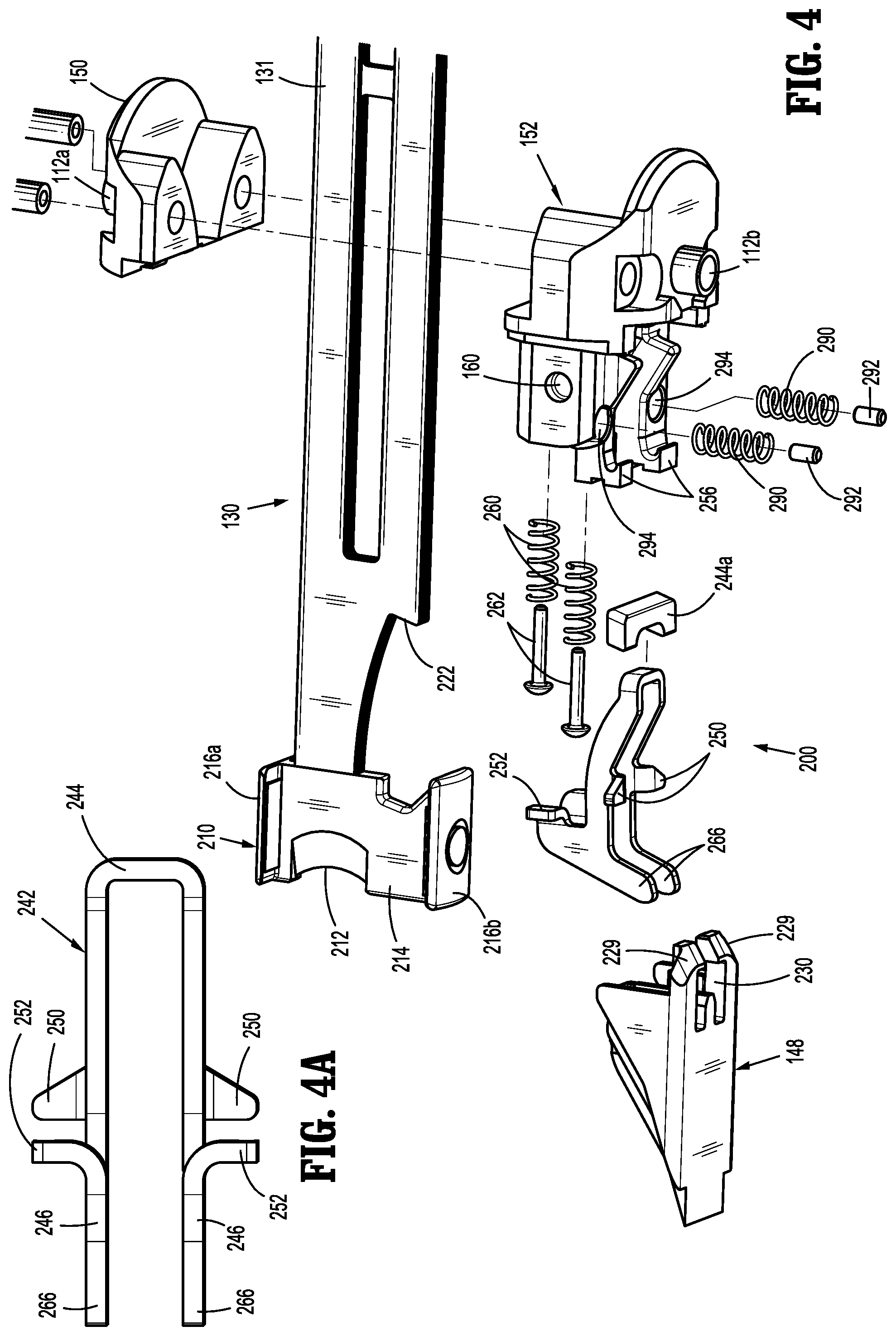
[0023] FIG. 4 is a side perspective view with parts separated of a mounting assembly, lockout mechanism and wedge member positioned adjacent a distal end of a drive member of the surgical stapling apparatus;
[0024] FIG. 4A is a top plan view of a latch member.
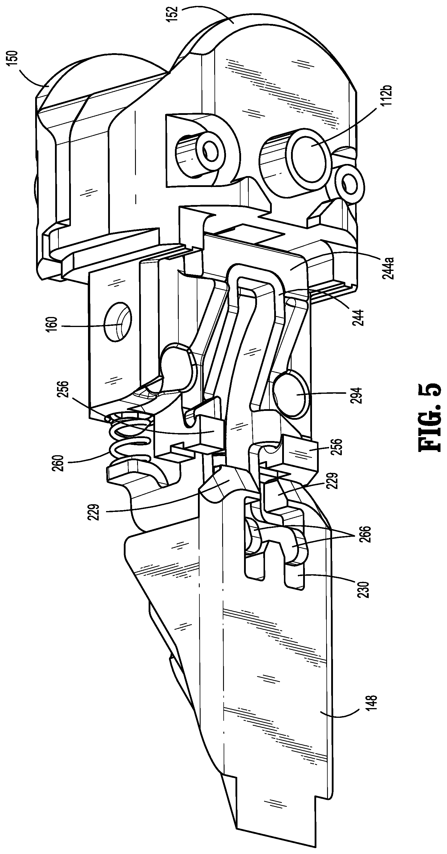
[0025] FIG. 5 is a perspective view from the bottom of the wedge member, lockout mechanism and mounting assembly of the disposable reload shown in FIG. 1A in an assembled state;
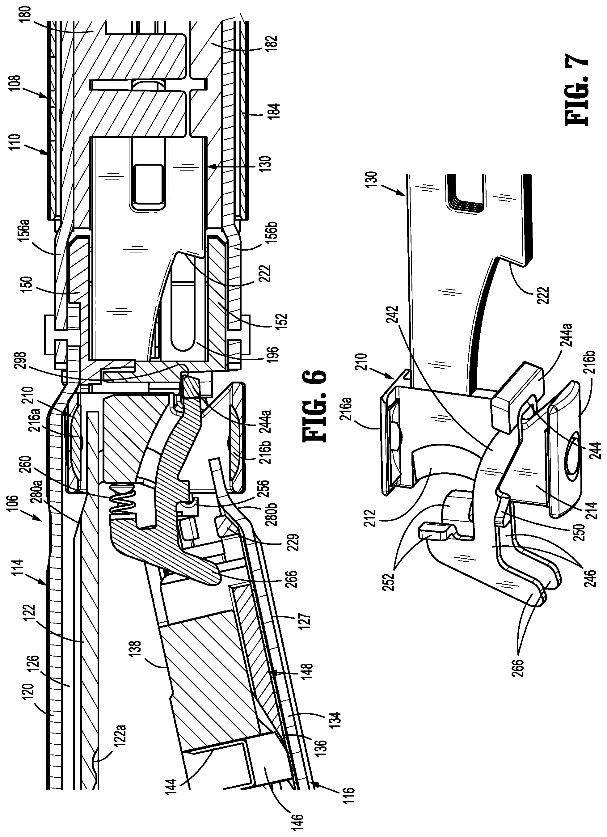
[0026] FIG. 6 is a side, cross-sectional view of the proximal end of the tool assembly, the mounting assembly, and distal end of the body portion of the surgical stapling apparatus shown in FIG. 1 with the tool assembly in the open position prior to firing of the surgical stapling apparatus;
[0027] FIG. 7 is a side, perspective view of a latch member of the lockout mechanism supported on the mounting assembly adjacent a working end of the drive member;
[0028] FIG. 7A is a side, cross-sectional view of the proximal end of the tool assembly, the mounting assembly, and the distal end of the proximal body portion of the reload of the surgical stapling apparatus shown in FIG. 1 with the working end of the drive member advanced to engage the wedge member;
[0029] FIG. 7B is a side, perspective view of the latch member of the lockout mechanism supported on the mounting assembly adjacent the working member of the drive member with the working member moved into engagement with the wedge member in the position shown in the FIG. 7A;
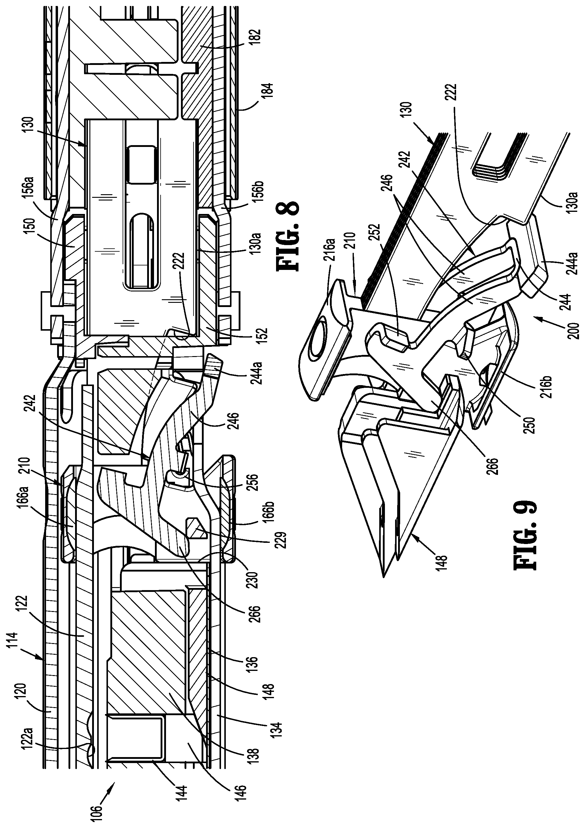
[0030] FIG. 8 is a side, cross-sectional view of the proximal end of the tool assembly, the mounting assembly, and the distal end of the proximal body portion of the reload of the surgical stapling apparatus shown in FIG. 1 with the working member advanced to a position to advance the wedge member into engagement with the latch member to begin to rotate the latch member in a clockwise direction to an unlocked position;
[0031] FIG. 9 is a side perspective view of the latch member of the lockout mechanism supported on the working end of the drive member, with parts removed, in the position shown in FIG. 8;
[0032] FIG. 10 is a side, cross-sectional view of the proximal end of the tool assembly, the mounting assembly, and the distal end of the proximal body portion of the reload of the surgical stapling apparatus shown in FIG. 1 with the working member advanced to a position to advance the wedge member to support the latch member in the unlocked position;
[0033] FIG. 11 is a side, perspective view of the latch member of the lockout mechanism supported on the mounting assembly adjacent the working end of the drive member, with parts removed, in the position shown in FIG. 10;
[0034] FIG. 11A is a side, cross-sectional view of the proximal end of the tool assembly, the mounting assembly, and the distal end of the proximal body portion of the reload of the surgical stapling apparatus shown in FIG. 1 with the working member advanced to a position to advance the wedge member beyond the latch member such that the latch member is supported in the unlocked position by the drive member;
[0035] FIG. 11B is a side, perspective view of the latch member of the lockout mechanism supported on the mounting assembly adjacent the working end of the drive member, with parts removed, in the position shown in FIG. 11A;
[0036] FIG. 12 is a side, cross-sectional view of the proximal end of the tool assembly, the mounting assembly, and the distal end of the proximal body portion of the reload of the surgical stapling apparatus shown in FIG. 1 with the working end of the drive member retracted and the latch member moving to the locked position; and
[0037] FIG. 13 is a side, perspective view of the latch member of the lockout mechanism supported on the mounting assembly adjacent the working end of the drive member in the locked position shown in FIG. 12.
DETAILED DESCRIPTION OF EMBODIMENTS
[0038] Embodiments of the presently disclosed surgical stapling apparatus including a firing lockout mechanism will now be described in detail with reference to the drawings wherein like reference numerals designate identical or corresponding elements in each of the several views. In this description, the term "proximal" is generally used to refer to the portion of the apparatus that is closer to a clinician, while the term "distal" is generally used to refer to the portion of the apparatus that is farther from the clinician.
[0039] FIGS. 1 and 1A illustrate an embodiment of the presently disclosed surgical stapling apparatus shown generally as 100. The surgical stapling apparatus 100 includes a handle assembly 102, a body portion 104, and a tool assembly 106. The handle assembly 102 includes a stationary handle 102a, a movable handle 102b, a retraction member 107a and an articulation member 107b. In embodiments, the tool assembly 106 forms part of a replaceable reload 108 which also includes a proximal reload body portion 110 which supports the tool assembly 106. The reload 108 will be discussed in further detail below. Alternatively, the tool assembly 106 can be supported directly on the distal end of the body portion 104.
[0040] Referring to FIGS. 1A and 2, the replaceable reload 108 includes the tool assembly 106, the proximal body portion 110, an intermediate mounting assembly 112, a drive member 130 and firing lockout assembly 200 which will be described in further detail below. The mounting assembly 112 is secured to the tool assembly 106 and is pivotally coupled to the proximal body portion 110 of the reload 108 to pivotally secure the tool assembly 106 to the proximal body portion 110. The reload 108 is substantially as described in US Publication No. 2013/0098965 ("the '965 publication") except that the firing lockout mechanism has been changed. US Publication No. 2013/0098965 is hereby incorporated by reference herein in its entirety. Accordingly, the components of the reload 108 which are common to that which is disclosed in the '965 publication will be briefly described herein and the new firing lockout mechanism 200 and its method of operation will be described in detail herein.
[0041] The tool assembly 106 includes an anvil assembly 114 and a cartridge assembly 116 which are movable in relation to each other between unapproximated and approximated positions. The anvil assembly 114 includes an anvil body 120 and an anvil plate 122 which is secured to the underside of the anvil body 120 to define a channel 126 (FIG. 6). The anvil plate 122 defines plurality of staple receiving depressions 122a (FIG. 6) and a longitudinal slot 124 which is dimensioned to slidably receive a portion of the working end 210 of a drive member 130 of the disposable reload 108 as will be discussed in further detail below. A proximal end of the anvil body 120 includes a bracket 132 defining a hole 132a for receiving a cylindrical pivot member 112a of the mounting assembly 112.
[0042] The cartridge assembly 116 includes a support plate 136, cartridge body 138, a plurality of staples, and a staple firing assembly that includes a sled 148 and is further discussed below. The cartridge assembly 116 is receivable in a channel 134 or channel assembly. The cartridge body 138 and the support plate 136 are attached to the channel 134 by a snap-fit connection as described in the '965 publication which has been incorporated herein by reference. Other forms of connection are contemplated and can be used in place of a snap-fit, or in addition thereto. The channel 134 or channel assembly is pivotally secured to the anvil body 120 by pivot members 139 which extend through openings 139a formed in the anvil body 120 and the channel 134. The cartridge body 138 defines a plurality of laterally spaced staple retention slots 140 which are positioned in alignment with the staple forming depressions 122 in a tissue contacting surface 142 of the cartridge body 138. Each slot 140 is configured to receive a fastener or staple 144 and a pusher 146. The actuation sled 148 is positioned within the cartridge body 138 to pass longitudinally through the cartridge body 138 into engagement with the pushers 146 to sequentially eject the staples 144 from the cartridge body 138. For a more detailed discussion of the cartridge assembly 116 including the support plate 136, see the '965 publication which has been incorporated herein by reference
[0043] Referring also to FIGS. 3-5, the mounting assembly 112 includes an upper mounting portion 150 and a lower mounting portion 152 which are secured together by posts 153 or rivets. Each of the mounting portions 150 and 152 includes a pivot member 112a and 112b, respectively. As discussed above, the pivot member 112a is received within the hole 132a of the bracket 132 (FIG. 2) of the anvil body 120 to secure the upper mounting portion 150 to the anvil body 120. A first coupling member 156a (FIG. 2) has a first end which defines an opening 158a which also receives the pivot member 112a and a second end which is received within a recess 113a defined in the proximal body portion 110 of the replaceable reload 108. The pivot member 112b is supported on the lower mounting portion 152 and is received in an opening 158b of a second coupling member 156b. The second coupling member 156b is received within a recess similar to recess 113a defined in the proximal body portion 152 to pivotally secure the lower mounting portion 152 to the proximal body portion 110 of the reload 108. The pivot members 139 extend through the openings 139a formed in the anvil body 120 and the channel 134 and are received in openings 160 (FIG. 3) formed in lower mounting portion 152 to secure the lower mounting portion 152 to the channel 134.
[0044] Referring again to FIG. 2, the proximal body portion 110 of the reload 108 includes an upper housing half 180 and a lower housing half 182 which are contained within an outer sleeve 184. When the outer sleeve 184 is positioned about the upper and lower housing halves 180 and 182, the first and second coupling members 156a and 156b are retained within the recesses 113a to prevent separation of the tool assembly 106 and the proximal body portion 110 of the reload 108. The proximal end of the upper housing half 182 and/or lower housing half include engagement nubs 186 for releasably engaging the distal end of the body portion 104 of the stapling apparatus 100 in a bayonet-type coupling arrangement. The housing halves 180 and 182 define a channel 190 for slidably receiving the drive member 130. An articulation link 192 is dimensioned to be slidably positioned between the upper and the lower housing halves 180 and 182 and is adapted to engage an articulation mechanism (not shown) of the surgical stapling apparatus 100. A pair of blow out plate assemblies 196 are positioned adjacent the distal end of the housing halves 180 and 182 to prevent outward buckling and bulging of the drive member 130 during articulation and firing of the tool assembly 106 stapling apparatus 100. A more detailed discussion of the components of the proximal body portion 110 is provided in U.S. Pat. No. 7,143,924 to Scirica et al. ("the '924 patent") which is hereby incorporated by reference herein in its entirety.
[0045] Referring also to FIGS. 4-7, the drive member 130 includes a body and a working end 210 having a knife 212. The working end 210 includes an upper flange 216a a lower flange 216b and a vertical strut 214 interconnecting the upper flange 216a and the lower flange 216b. The knife 212 is supported on or formed into the vertical strut 214 of the working end 210. The upper flange 216a is positioned to be slidably received within the channel 126 (FIG. 6) of the anvil assembly 114 and the lower flange 126b is positioned to be slidably positioned along an outer surface 127 of the channel 134. In use, distal movement of the drive member 130 initially advances the upper flange 216a into a cam surface 280a formed on the anvil plate 122 and advances the lower flange 216b into engagement with a cam surface 280b formed on the channel 134 to pivot the cartridge assembly 116 towards the anvil assembly 114 to a closed or approximated position. Continued advancement of the drive member 130 progressively maintains a minimum tissue gap adjacent the working end 210 as the working end 210 moves through the tool assembly 106.
[0046] In certain embodiments, the body of the drive member 130 is formed from a plurality of stacked sheets 130a-d of material, e.g., stainless steel. A locking member 202 is supported about the proximal end of the reload 108 to prevent axial movement of the drive member until the reload 108 is attached to the stapling apparatus 100. A more detailed discussion of the above-identified components of the disposable reload 108 is described in the '924 patent which has been incorporated herein by reference in its entirety.
[0047] The distal end of the body of the drive member 130 supports the working end 210 and defines a stop surface 222. The sled 148 is disposed within the cartridge assembly 116 at a position distal of the working end 210. When the working end 210 is in its proximal-most position and the tool assembly 106 is in the open or unapproximated position (FIG. 6), the sled and the working end are in their initial position. The sled 148 includes a plurality of cam surfaces 228 (FIG. 3) which are positioned to engage the pushers 146 which are positioned within the cartridge assembly 116 to eject the staples 144 from the cartridge body 136 when the sled 148 is advanced through the tool assembly 106. The proximal end of the sled 148 includes one or more fingers 229 which define an opening 230 or slot (FIG. 4) which will be discussed in further detail below.
[0048] The firing lockout assembly 200 includes a latch member 242 which is pivotally supported on a distal end of the lower mounting portion 152. The latch member 242 includes a U-shaped body (FIG. 4A) having a proximal base member 244 and two spaced distally extending legs 246. The base member 244 can be provided with a blocking member 244a which defines a blocking surface and can be welded or secured to the base member 244 to provide additional support to the base member 244. Alternatively, the proximal end of the base member 244 can define the blocking surface. The latch member 242 is pivotal from a first position to a second position. In the first position, the blocking member 244a of the latch member 242 is aligned with the stop surface 222 of the drive member 130 to prevent advancement of the drive member 130 within the tool assembly 106 and in the second position, the blocking member 244a is misaligned with the stop surface 222 of the drive member 130 to permit advancement of the drive member 130 within the tool assembly 106.
[0049] Referring to FIGS. 3-6, each leg 246 of the latch member 242 has a centrally located pivot member 250 and an abutment surface 252. The pivot members 250 are supported on hooked arms 256 of the lower mounting portion 152 of the mounting assembly 112 to pivotally support the latch member 242 on the lower mounting portion 152. A biasing member or members is provided to urge the latch member 242 towards the first position. In certain embodiments, the biasing member includes a pair of springs 260 which are supported about respective posts 262 affixed to a distal face of the lower mounting portion 152. Each spring 260 is positioned to engage a respective abutment surface 252 of the latch member 242 to bias the latch member 242 in a counter-clockwise direction as viewed in FIG. 6. A distal end of each leg 246 includes a downwardly extending projection 266 which is positioned to extend through the opening 230 defined in the sled 148 when the sled 148 is in a retracted position, the latch member 242 is in the first position and the anvil assembly 114 and the cartridge assembly 116 are in the approximated position (FIG. 7A).
[0050] Referring to FIGS. 3 and 4, a spring 290 is disposed about each cylinder 292 within the channel 134. Each of the cylinders 292 is affixed to an inner surface of the channel 134 to provide alignment and stability to the springs 290. Each of the springs 290 is positioned between the inner surface of the channel 134 and a respective blind bore 294 (FIG. 4) defined in a bottom surface of the lower mounting portion 152 to urge the tool assembly 106 to the unapproximated position. Other biasing members or features can be used in place of the springs.
[0051] Referring to FIGS. 6 and 7, when the drive member 130 is in the fully retracted position and the tool assembly 106 is in the unapproximated or open position, the upper and lower flanges 216a and 216b of the working end 210 of the drive member 130 are spaced proximally of the sled 148 and proximally of cam surfaces 280a and 280b formed on the anvil plate 122 and the channel 134, respectively. In the unapproximated position of the tool assembly 106, the latch member 242 is urged towards a counter-clockwise position by springs 260. The lower mounting portion 152 includes a surface 298 which is positioned to engage the base member 244 or blocking member 244a. Engagement between the blocking member 244a and the surface 298 of the lower mounting portion 152 prevents further counter-clockwise rotation of the latch member 242 to retain the latch member 242 in the first position.
[0052] Referring to FIGS. 7A-7B, when the drive member 130 is advanced distally by actuating the movable handle 102b (FIG. 1), the upper and lower flanges 216a and 216b of the working end 210 engage the cam surfaces 280a and 280b and pivot the cartridge assembly 116 towards the anvil assembly 114 to move the tool assembly 106 to the approximated position. When the tool assembly 106 is in the approximated position, the latch member 242 remains in the first position such that the downwardly extending projections 266 of legs 246 of latch member 242 extend through the opening 230 of sled 148 and engage the inner surface of the channel 134. In the first position, the blocking member 244a is aligned with but spaced from the stop surface 222 on the distal end of the body of the drive member 130. The working end 210 of the drive member 130 is also positioned proximally of the major portion of the sled 148.
[0053] Referring to FIGS. 8 and 9, when the movable handle 102a is actuated to fire the stapling apparatus 100 and eject staples 144 from cartridge body 136 of cartridge assembly 116, the drive member 130 is advanced to move the working end 210 of the drive member 130 through the tool assembly 106 into engagement with the sled 148 to advance the sled 148 distally through the tool assembly 106. As the sled 148 moves distally through the tool assembly 106, the proximal fingers 229 of the sled 148, which partially define the opening 230, engage the downwardly extending projections 266 of the latch member 242 to pivot the latch member 242 about the pivot members 250 of the latch member 242 in a clockwise direction, as shown in FIG. 9, against the bias of springs 260. As the latch member 242 pivots in the clockwise direction towards the second position, the blocking member 244a is pivoted downwardly out from alignment with the stop surface 222.
[0054] As viewed in FIGS. 10-11B, continued advancement of the drive member 130 effects continued advancement of the sled 148. As the sled 148 is advanced, the fingers 229 of the actuation sled 148 retain the latch member 242 in the second position to allow the base 130a of the drive member 130 to pass over the blocking member 244a. The base 130a of the drive member 130 retains the latch member 242 in the second position with the blocking member 244a positioned beneath the stop surface 222 of the drive member 130.
[0055] Referring to FIGS. 12 and 13, when the stapling apparatus 100 has been fired and the drive member 130 is returned to the retracted position, the actuation sled 148 which was in abutting relationship with the drive member 130, remains in the distal end of the cartridge body 138. The latch member 242 is returned to the first position by the springs 260 after the base 130a of the drive member 130 moves to a position proximally of the latch member 242. In the retracted position of the drive member 130, the latch member 242 is returned to the first position by the biasing springs 260 such that the blocking member 244a is positioned in alignment with the stop surface 222 of the drive member 130 to prevent readvancement of the drive member 130. Also, the working end has an angled cam surface facing in a proximal direction, and located on the vertical strut, that can urge the latch toward the first position.
[0056] As illustrated in FIG. 12, with the sled 148 in its advanced position, the fingers 229 of the sled 148 are positioned distally of the downwardly extending projections 266 of the latch member 242. Thus, readvancement of the drive member 130 does not effect pivoting of the latch member 242 from the first position to the second position, and readvancement of the drive member 130 is prevented.
[0057] In order to reuse stapling apparatus 100, the drive member 130 must be fully retracted and the cartridge assembly must be replaced. More specifically, the cartridge assembly is removed from the channel 134 and a new cartridge assembly is positioned within the channel 134. The new cartridge assembly has a sled 148 positioned such that advancement of the sled 148 causes fingers 229 again to engage and pivot the latch member 242 from the first position to the second position, and allowing the drive member to be advanced.
[0058] Persons skilled in the art will understand that the devices and methods specifically described herein and illustrated in the accompanying drawings are non-limiting exemplary embodiments. It is envisioned that the elements and features illustrated or described in connection with one exemplary embodiment may be combined with the elements and features of another without departing from the scope of the present disclosure. As well, one skilled in the art will appreciate further features and advantages of the disclosure based on the above-described embodiments. Accordingly, the disclosure is not to be limited by what has been particularly shown and described, except as indicated by the appended claims.
* * * * *
D00000
D00001
D00002
D00003
D00004
D00005
D00006
D00007
D00008
D00009
D00010
D00011
D00012

XML
uspto.report is an independent third-party trademark research tool that is not affiliated, endorsed, or sponsored by the United States Patent and Trademark Office (USPTO) or any other governmental organization. The information provided by uspto.report is based on publicly available data at the time of writing and is intended for informational purposes only.
While we strive to provide accurate and up-to-date information, we do not guarantee the accuracy, completeness, reliability, or suitability of the information displayed on this site. The use of this site is at your own risk. Any reliance you place on such information is therefore strictly at your own risk.
All official trademark data, including owner information, should be verified by visiting the official USPTO website at www.uspto.gov. This site is not intended to replace professional legal advice and should not be used as a substitute for consulting with a legal professional who is knowledgeable about trademark law.