Extendable Jet Assembly and Liquid Circulation System
Arsin; Carl ; et al.
U.S. patent application number 16/782115 was filed with the patent office on 2020-08-20 for extendable jet assembly and liquid circulation system. The applicant listed for this patent is Sundance Spas, Inc.. Invention is credited to Carl Arsin, Mark Knight.
| Application Number | 20200260916 16/782115 |
| Document ID | 20200260916 / US20200260916 |
| Family ID | 1000004672895 |
| Filed Date | 2020-08-20 |
| Patent Application | download [pdf] |


View All Diagrams
| United States Patent Application | 20200260916 |
| Kind Code | A1 |
| Arsin; Carl ; et al. | August 20, 2020 |
Extendable Jet Assembly and Liquid Circulation System
Abstract
An extendable jet assembly for a liquid-filled container includes a housing configured to be positioned in an opening in a wall of the container. The housing includes a proximal end configured to be connected to a liquid conduit, a distal end connected to the opening in the wall, and a sidewall extending therebetween. The jet assembly also includes an extendable jet at least partially mounted in the housing defining a liquid channel extending between a proximal end and a distal end thereof. The jet includes a valve at least partially disposed in the liquid channel of the jet. When the valve is open, the jet is configured to transition from a retracted position to an extended position. When the valve is closed the jet is configured to transition from the extended position to the retracted position.
| Inventors: | Arsin; Carl; (La Crescenta, CA) ; Knight; Mark; (Venice, CA) | ||||||||||
| Applicant: |
|
||||||||||
|---|---|---|---|---|---|---|---|---|---|---|---|
| Family ID: | 1000004672895 | ||||||||||
| Appl. No.: | 16/782115 | ||||||||||
| Filed: | February 5, 2020 |
Related U.S. Patent Documents
| Application Number | Filing Date | Patent Number | ||
|---|---|---|---|---|
| 62805420 | Feb 14, 2019 | |||
| Current U.S. Class: | 1/1 |
| Current CPC Class: | A47K 3/10 20130101 |
| International Class: | A47K 3/10 20060101 A47K003/10 |
Claims
1. An extendable jet assembly for a liquid-filled container, comprising: a housing configured to be positioned in an opening in a wall of the container, the housing comprising a proximal end configured to be connected to a liquid conduit, a distal end connected to the opening in the wall, and a sidewall extending therebetween; and an extendable jet at least partially mounted in the housing defining a liquid channel extending between a proximal end and a distal end thereof, the jet comprising a valve at least partially disposed in the liquid channel, wherein, when the valve is open, the jet is configured to transition from a retracted position to an extended position, and when the valve is closed, the jet is configured to transition from the extended position to the retracted position.
2. The extendable jet assembly of claim 1, wherein a force applied to the jet in a first direction causes the valve to open and the jet to transition from the retracted position to the extended position, and a force applied to the jet in a second direction causes the valve to close and the jet to transition from the extended position to the retracted position.
3. The extendable jet assembly of claim 2, wherein the force in the first direction is provided by a pressurized liquid stream directed to the jet from the liquid conduit, and wherein the force in the second direction comprises a suction force applied to the jet through the liquid conduit.
4. The extendable jet assembly of claim 1, wherein the valve comprises a check valve which automatically opens when pressurized liquid is present in the liquid channel and automatically closes when a suction force is present in the liquid channel.
5. The extendable jet assembly of claim 1, wherein the extendable jet comprises a diffuser for expelling liquid from the liquid channel into the container and an inflow tube connected to the diffuser and extending from the diffuser into the liquid conduit.
6. The extendable jet assembly of claim 5, wherein, when the jet is in the retracted position, at least a portion of the diffuser is engaged within the housing and, when the jet is in the extended position, at least a portion of the inflow tube engages the housing.
7. The extendable jet assembly of claim 5, wherein the valve is connected to a proximal end of the inflow tube.
8. The extendable jet assembly of claim 7, wherein liquid from the liquid conduit passes through the valve prior to entering the jet.
9. The extendable jet assembly of claim 7, wherein the valve comprises an outer housing configured to engage a retainer connected to the housing of the jet assembly to maintain the jet in the extended position.
10. The extendable jet assembly of claim 5, wherein the housing comprises a retainer at the proximal end of the housing, configured to engage a portion of the diffuser to retain the jet in the retracted position, and to engage a flange on the inflow tube to retain at least a proximal end of the inflow tube within the housing when the jet is in the extended position.
11. The extendable jet assembly of claim 10, wherein the diffuser of the jet comprises an adapter comprising a radially extending flange, and wherein the retainer of the housing comprises an annular sleeve positioned in the housing comprising at least one radially inwardly directed protrusion extending into the liquid channel configured to engage the flange when the jet is in the retracted position.
12. The extendable jet assembly of claim 11, wherein the retainer further comprises a wiper seal extending radially inwardly from the sleeve into the liquid channel configured to seal at least a portion of the inflow tube of the jet, as the jet transitions between the retracted position and the extended position.
13. The extendable jet assembly of claim 5, wherein, in the retracted position, at least a proximal end of the inflow tube of the jet is disposed within the liquid conduit.
14. The extendable jet assembly of claim 1, wherein the housing further comprises an annular gasket and retaining ring connected between an outer surface of the housing and the wall of the container for mounting the housing within the opening in the wall of the container.
15. A liquid circulation system for a liquid-filled container, the system comprising: at least one pump configured to produce a pressurized fluid stream through one or more liquid conduits; at least one extendable jet assembly in fluid communication with the at least one pump through at least one of the one or more liquid conduits for expelling the pressurized fluid stream into the liquid-filled container; and at least one diverter valve in fluid communication with the at least one pump and the at least one jet assembly, wherein the at least one diverter valve is transitionable between at least the following positions: a first position, in which a suction force generated by the at least one pump is exerted on the at least one extendable jet assembly through the one or more liquid conduits to cause the at least one jet assembly to be in a retracted position; a second position, in which the stream of pressurized liquid produced by the at least one pump is exerted on the jet assembly through the one or more liquid conduits, wherein the stream of pressurized liquid causes the at least one jet assembly to be in an extended position; and a third position in which a portion of the pressurized liquid stream generated by the at least one pump passes through the jet, and wherein the jet remains in one of the extended position or the retracted position.
16. The liquid circulation system of claim 15, wherein the at least one jet assembly comprises: a housing configured to be positioned in an opening in a wall of the container, the housing comprising a proximal end configured to be connected to the one or more liquid conduits, a distal end connected to the opening in the wall, and a sidewall extending therebetween; and an extendable jet at least partially mounted in the housing defining a liquid channel extending between a proximal end and a distal end thereof, the jet comprising a valve at least partially disposed in the liquid channel, wherein, when the valve is open, the jet assembly is configured to transition from the retracted position to the extended position, and when the valve is closed, the jet is configured to transition from the extended position to the retracted position.
17. The liquid circulation system of claim 15, further comprising at least one suction outlet for drawing fluid from the liquid-filled container to the pump, and wherein the one or more conduits comprising: at least one return conduit connected between the suction outlet and the pump for providing liquid from the liquid-filled container to the pump; at least one supply conduit extending between the pump and the diverter valve; at least one jet conduit extended between the diverter valve and the jet assembly for providing one of a suction force or pressurized liquid to the jet assembly; and at least one discharge conduit connected between the diverter valve and the pump for returning a portion of liquid to the pump which does not pass to the at least one jet assembly.
18. The liquid circulation system of claim 15, further comprising at least one conventional jet in fluid communication with the pump through the one or more conduits for providing pressurized fluid into the liquid-filled container through the conventional jet.
19. The liquid circulation system of claim 15, wherein the diverter valve comprises an actuator knob configured to allow a user to adjust a rate of flow of liquid supplied to the at least one jet assembly.
20. A vessel comprising: a container configured to contain a liquid comprising at least one opening in a wall of the container; and the liquid circulation system of claim 15, wherein the at least one extendable jet assembly of the liquid circulation system is mounted within and at least partially extends through the opening of the container, such that pressurized liquid produced by the at least one pump is expelled into the container through the jet assembly.
21. The vessel of claim 20, wherein the vessel is a spa.
22. The vessel of claim 21, wherein the spa comprises a cabinet comprising a bottom, upwardly projecting sides, and an open top, wherein the container comprises a shell at least partially mounted within the cabinet, and wherein at least portions of the pump, one or more conduits, and diverter valve are disposed within the cabinet, and in fluid communication with liquid contained in the spa shell.
23. A method of operating an extendable jet assembly of a liquid circulation system, the method comprising: with an extendable jet of the jet assembly in a retracted position, moving a diverter valve of the liquid circulation system from a first position, in which pressurized liquid produced by a pump of the liquid circulation system bypasses the jet assembly and returns to the pump, to a second position, in which substantially all pressurized liquid passing through the diverter valve passes to the jet assembly, wherein moving the diverter valve from the first position to the second position causes a diffuser of the extendable jet to disengage from a housing of the jet assembly and to transition from the retracted position to an extended position.
24. The method of claim 23, wherein the housing of the extendable jet assembly is configured to be positioned in an opening in a wall of a spa, the housing comprising a proximal end configured to be connected to a liquid conduit of the liquid circulation system, a distal end connected to the opening in the wall, and a sidewall extending therebetween, wherein the extendable jet of the jet assembly is at least partially mounted in the housing and defines a liquid channel extending between a proximal end and a distal end thereof, the extendable jet comprising a valve at least partially disposed in the liquid channel, and wherein, when the valve is open, the jet is configured to transition from the retracted position to the extended position, and when the valve is closed, the jet is configured to transition from the extended position to the retracted position.
25. The method of claim 23, further comprising, with the extendable jet of the jet assembly in the extended position, moving the diverter valve from the second position to the first position, thereby producing a suction force in a liquid conduit extending between the diverter valve and the jet assembly sufficient to cause the extendable jet to transition from the extended position to the retracted position.
26. The method of claim 23, further comprising, with the extendable jet in either the extended position or the retracted position, moving the diverter valve to a third position, thereby causing a portion of pressurized liquid produced by the pump to pass through the diverter valve to the jet assembly and a portion of the pressurized liquid produced by the pump to pass through the diverter valve to bypass the jet assembly and return to the pump.
27. The method of claim 26, wherein moving the diverter valve from the first position to the third position increases an amount of pressurized liquid provided to the jet assembly, thereby increasing a force with which the pressurized liquid is expelled from the jet assembly.
28. The method of claim 26, wherein moving the diverter valve from the second position to the third position decreases an amount of pressurized liquid provided to the jet assembly, thereby reducing a force with which the pressurized liquid is expelled from the jet assembly.
Description
CROSS REFERENCE TO RELATED APPLICATION
[0001] The present application claims the benefit of U.S. Provisional Patent Application Ser. No. 62/805,420, filed Feb. 14, 2019, the entire disclosure of which is hereby incorporated by reference.
BACKGROUND OF THE INVENTION
Field of the Invention
[0002] This disclosure is directed to jet assemblies for use with liquid-filled containers and vessels for providing a stream of pressurized liquid into the container or vessel and, in particular, to a jet configured to transition between a retracted or fixed position and an extended position, in which the liquid stream from the jet can be directed at localized areas of a user's body.
Description of Related Art
[0003] Recreational and therapeutic liquid-filled containers and vessels, such as spas, pools, bathtubs, baths, hot tubs, roman tubs, whirlpools, and hydrotherapeutic tubs, often include one or more jets or nozzles for expelling a pressurized liquid stream into the container or vessel. The jet(s) can be connected to a liquid circulation system including a suction outlet for drawing fluid from the container into the circulation system, and a pump for producing the stream of pressurized liquid. The jet(s) can have a variety of designs configured to produce different patterns or intensities of water streams. Some jets include adjustable nozzles for changing a direction or intensity of the liquid stream expelled from the jet. Some jets are designed to extend from a sidewall of the container to give greater freedom of movement and directionality for the jet.
[0004] For example, U.S. Pat. No. 6,131,212 discloses a spa jet system including an extendable and retractable air/water jet. The jet includes a housing and water ports joined together by a conduit and two-way valve. The two-way valve selectively directs water either through the first water port or through the second water port. The jet also includes a piston slidably disposed within the housing configured to move through the housing to transition the jet between the retracted and extended positions. The piston moves through the housing based on whether the water enters the housing through the first water port or the second water port.
[0005] In operation, when the valve is positioned to direct the water flow through the first water port, the water pressure causes the piston to fully retract into the housing. When the piston is retracted, the jet functions as a conventional fixed jet. When a user turns the valve to provide water flow through the second water port, the pressurized flow fills the housing causing the piston to move through the housing to extend the jet.
[0006] U.S. Pat. No. 5,027,450 discloses a jet that extends manually and retracts automatically. The jet includes a flexible hose connected at one end to an outlet conduit and nozzle, and at an opposite end to a fluid source. The hose is received within a bore of the jet and is configured to slide through the bore as the nozzle is extended from the jet. In order to extend the jet, a user grasps the nozzle and pulls it outwardly from the housing, causing the hose to uncoil and slide through the bore. To retract the nozzle, the user releases the nozzle allowing the hose to retract into the bore due to a force of a compression spring.
SUMMARY OF THE INVENTION
[0007] There is a need for new jet assemblies for liquid-filled containers and vessels configured to effectively provide concentrated and intensified massaging action for localized areas of a user's body. In particular, in some examples, the jet assembly is extendable and retractable. In an extended position, the device can be used as a handheld massaging device. According to another objective, the invention is directed to a jet assembly including a jet that can be extended and retracted by a 3-way valve. Further, desirably, the jet assembly is easy to install and can be connected to an existing water pump and fluid circulation system.
[0008] According to an aspect of the disclosure, an extendable jet assembly for a liquid-filled container includes a housing configured to be positioned in an opening in a wall of the container. The housing includes a proximal end configured to be connected to a liquid conduit, a distal end connected to the opening in the wall, and a sidewall extending therebetween. The jet assembly also includes an extendable jet at least partially mounted in the housing defining a liquid channel extending between a proximal end and a distal end thereof. The jet includes a valve at least partially disposed in the liquid channel of the jet. When the valve is open, the jet is configured to transition from a retracted position to an extended position. When the valve is closed, the jet is configured to transition from the extended position to the retracted position.
[0009] According to another aspect of the disclosure, a liquid circulation system for a liquid-filled container includes at least one pump configured to produce a pressurized fluid stream through one or more liquid conduits. The system further includes at least one extendable jet assembly in fluid communication with the at least one pump through at least one of the one or more liquid conduits for expelling the pressurized fluid stream into the liquid-filled container. The system further includes at least one diverter valve in fluid communication with the at least one pump and the at least one jet assembly. The at least one diverter valve is transitionable between at least the following positions: a first position, in which a suction force generated by the at least one pump is exerted on the at least one extendable jet assembly through the one or more conduits to cause the at least one jet assembly to be in a retracted position; a second position, in which the stream of pressurized liquid produced by the at least one pump is exerted on the jet assembly through the one or more conduits, wherein the stream of pressurized liquid causes the at least one jet assembly to be in an extended position; and a third position in which a portion of the pressurized liquid stream generated by the at least one pump passes through the jet, and wherein the jet remains in one of the extended position or the retracted position.
[0010] According to another aspect of the disclosure, a vessel includes a container configured to contain a liquid comprising at least one opening in a wall of the container. The vessel also includes the above described liquid circulation system. The at least one extendable jet assembly of the liquid circulation system is mounted within and at least partially extends through the opening of the container, such that pressurized liquid produced by the at least one pump is expelled into the container through the jet assembly.
[0011] According to another aspect of the disclosure, a method of operating an extendable jet assembly of a liquid circulation system includes with an extendable jet of the jet assembly in a retracted position, moving a diverter valve of the liquid circulation system from a first position, in which pressurized liquid produced by a pump of the liquid circulation system bypasses the jet assembly and returns to the pump, to a second position, in which substantially all pressurized liquid passing through the diverter valve passes to the jet assembly. Moving the diverter valve from the first position to the second position causes a diffuser of the extendable jet to disengage from a housing of the jet assembly and to transition from the retracted position to an extended position.
[0012] Examples of the present invention will now be described in the following numbered clauses:
[0013] Clause 1: An extendable jet assembly for a liquid-filled container, comprising: a housing configured to be positioned in an opening in a wall of the container, the housing comprising a proximal end configured to be connected to a liquid conduit, a distal end connected to the opening in the wall, and a sidewall extending therebetween; and an extendable jet at least partially mounted in the housing defining a liquid channel extending between a proximal end and a distal end thereof, the jet comprising a valve at least partially disposed in the liquid channel, wherein, when the valve is open, the jet is configured to transition from a retracted position to an extended position, and when the valve is closed, the jet is configured to transition from the extended position to the retracted position.
[0014] Clause 2: The extendable jet assembly of clause 1, wherein a force applied to the jet in a first direction causes the valve to open and the jet to transition from the retracted position to the extended position, and a force applied to the jet in a second direction causes the valve to close and the jet to transition from the extended position to the retracted position.
[0015] Clause 3: The extendable jet of clause 2, wherein the force in the first direction is provided by a pressurized liquid stream directed to the jet from the liquid conduit, and wherein the force in the second direction comprises a suction force applied to the jet through the liquid conduit.
[0016] Clause 4: The extendable jet of any of clauses 1-3, wherein the valve comprises a check valve which automatically opens when pressurized liquid is present in the liquid channel and automatically closes when a suction force is present in the liquid channel.
[0017] Clause 5: The extendable jet assembly of any of clauses 1-4, wherein the extendable jet comprises a diffuser for expelling liquid from the liquid channel into the container and an inflow tube connected to the diffuser and extending from the diffuser into the liquid conduit.
[0018] Clause 6: The extendable jet of clause 5, wherein, when the jet is in the retracted position, at least a portion of the diffuser is engaged within the housing and, when the jet is in the extended position, at least a portion of the inflow tube engages the housing.
[0019] Clause 7: The extendable jet assembly of clause 5 or clause 6, wherein the valve is connected to a proximal end of the inflow tube.
[0020] Clause 8: The extendable jet assembly of clause 7, wherein liquid from the liquid conduit passes through the valve prior to entering the jet.
[0021] Clause 9: The extendable jet assembly of clause 7 or clause 8, wherein the valve comprises an outer housing configured to engage a retainer connected to the housing of the jet assembly to maintain the jet in the extended position.
[0022] Clause 10: The extendable jet assembly of any of clauses 5-9, wherein the housing comprises a retainer at the proximal end of the housing, configured to engage a portion of the diffuser to retain the jet in the retracted position, and to engage a flange on the elongated tube to retain at least a proximal end of the elongated tube within the housing when the jet is in the extended position.
[0023] Clause 11: The extendable jet assembly of clause 10, wherein the diffuser of the jet comprises an adapter comprising a radially extending flange, and wherein the retainer of the housing comprises an annular sleeve positioned in the housing comprising at least one radially inwardly directed protrusion extending into the liquid channel configured to engage the flange when the jet is in the retracted position.
[0024] Clause 12: The extendable jet assembly of clause 11, wherein the retainer further comprises a wiper seal extending radially inwardly from the sleeve into the liquid channel configured to seal at least a portion of the inflow tube of the jet, as the jet transitions between the retracted position and the extended position.
[0025] Clause 13: The extendable jet assembly of any of clauses 5-12, wherein, in the retracted position, at least a proximal end of the inflow tube of the jet is disposed within the liquid conduit.
[0026] Clause 14: The extendable jet assembly of any of clauses 1-13, wherein the housing further comprises an annular gasket and retaining ring connected between an outer surface of the housing and the wall of the enclosure for mounting the housing within the opening in the wall of the container.
[0027] Clause 15: A liquid circulation system for a liquid-filled container, the system comprising: at least one pump configured to produce a pressurized fluid stream through one or more liquid conduits; at least one extendable jet assembly in fluid communication with the at least one pump through at least one of the one or more liquid conduits for expelling the pressurized fluid stream into the liquid-filled container; and at least one diverter valve in fluid communication with the at least one pump and the at least one jet assembly, wherein the at least one diverter valve is transitionable between at least the following positions: a first position, in which a suction force generated by the at least one pump is exerted on the at least one extendable jet assembly through the one or more conduits to cause the at least one jet assembly to be in a retracted position; a second position, in which the stream of pressurized liquid produced by the at least one pump is exerted on the jet assembly through the one or more conduits, wherein the stream of pressurized liquid causes the at least one jet assembly to be in an extended position; and a third position in which a portion of the pressurized liquid stream generated by the at least one pump passes through the jet, and wherein the jet remains in one of the extended position or the retracted position.
[0028] Clause 16: The liquid circulation system of clause 15, wherein the at least one jet assembly comprises: a housing configured to be positioned in an opening in a wall of the container, the housing comprising a proximal end configured to be connected to the one or more liquid conduits, a distal end connected to the opening in the wall, and a sidewall extending therebetween; and an extendable jet at least partially mounted in the housing defining a liquid channel extending between a proximal end and a distal end thereof, the jet comprising a valve at least partially disposed in the liquid channel, wherein, when the valve is open, the jet assembly is configured to transition from the retracted position to the extended position, and when the valve is closed, the jet is configured to transition from the extended position to the retracted position.
[0029] Clause 17: The liquid circulation system of clause 15 or clause 16, further comprising at least one suction outlet for drawing fluid from the liquid-filled container to the pump, and wherein the one or more conduits comprising: at least one return conduit connected between the suction outlet and the pump for providing liquid from the liquid-filled container to the pump; at least one supply conduit extending between the pump and the diverter valve; at least one jet conduit extended between the diverter valve and the jet assembly for providing one of a suction force or pressurized liquid to the jet assembly; and at least one discharge conduit connected between the diverter valve and the pump for returning a portion of liquid to the pump which does not pass to the at least one jet assembly.
[0030] Clause 18: The liquid circulation system of any of clauses 15-17, further comprising at least one conventional jet in fluid communication with the pump through the one or more conduits for providing pressurized fluid into the liquid-filled container through the conventional jet.
[0031] Clause 19: The liquid circulation system of any of clauses 15-18, wherein the diverter valve comprises an actuator knob configured to allow a user to adjust a rate of flow of liquid supplied to the at least one jet assembly.
[0032] Clause 20: A vessel comprising: a container configured to contain a liquid comprising at least one opening in a wall of the container; and the liquid circulation system of any of clauses 15-19, wherein the at least one extendable jet assembly of the liquid circulation system is mounted within and at least partially extends through the opening of the container, such that pressurized liquid produced by the at least one pump is expelled into the container through the jet assembly.
[0033] Clause 21: The vessel of clause 20, wherein the vessel is a spa.
[0034] Clause 22: The vessel of clause 21, wherein the spa comprises a cabinet comprising a bottom, upwardly projecting sides, and an open top, wherein the container comprises a shell at least partially mounted within the cabinet, and wherein at least portions of the pump, one or more conduits, and diverter valve are disposed within the cabinet, and in fluid communication with liquid contained in the spa shell.
[0035] Clause 23: A method of operating an extendable jet assembly of a liquid circulation system, the method comprising with an extendable jet of the jet assembly in a retracted position, moving a diverter valve of the liquid circulation system from a first position, in which pressurized liquid produced by a pump of the liquid circulation system bypasses the jet assembly and returns to the pump, to a second position, in which substantially all pressurized liquid passing through the diverter valve passes to the jet assembly, wherein moving the diverter valve from the first position to the second position causes a diffuser of the extendable jet to disengage from a housing of the jet assembly and to transition from the retracted position to an extended position.
[0036] Clause 24: The method of clause 23, wherein the housing of the jet assembly is configured to be positioned in an opening in a wall of a spa, the housing comprising a proximal end configured to be connected to a liquid conduit of the liquid circulation system, a distal end connected to the opening in the wall, and a sidewall extending therebetween, wherein the extendable jet of the jet assembly is at least partially mounted in the housing and defines a liquid channel extending between a proximal end and a distal end thereof, the extendable jet comprising a valve at least partially disposed in the liquid channel, and wherein, when the valve is open, the jet is configured to transition from the retracted position to the extended position, and when the valve is closed, the jet is configured to transition from the extended position to the retracted position.
[0037] Clause 25: The method of clause 23 or clause 24, further comprising, with the extendable jet of the jet assembly in the extended position, moving the diverter valve from the second position to the first position, thereby producing a suction force in a liquid conduit extending between the diverter valve and the jet assembly sufficient to cause the extendable jet to transition from the extended position to the retracted position.
[0038] Clause 26: The method of any of clauses 23 to 25, further comprising, with the extendable jet in either the extended position or the retracted position, moving the diverter valve to a third position, thereby causing a portion of pressurized liquid produced by the pump to pass through the diverter valve to the jet assembly and a portion of the pressurized liquid produced by the pump to pass through the diverter valve to bypass the jet assembly and return to the pump.
[0039] Clause 27: The method of clause 26, wherein moving the diverter valve from the first position to the third position increases an amount of pressurized liquid provided to the jet assembly, thereby increasing a force with which the pressurized liquid is expelled from the jet assembly.
[0040] Clause 28: The method of clause 26, wherein moving the diverter valve from the second position to the third position decrease an amount of pressurized liquid provided to the jet assembly, thereby reducing a force with which the pressurized liquid is expelled from the jet assembly.
[0041] These and other features and characteristics of the present invention, as well as the methods of operation and functions of the related elements of structures and the combination of parts and economies of manufacture, will become more apparent upon consideration of the following description and the appended claims with reference to the accompanying drawings, all of which form a part of this specification, wherein like reference numerals designate corresponding parts in the various figures. As used in the specification and the claims, the singular form of "a", "an", and "the" include plural referents unless the context clearly dictates otherwise.
BRIEF DESCRIPTION OF THE DRAWINGS
[0042] FIG. 1 is a rearwardly directed perspective view of an extendable jet assembly and fluid line mounted to a sidewall of a spa, according to an aspect of the disclosure;
[0043] FIG. 2 is a frontwardly directed perspective view of the jet assembly of FIG. 1;
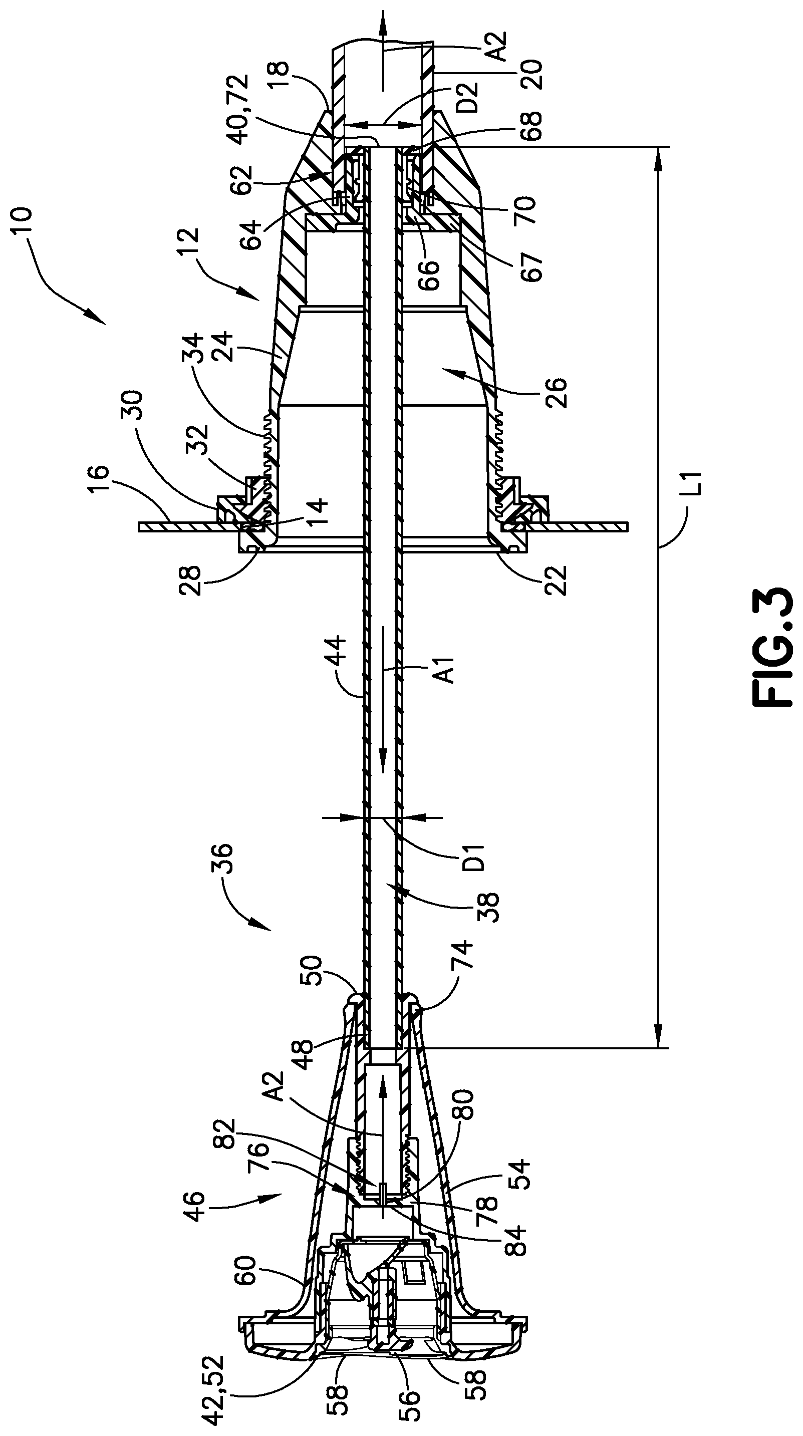
[0044] FIG. 3 is a cross-sectional view of the jet assembly of FIG. 1 in an extended position;
[0045] FIG. 4 is a cross-sectional view of the jet assembly of FIG. 1 in a partially retracted position;
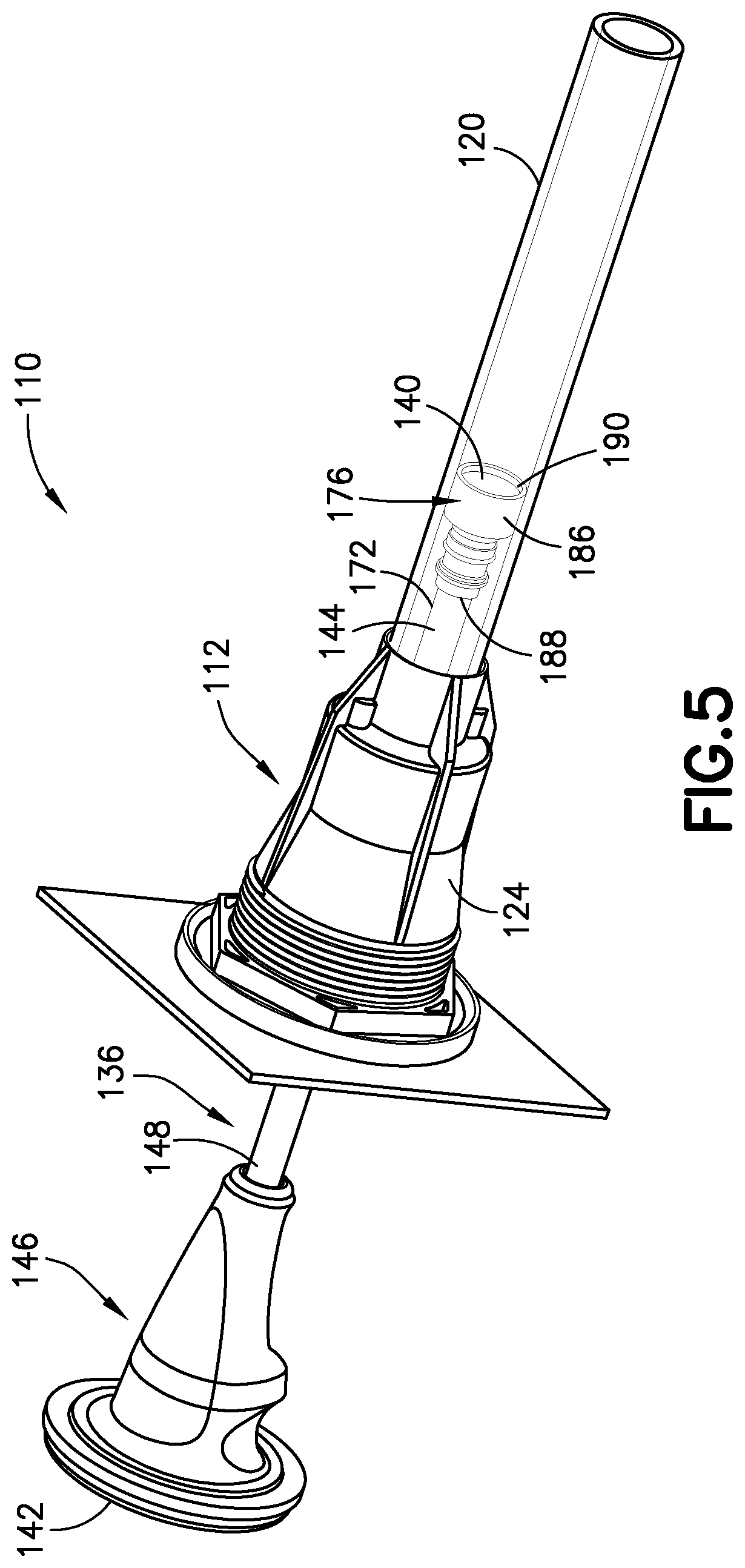
[0046] FIG. 5 is a rearwardly directed perspective view of another example of an extendable jet assembly and fluid line mounted to a sidewall of a spa, according to an aspect of the disclosure;
[0047] FIG. 6 is a frontwardly directed perspective view of the jet assembly of FIG. 5;
[0048] FIG. 7A is a cross-sectional view of the jet assembly of FIG. 5 in an extended position;
[0049] FIG. 7B is a cross-sectional view of the jet assembly of FIG. 5 in a partially retracted position;
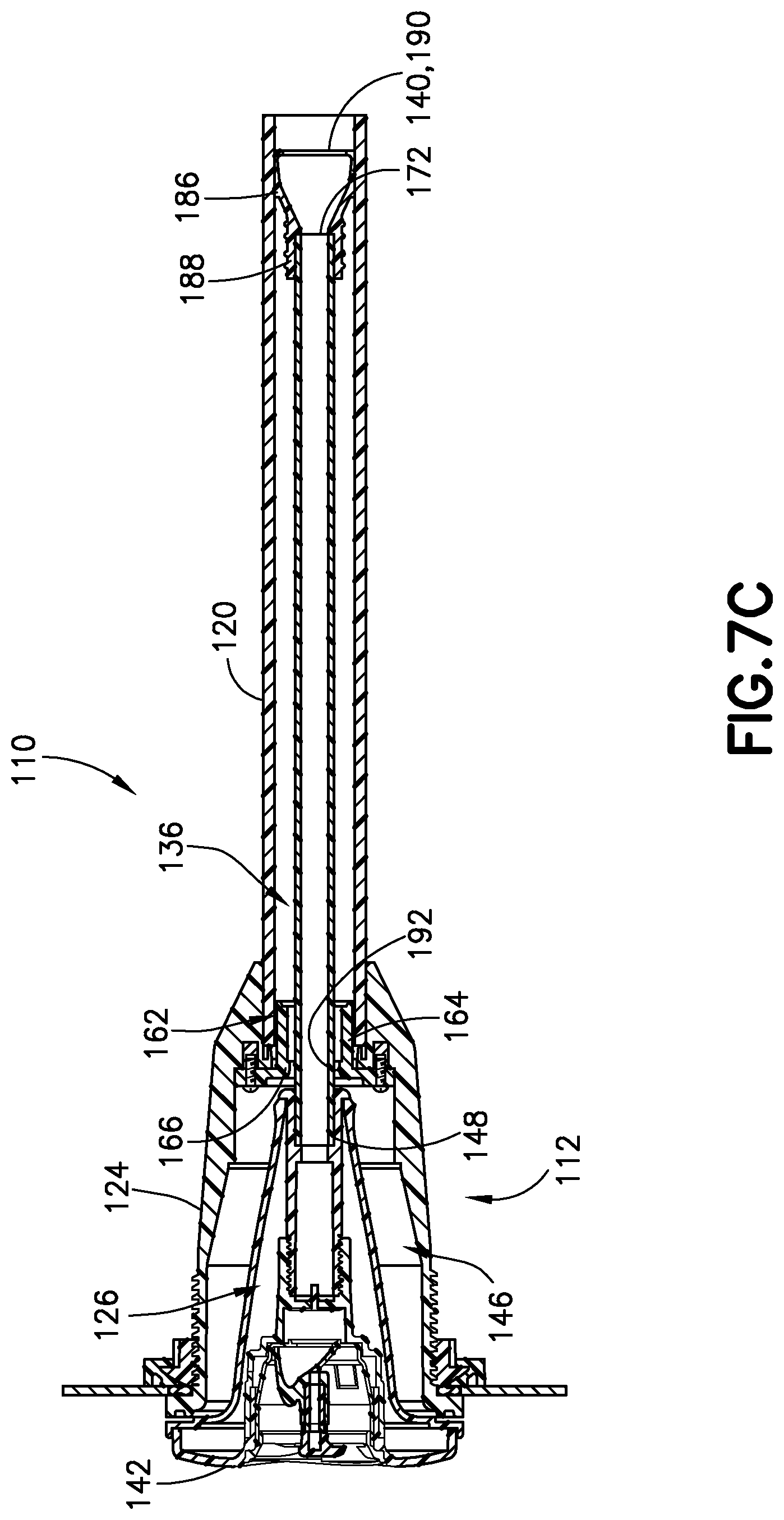
[0050] FIG. 7C is a cross-sectional view of the jet assembly of FIG. 5 in a retracted position;
[0051] FIG. 8 is a perspective view of a fluid circulation system including an extendable jet assembly in an extended position, according to an aspect of the disclosure; and
[0052] FIG. 9 is a schematic drawing of a portion of a spa including the fluid circulation system of FIG. 8, according to an aspect of the disclosure.
DETAILED DESCRIPTION OF THE PRESENT INVENTION
[0053] For purposes of the description hereinafter, the terms "upper", "lower", "right", "left", "vertical", "horizontal", "top", "bottom", "lateral", "longitudinal," and derivatives thereof shall relate to the invention as it is oriented in the drawing figures. The term "proximal" as used herein refers to a portion of an object that is connected to another object or to a portion of the object or element located nearest to an actuating mechanism, such as a pump. For example, a proximal end of the spa jet refers to an end of the jet connected to the spa wall and/or inserted through the spa wall into a space between the spa shell and cabinet. The term "distal" refers to a portion of the object opposite the proximal portion of the object. For example, the "distal" end of a jet or nozzle refers to the portion of the jet or nozzle that extends away from the wall and into the liquid-filled container or vessel. However, it is to be understood that the invention may assume various alternative variations, except where expressly specified to the contrary. It is also to be understood that the specific devices illustrated in the attached drawings, and described in the following specification, are simply exemplary embodiments of the invention. Hence, specific dimensions and other physical characteristics related to the embodiments disclosed herein are not to be considered as limiting.
[0054] The present disclosure is directed to jet assemblies for use with liquid-filled containers, enclosures, reservoirs, vessels, or basins. The contemplated "container" is primarily referred to in this description of the invention as a "spa." As discussed previously, the "container" can also include other water-containing vessels, such as pools, bathtubs, baths, hot tubs, roman tubs, whirlpools, and hydrotherapeutic tubs. The jet assemblies disclosed herein can also be used with other systems and devices for providing a pressurized fluid stream, such as shower heads, steam baths, steamers, facets, sinks, and similar devices. Further, the jet assemblies described herein are generally described as providing a pressurized liquid stream. The jet assemblies disclosed herein may also be configured to provide different fluid streams. For example, the jet assemblies and circulation systems disclosed herein may be adapted to provide a pressurized stream of hot air, steam, water, and combinations thereof.
Jet Assemblies
[0055] With reference to FIGS. 1-4, an extendable jet assembly 10 for a liquid-filled container, enclosure, reservoir, basin, or vessel, such as a spa, tub, bath, and/or shower, includes a housing 12 configured to be positioned in an opening 14 in a wall 16 of the container. The housing 12 includes a proximal end 18 configured to be connected to a liquid conduit 20, such as a tube or pipe. For example, the liquid conduit 20 can be configured to provide a pressurized liquid stream or flow to the jet assembly 10. The housing 12 also includes a distal end 22 extending through the opening 14 of the wall 16 and a sidewall 24 extending between the proximal end 18 and the distal end 22. The housing 12 is a generally hollow structure having an interior space 26 extending between the proximal end 18 and the distal end 22 thereof. The housing 12 can be formed from any sufficiently strong, rigid material configured to withstand temperature and pressure produced by commercially available spas and hot tubs. The housing 12 can be any suitable shape sufficient to fit within the opening 14 of the wall 16 and for connecting to the liquid conduit 20. For example, the housing 12 can be a tapered or conical shape having a wider diameter distal end 22 and a narrower diameter proximal end 18 configured to correspond to a diameter of the liquid conduit 20.
[0056] The jet assembly 10 also includes connectors or fasteners for mounting the housing 12 in the opening 14 of the wall 16 to provide a leak-proof seal between the housing 12 and the wall 16. For example, as shown in FIGS. 3 and 4, the distal end 22 of the housing 12 can include an outwardly flared portion 28 configured to contact an outer surface of the wall 16. The outwardly flared portion 28 can be retained against the wall 16 by, for example, a gasket 30 and a retaining ring 32 positioned on an opposite side of the wall 16 from the flared portion 28 of the housing 12. In some examples, the housing 12 can include a threaded outer surface 34 for installing the gasket 30 and the retaining ring 32 against the wall 16 to hold the jet assembly 10 in place against the wall 16.
[0057] The jet assembly 10 also includes an extendable jet 36 at least partially mounted in the housing 12 and configured to transition from a retracted position (shown in FIG. 2), in which at least a portion of the extendable jet 36 is engaged within the housing 12, to an extended position (shown in FIGS. 1 and 3). The extendable jet 36 defines a liquid channel 38 extending between a proximal end 40 and a distal end 42 thereof for conducting pressurized liquid from the liquid conduit 20 into the container. The extendable jet 36 can include an elongated inflow tube 44 for providing the pressurized liquid from the liquid conduit 20 and/or housing 12 into the extendable jet 36. The inflow tube 44 is generally a narrow tube sized to fit within both the housing 12 and the liquid conduit 20. For example, the inflow tube 44 can have an outer diameter D1, which is less than an inner diameter D2 of the liquid conduit 20 and housing 12. A length L1 of the inflow tube 44 generally determines how far the extendable jet 36 can be extended from the jet housing 12. Accordingly, the length L1 can be selected to permit a user to move the extendable jet 36 away from the wall 16 far enough to direct the stream of pressurized liquid to different areas of the user's body for localized massaging and therapy. The length L1 could also be selected based on the size of the liquid-filled container, such as the spa or tub, the number of other jets in the spa or hot tub, or the arrangement of seats in the spa or hot tub. For example, the length L1 can be from about 48 inches to about 60 inches. In some examples, the inflow tube 44 is formed from a flexible material, such as rubber, or a polymer material, such as polyethylene, vinyl, polyvinyl chloride (e.g., flexible PVC), and/or nylon, to provide greater freedom of movement of the extended jet 36.
[0058] The extendable jet 36 also includes a diffuser 46 connected to a distal end 48 of the inflow tube 44 for expelling the pressurized liquid from the extendable jet 36 and into the container. The diffuser 46 can be a hollow structure having a proximal end 50 connected to the inflow tube 44, a distal end 52 for expelling the liquid stream into the container, and a sidewall 54 extending therebetween. The sidewall 54 of the diffuser 46 is generally shaped to be received within the interior space 26 of the housing 12. For example, the sidewall 54 of the diffuser 46 can be tapered and conical to match a slope of the sidewall 24 of the housing 12. The distal end 52 of the diffuser 46 can include an end plate or cap 56 for imparting different flow characteristics to the liquid stream. For example, the cap 56 can include holes 58 positioned to direct portions of the pressurized liquid stream in different directions. Passing the liquid stream through the holes 58 can, for example, separate the pressurized liquid stream, so that pressurized liquid is provided over a larger target area with reduced force.
[0059] In the retracted position (shown in FIG. 2), the diffuser 46 of the extendable jet 36 engages the housing 12, causing the extendable jet 36 to function as a conventional fixed jet. As the extendable jet 36 transitions from the retracted position to the extended position, the proximal end 50 of the inflow tube 44 passes through a portion of the liquid conduit 20 and into the housing 12 of the jet assembly 10. In the extended position (shown in FIG. 3), the housing 12 engages at least a portion of the inflow tube 44 and at least a portion of the diffuser 46 extends from the housing 12 and into the liquid-filled container. In the extended position, extendable jet 36 can be manipulated in different directions to direct the liquid stream to selected areas of the body. For example, the user can grasp a gripping portion 60 on the outer surface of the sidewall 54 of the diffuser 46. Since the inflow tube 44 is flexible, the user is free to move the diffuser 46 in any direction to adjust directionality of flow from the diffuser 46.
[0060] In some examples, the jet assembly 10 is configured to extend and/or retract due to liquid pressure or suction in the liquid conduit 20. For example, when substantial pressure is present in the liquid conduit 20, the pressure can overcome the engagement between the diffuser 46 and the housing 12, thereby causing the extendable jet 36 to transition from the retracted position to the extended position. Similarly, when a suction force is provided through the liquid conduit 20, the force can cause the inflow tube 44 to disengage from the housing 12, thereby causing the extendable jet 36 to move from the extended position to the retracted position.
[0061] As shown in FIGS. 3 and 4, in some examples, the housing 12 further includes a retainer 62. The retainer 62 can be, for example, an annular sleeve 64 including a flat seat portion 67 positioned in the proximal end 18 of the housing 12. The retainer 62 can be seated against the sidewall 24 of the housing 12, such that an outer surface of the retainer 62 contacts an inner surface of the housing sidewall 24. The retainer 62 can include one or more inwardly directed protrusions 66 for engaging portions of the extendable jet 36 to maintain the extendable jet 36 in the extended or retracted position.
[0062] For example, the retainer 62 can be configured to engage a portion of the diffuser 46 to retain the extendable jet 36 in the retracted position and to engage a portion of the inflow tube 44 to retain at least a proximal end of the extendable jet 36 within the housing 12 when the extendable jet 36 is in the extended position. To facilitate such engagement, the inflow tube 44 of the extendable jet 36 can include a radially extending flange 68 and/or stopper 70 positioned around or adjacent to a proximal end 72 of the inflow tube 44 configured to contact and engage the protrusion(s) 66 of the retainer 62 when the extendable jet 36 is extended. The flange 68 and/or stopper 70 can also be configured to contact and/or seal against an inner surface of the liquid conduit 20 to stabilize the extendable jet 36, as it transitions between positions. The flange 68 and stopper 70 can be formed from any suitable material. The material can be flexible, allowing the flange 68 and/or stopper 70 to deform slightly when moving through the liquid conduit 20 or over the protrusion 66 of the retainer 62. For example, the flange 68 and/or stopper 70 can be formed from an elastomeric material, such as natural rubber, butadiene, polyisoprene, butyl rubber, and/or silicone rubber (e.g., liquid silicone rubber materials).
[0063] In some examples, the diffuser 46 of the extendable jet 36 also includes a locking mechanism or structure configured to be received by and to engage the retainer 62. For example, the diffuser 46 can include a raised protrusion or adapter 74, such as a radially extending flange, collar, ridge, ring, or protrusion, positioned near to the proximal end 50 of the diffuser 46. The adapter 74 can be configured to engage the corresponding protrusion 66 of the retainer 62 when the extendable jet 36 is in the retracted position to retain the extendable jet 36 in place. In some examples, the engagement between the adapter 74 and protrusion 66 is sufficient to maintain the extendable jet 36 in the retracted position when a low level of pressurized liquid is provided through the liquid conduit 20. The adapter 74 can be configured to be released from the retainer 62 when a force of the pressurized liquid flowing through the liquid conduit 20 exceeds a selected level. Alternatively, a user can manually disconnect the jet 36 from the housing 12 by gripping the jet 36 and pulling with sufficient force to overcome the engagement between the adapter 74 and the housing 12.
[0064] In some examples, the extendable jet 36 further includes a valve 76 disposed in the liquid channel 38 of the extendable jet 36 configured to restrict liquid flow through the liquid channel 38. For example, as shown in FIGS. 3 and 4, the valve 76 can be positioned in the diffuser 46 of the extendable jet 36 near the proximal end 50 thereof. The valve 76 can be configured such that, when the valve 76 is open, the extendable jet 36 is configured to transition from the retracted position to the extended position. When the valve 76 is closed, the extendable jet 36 can be configured to transition from the extended position to the retracted position. The valve 76 can be a one-way valve, such as a diaphragm valve, which permits liquid flow through the valve 76 in one direction. The valve 76 closes to prevent liquid from flowing through the valve 76 in the opposite direction.
[0065] In some examples, the valve 76 can be a check valve configured to permit liquid flow through the diffuser 46 and/or inflow tube 44 in one direction (e.g., in a distal direction, as shown by arrow A1) and to prevent fluid flow through the diffuser 46 and/or inflow tube 44 in an opposite direction (e.g., in a proximal direction as shown by arrow A2). The check valve can include an annular body 78 defining a central opening 80 and a movable member, such as a piston 82, extending through the body 78. A seal or seat 84 is connected to the piston 82 and is configured to cover the central opening 80 to seal the opening 80, when the valve 76 is in the closed position. When the valve 76 is open, the piston 82 extends through the central opening 80, thereby separating the seal or seat 84 from the central opening 80 to permit liquid to flow through the valve 76 in the distal direction (shown by arrow A1). For example, the valve 76 can be configured to automatically open when pressurized liquid from the liquid conduit 20 exerts a sufficient force on the piston 82 and/or seat 84. The valve 76 can be configured to automatically close when a suction force in the liquid conduit 20 is applied to the piston 82 and/or seat 84. The valve 76 may also close in response to fluid pressure exerted on the piston 82 and/or seat 84 from liquid in the liquid-filled container, which can push the seat 84 to the closed position.
[0066] The jet assembly 10 can operate in the following manner. The jet assembly 10 can be initially provided in a retracted position (shown in FIG. 2). When a pressurized liquid stream of sufficient force is present in the liquid conduit 20, the valve 76 moves to an open position. In addition to causing the valve 76 to open, the pressurized liquid exerts a force against the extendable jet 36 sufficient to overcome the engagement between the extendable jet 36 and housing 12. Once the engagement between the housing 12 and jet 36 is overcome, the jet 36 moves from the retracted position to an extended position (shown in FIGS. 1 and 3). The jet assembly 10 is shown between the retracted position and the extended position in FIG. 4. In the extended position, a user can grip the outer surface of the diffuser 46 and move the diffuser 46 to direct pressurized liquid towards different selected areas of the user's body. In the extended position, as discussed previously, the valve 76 is open and the inflow tube 44 is engaged to the retainer 62 of the housing 12 to maintain the extendable jet 36 in the extended position. The engagement between the inflow tube 44 and retainer 62 also prevents the user from pulling the extendable jet 36 entirely out of the housing 12.
[0067] Another example of an extendable jet assembly 110 is shown in FIGS. 5-7C. As in previous examples, the jet assembly 110 includes the housing 112 and the extendable jet 136 positioned within and/or mounted to the housing 112. The jet 136 includes an elongated inflow tube 144 and a diffuser 146 connected to a distal end 148 of the inflow tube 144 for expelling pressurized liquid from the jet 136 and into a liquid-filled container. The jet 136 is configured to transition from a retracted position (shown in FIGS. 6 and 7C), in which at least a portion of the diffuser 146 is engaged within the housing 112, to an extended position (shown in FIGS. 5 and 7A), in which the housing 112 engages at least a portion of the inflow tube 144 and at least a portion of the diffuser 146 extends from the housing 112 and into the liquid-filled container.
[0068] Also, as in previous examples, the jet assembly 110 includes a valve 176. The valve 176 can be a check valve configured to automatically open when pressurized liquid is present in the liquid conduit 120 to permit fluid flow from the liquid conduit 120 through the jet 136 and into the liquid-filled container. The valve 176 can be configured to automatically close when a suction force or negative pressure is present in the liquid conduit 120 to prevent liquid from flowing through the valve 176 in the opposite direction. As shown in FIGS. 7A-7C, unlike in previous examples, the valve 176 is connected to a proximal end 172 of the inflow tube 144 rather than within the diffuser 146. The check valve 176 includes a body or housing 186 having a distal end 188 connected to the inflow tube 144 and a free or open proximal end 190. A movable valve member, such as a piston (not shown), is positioned inside the body or housing 186 of the valve 176 and configured to move from a closed position, in which liquid flow through the valve 176 is restricted, to an open position, in which liquid flow through the valve 176 and the jet 136 from a proximal end 140 to a distal end 142 thereof is permitted. As shown in FIG. 7A, the body or housing 186 of the valve 176 is sized to be received by and to engage a retainer 162 positioned in an interior space 126 of the housing 112. As discussed above, the retainer 162 can be an annular sleeve 164 positioned such that an outer surface of the sleeve contacts an inner surface of a sidewall 124 of the housing 112. The annular sleeve 164 can include one or more radially inwardly directed protrusions 166 extending from an inner surface of the sleeve 164, which engage the valve housing 186 to maintain the valve 176 and jet 136 in the extended position (shown in FIG. 7A).
[0069] In some examples, the retainer 162 can further include a wiper seal 192 extending radially inwardly from an inner surface of the sleeve 164. As shown in FIGS. 7A-7C, the wiper seal 192 can be sized to seal an outer surface of the inflow tube 144 to restrict liquid flow from the liquid-filled container into the liquid conduit 120. In order to provide a sufficient seal, the wiper seal 192 can be formed from a flexible and resilient material, such as an elastomeric material, which deforms slightly when the inflow tube 144 passes through the wiper seal 192, thereby providing a suitable seal between the wiper seal 192 and the inflow tube 144. The wiper seal 192 is desirably sufficiently deformable so that the inflow tube 144 can pass through the wiper seal 192 in either direction. The wiper seal 192 can be configured to provide self-cleaning for the jet 136 by removing any objects attached to the inflow tube 144 as the inflow tube 144 extends and retracts through the wiper seal 192.
[0070] The jet assembly 110 shown in FIGS. 5-7C functions in a similar manner to previously described examples. For example, the jet assembly 110 can be initially provided in a retracted position, as shown in FIG. 7C. When a pressurized liquid stream is present in the liquid conduit 120, the valve 176 moves to an open position and, as pressure increases, exerts a force against the jet 136 sufficient to overcome the engagement between the jet 136 and the housing 112. Once the engagement between the jet 136 and the housing 112 is overcome, the jet 136 moves from the retracted position (shown in FIG. 7C) to the extended position (shown in FIG. 7A). The jet assembly 110 is shown between the retracted position and the extended position in FIG. 7B. As discussed previously, in the extended position, a user can grip the outer surface of the diffuser 146 and can move the diffuser 146 to direct pressurized liquid towards different selected areas of the user's body. In the extended position, as discussed previously, the valve 176 is open and the inflow tube 144 is engaged to the retainer 162 of the housing 112 to maintain the jet 136 in the extended position.
Liquid Circulation System
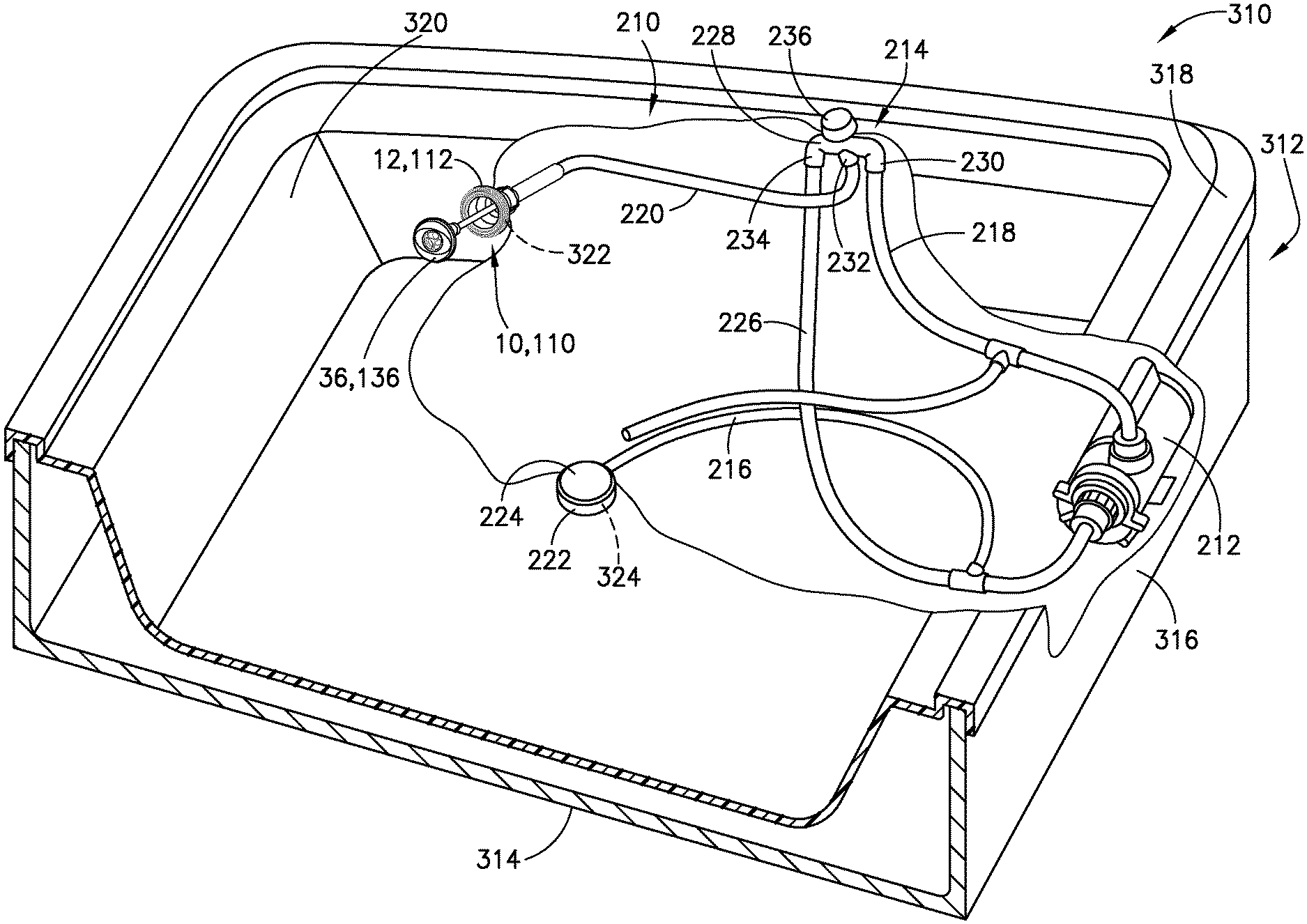
[0071] As shown in FIGS. 8 and 9, the extendable jet(s) 36, 136 described herein can be used with a liquid circulation system 210, such as a liquid circulation system for a liquid-filled container, such as a spa, hot tub, or bathtub. For example, FIG. 9 shows the liquid circulation system 210 installed in a spa 310. The liquid circulation system 210 can be an existing liquid circulation system for a spa retrofit to include the extendable jet(s) 36, 136 as described herein. In other examples, a spa and liquid circulation system can be specifically designed to include one or more of the exemplary extendable jet assemblies 10, 110 described herein.
[0072] In some examples, the liquid circulation system 210 includes a liquid circulation pump 212 configured to provide a stream of pressurized liquid to one or more jet assemblies 10, at least one diverter valve 214 for controlling liquid flow to the one or more jet assemblies 10, and one or more conduits 216, 218, 220, 226 for connecting the liquid-filled container (e.g., the spa shell 320), pump 212, diverter valve(s) 214, and jet assembly(s) 10, 110.
[0073] The system 210 can further include at least one suction port or outlet 222 extending through a wall of the liquid-filled container for drawing liquid from the container to the pump 212. For example, the suction outlet 222 can be a hollow opening connected to the pump through the conduits 216, 218, 220, 226. In some examples, the suction outlet 222 can also include an end plate 224 or cover plate for filtering solid objects from the liquid being drawn into the liquid circulation system 210 through the outlet 222. The system 210 can further include at least one conventional fixed valve (not shown) extending through the wall of the liquid-filled container and in fluid communication with the circulation pump 210 for providing additional streams of fluid into the spa shell 320.
[0074] The one or more conduits 216, 218, 220, 226 can include, for example, an aspiration or return conduit 216 adapted to conduct liquid from the container (e.g., from the spa shell 320) to the pump 212. The one or more conduits 216, 218, 220, 226 can also include a supply conduit 218 in fluid communication with and positioned downstream of the circulation pump 212 for delivering pressurized liquid from the circulation pump 210 to the diverter valve 214. The one or more conduits 216, 218, 220, 226 can also include a jet assembly conduit 220 (referred to previously as the liquid conduit 20, 120) extending between the jet assembly 10, 110 and the diverter valve 214, which provides either pressurized liquid from the supply conduit 218 to the jet assembly 10, 110 or a suction force from the return conduit 216 to the jet assembly 10, 110. The one or more conduits 216, 218, 220, 226 can further include a discharge conduit 226 connected between the diverter valve 214 and the return conduit 216. The discharge conduit 226 is configured to divert a portion of the pressurized liquid directed from the pump 212 towards the diverter valve 214 and jet assembly 10, 110 back to the circulation pump 212. Accordingly, the discharge conduit 226 functions to bypass pressurized liquid from the circulation pump 212 when the diverter valve 214 is actuated in a less than fully open position, which is useful for providing a lower flow rate of pressurized liquid through the jet assembly 10, 110.
[0075] In some examples, the diverter valve 214 is a three-way valve adapted to change a rate of flow of liquid supplied to the jet assembly 10, 110. Adjusting the flow rate or force of the pressurized liquid can also control extension and retraction of the jet 36, 136 of the jet assembly 10, 110. The diverter valve 214 can be any suitable three-way, manually operated diverter valve which diverts water between the jet assembly 10, 110 and the discharge conduit 226 to control liquid flow through the jet assembly 10, 110. In some examples, the diverter valve 214 can include a hollow valve body 228 with an inlet port 230, a first outlet port 232, and a second outlet port 234. The inlet port 230 is in fluid communication with the circulation pump 212 through the supply conduit 218, the first outlet port 232 is in fluid communication with the jet assembly 10, 110 through the jet conduit 220, and the second outlet port 234 is in fluid communication with the discharge conduit 226. The diverter valve 214 further includes a plunger (not shown) disposed within the valve body 228. The plunger is operatively coupled to a plunger actuation mechanism, which is, in turn, coupled to a rotating actuator knob 236. The actuator knob 236 may be positioned at any convenient location on the liquid-filled container, such as on an upper edge of the container or at any other convenient location, thereby allowing a user to adjust the rate of flow of water supplied to the jet assembly 10, 110. The plunger may further include a seal, such as an o-ring (not shown), adapted to provide a fluid-tight seal between the plunger and the second outlet port 234 and/or a fluid-tight seal between the plunger and the first outlet port 232.
[0076] The actuator knob 236 may be adjustable to an infinite number of positions or may have a predetermined number of positions. For example, the knob 236 may have three positions. The knob 236 can be moved between the three positions by rotating the knob 236 in a clockwise or counterclockwise direction. When the actuator knob 236 is in a first or clockwise position, the plunger actuation mechanism forces the plunger into a first position where a fluid-tight seal is created between the o-ring of the plunger and the first outlet port 232. In this configuration, none of the liquid passing through the liquid circulation pump 212 passes through the first outlet port 232 to the jet conduit 220 and jet assembly 10, 110. Instead, all of the pressurized liquid from the liquid circulation pump 212 passes through the second outlet port 234 to the discharge conduit 226. When the actuator knob 236 is in this first or clockwise position, the jet assembly 10, 110 remains in the retracted position since no fluid pressure is present in the liquid conduit 220 to force the jet 36, 136 to the extended position. Also, the valve 76 (shown in FIGS. 3 and 4) of the extendable jet 36 or valve 176 (shown in FIGS. 7A-7C) of the extendable jet 136 is closed. While a user may manually extend the extendable jet 36, 136 by, for example, gripping the jet 36, 136 and pulling it away from the housing 12, 112 this action is not recommended, since no pressurized fluid comes out of the jet 36, 136 when the knob 236 is in the first or clockwise position. However, the jet 36, 136 can be configured such that manually pulling or forcing out the jet 36, 136, while not recommended, does not damage the system 210.
[0077] When a user adjusts the actuator knob 236 of the diverter valve 214 from the first or clockwise position to a second or counterclockwise position, the plunger seals the second outlet port 234, thereby forcing all of the liquid passing through the liquid circulation pump 212 and supply conduit 218 to pass through the first outlet port 232 to the jet conduit 220 and jet assembly 10, 110. For example, adjusting the knob 236 could require the user to rotate the knob 236 by 180 degrees in the counterclockwise direction, which moves the knob 236 from the first or clockwise position to the second or counterclockwise position. In this second or counterclockwise position, the pressurized liquid exerts substantial force on the jet assembly 10, 110. In particular, the force is exerted against the valve 76, 176 of the extendable jet 36, 136 causing the extendable jet 36, 136 to open to permit fluid flow through the extendable jet 36, 136. Force of the pressurized liquid may also be exerted on proximal portions of the extendable jet 36, 136, such as the flange 68 and/or the stopper 70 (shown in FIGS. 3 and 4). The substantial force can be sufficient to overcome the engagement between the extendable jet 36, 136 and jet assembly housing 12, 112, thereby causing the extendable jet 36, 136 to extend from the housing 12, 112 (e.g., to transition from the retracted position to the extended position).
[0078] The knob 236 and valve 214 can be configured such that the jet 36, 136 only retracts or extends when the knob 236 is in one of two positions, namely the first or clockwise position or the second or counterclockwise position. When a user positions actuator knob 236 in a third position (e.g., for a knob 236 with three separate positions) or in any of the infinite number of positions between the first position and the second position (e.g., for a rotatable knob assembly), the plunger actuation mechanism forces the plunger into a position where neither the first outlet port 232 nor the second outlet port 234 is sealed. In this configuration, a portion of the liquid provided from the pump 212 through the supply conduit 218 passes through the first outlet port 232 to the jet conduit 220 and through the jet assembly 10, 110 and a portion of the liquid passes through the second outlet port 234 to the discharge conduit 226. When in this third or middle position, the jet assembly 10, 110 can be configured to remain in a current position and neither to extend nor retract therefrom. For example, if the jet assembly 10, 110 is in the retracted position, then moving the actuator knob 236 to the third or middle position causes the jet assembly 10, 110 to act as a conventional fixed jet, in which the extendable jet 36, 136 remains engaged within the housing 12, 112 of the jet assembly 10. For example, the portion of liquid passing to the jet assembly 10, 110 can open the valve 76, 176 of the extendable jet 36, 136 so that the pressurized liquid is expelled from the extendable jet 36, 136 into the container (e.g., into the spa shell 320). However, the liquid pressure does not overcome the engagement between the extendable jet 36, 136 and jet assembly housing 12, 112, meaning that the jet assembly 10, 110 remains in the retracted position. When the extendable jet 36, 136 is in the extended position, moving the actuator knob 236 from the second position to the third position reduces an intensity or force of liquid expelled from the extendable jet 36, 136 compared to when the actuator knob 236 is in the second position. However, moving the actuator knob 236 to the third position does not cause the extendable jet 36, 136 to retract into the housing 12, 112.
[0079] In some examples, moving the actuator knob 236 from the second position or from the third position to the first position causes the extendable jet 36, 136 to retract into the jet housing 12, 112. For example, moving the actuator knob 236 from the second position to the first position begins to close the first outlet port 232 and to open the second outlet port 234. As the second outlet port 234 opens, an increasing portion of the pressurized liquid passing through the diverter valve 214 is diverted to the discharge conduit 226 and a reduced portion of the pressurized fluid passes through the first outlet port 232 into the jet conduit 220. As a result of the reduction in pressurized fluid provided to the jet conduit 220, a liquid pressure in the jet conduit 220 decreases causing the valve 76, 176 of the extendable jet 36, 136 to close. Eventually, due to opening of the second outlet port 234, the pressure in the diverter valve 214 and discharge conduit 216 exceeds the pressure in the jet conduit 220. It is believed that this pressure difference between the jet conduit 220 and diverter valve 214 causes fluid in the jet conduit 220 to be drawn back through the jet conduit 220 towards the diverter valve 214 and discharge conduit 216, thereby creating a Venturi effect or suction force. This created suction force can also be sufficient to cause the extendable jet 36, 136 to retract into the housing 12, 112. Alternatively, a user may manually retract the extendable jet 36, 136 into the housing 12, 112 by pushing the extendable jet 36, 136 into the housing 12, 112 with sufficient force to disengage the portion of the inflow tube 44 (shown in FIGS. 1-4) or inflow tube 144 (shown in FIGS. 5-7C) from the housing 12, 112.
[0080] Once in the fully retracted position, the extendable jet 36, 136 engages the jet assembly housing 12, 112, thereby retaining the extendable jet 36, 136 in the retracted position. Once the extendable jet 36, 136 is engaged in the retracted position, the user can move the actuator knob 236 to the third position, thereby causing the jet assembly 10, 110 to function as a fixed jet. However, this example is not to be construed as limiting the present invention, as an actuator knob with any suitable number of positions has been envisioned.
[0081] In some examples, the liquid circulation system 210 further includes a high-flow heater and a flow switch positioned upstream from diverter valve and downstream from the circulation pump. In some examples, the heater and/or flow switch could also be enclosed in a housing of the pump 212. The high-flow heater heats the pressurized liquid from the circulation pump 212, thereby allowing heated water to be provided to the jet assembly(s) 10, 110. The flow switch can be provided to sense water flow and provide an electrical interlock which shuts down the heater upon loss of flow through the circulation system 210. An ozone injector (not shown) can also be provided in fluid communication with the flow switch and the liquid circulation system 210. The ozone injector supplies ozone to the liquid for disinfection and cleaning purposes.
[0082] FIG. 9 shows the fluid circulation system 210 installed in the spa 310. The spa 310 can be a conventional spa or hot tub, as is known in the art, including, for example, a cabinet 312 having a bottom 314, upwardly projecting sides 316, and an open top 318. The spa 310 also includes a container, such as the shell 320, configured to contain the liquid. As discussed previously, the fluid circulation systems 210 disclosed herein can also be used with other water-containing vessels, such as pools, bathtubs, baths, hot tubs, roman tubs, whirlpools, and hydrotherapeutic tubs.
[0083] As shown in FIG. 9, the liquid circulation system 210 includes conduits 216, 218, 220, 226 for circulating liquid between the liquid-filled shell 320 and elements of the system 210, such as the pump 212. The conduits 216, 218, 220, 226 and other elements of the liquid circulation system 210 are disposed in spaces between the cabinet 212 and the shell 320. Electromechanical devices, such as the pump 212 and/or heater, can also be disposed between the shell 320 and the cabinet 312. The shell 320 includes a circular opening 322 sized to receive the housing 12, 112 of the jet assembly 10, 110. The shell 320 also includes an opening 324 for the suction outlet 222, for drawing liquid from the shell 320 into the circulation system 210. The cabinet 312 and shell 320 can be any common size, as is known in the art. For example, a conventional spa 310 can be about 6 ft wide, 6 ft long, and about 4 ft high. However, spas of any size can be adapted to include the liquid circulation system 210 and extendable jet(s) 36, 136, described herein.
[0084] Although the invention has been described in detail for the purpose of illustration based on what is currently considered to be the most practical and preferred embodiments, it is to be understood that such detail is solely for that purpose and that the invention is not limited to the disclosed embodiments, but, on the contrary, is intended to cover modifications and equivalent arrangements. Furthermore, it is to be understood that the present invention contemplates that, to the extent possible, one or more features of any embodiment can be combined with one or more features of any other embodiment.
* * * * *
D00000
D00001
D00002
D00003
D00004
D00005
D00006
D00007
D00008
D00009
D00010
D00011
XML
uspto.report is an independent third-party trademark research tool that is not affiliated, endorsed, or sponsored by the United States Patent and Trademark Office (USPTO) or any other governmental organization. The information provided by uspto.report is based on publicly available data at the time of writing and is intended for informational purposes only.
While we strive to provide accurate and up-to-date information, we do not guarantee the accuracy, completeness, reliability, or suitability of the information displayed on this site. The use of this site is at your own risk. Any reliance you place on such information is therefore strictly at your own risk.
All official trademark data, including owner information, should be verified by visiting the official USPTO website at www.uspto.gov. This site is not intended to replace professional legal advice and should not be used as a substitute for consulting with a legal professional who is knowledgeable about trademark law.